Mais conteúdo relacionado Semelhante a Automatic Structural Optimization of Engine Components Using HCF and TMF Failure Analysis and Optimization Models (20) 1. AMAE Int. J. on Production and Industrial Engineering, Vol. 01, No. 01, Dec 2010
© 2010 AMAE
DOI: 01.IJPIE.01.01.13
14
Automatic Structural Optimization of Engine
Components Using HCF and TMF Failure Analysis
and Optimization Models
Dr. J. David Rathnaraj1
, G. Jims John Wessley2
, & Rajakumar S Rai3
1
Sri Ramakrishna Engineering College, Manufacturing Engineering, Coimbatore, India
Email : jebamani@rediffmail.com
2,3
Karunya University, School of Mechanical Sciences, Coimbatore, India
Email:jims_john@yahoo.com
Abstract- Modern combustion methods and the constant wish
for an increase in the specific performance results in high
thermal and mechanical loads in modern combustion engines.
In order to shorten the development time, an interactive,
simultaneous execution of design (CAD) and calculation
activities (CAE) is necessary. In this the product must be looked
at in detail and be optimized in various disciplines and in a
harmonized way of procedure to the development progress. In
the initial proactive phase the efficiency of virtual CAE-
methods is high and quickly decreases in the second half of the
development, which shows strongly reactive features. Therefore
a combined HCF (High-Cycle-Fatigue) Failure Analysis and
Optimization and TMF (Thermo-Mechanical-Fatigue) Failure
Analysis and Optimization model is discussed in this paper for
the reduction in the analysis time.
Index Terms- Exhaust manifold, HCF, TMF, FEM, FEV
I. INTRODUCTION
Exhaust Manifold is a simple pipe, which carries the
burned gases. In a multi cylinder engine, individual pipes
collect the combustion products from various cylinders and
lead to a single outlet pipe. Exhaust manifold is subjected to
thermal boundary conditions (loading).
A. Basic functions of the exhaust manifold
1. It is a pipe which carries awaythe burned gases out
of the engine cylinders
2. It insulates the exhaust gases from the surrounding
so that catalytic converter functions well; the functioning
of the catalytic converter depends on the prevailing
temperature in the manifold.
3. It conducts away sufficient amount of heat so that
inner surface temperature of the exhaust manifold is
less than the melting point of the exhaust manifold.
1
Corresponding Author
II. SHAPE OPTIMIZATION
Shape optimization can be differentiated in parametric
and parameter-free methods. In a parametric optimization
design parameters such as length and radii are modified. In
the ideal case this already takes place in the CAD system
with automatic secondary FEM (Finite Element Method)
calculation; in practice this method is often impeded by
interface problems.Apart from that, the space for the possible
solution is considerably restricted, owing tothe limited num-
ber of design variables. Due to which the solution found, in
comparison to the possible solution in the complete solution
space shows only sub-optimal properties. In highly stressed
components like the curvature resistant surfaces this has
turned out to be of advantage as regards to stress distribu-
tion. Hence a simple parameterization with radii of curva-
ture resistance can only be achieved with difficulty.
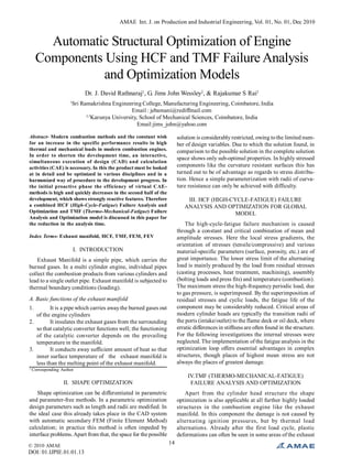
III. HCF (HIGH-CYCLE-FATIGUE) FAILURE
ANALYSIS AND OPTIMIZATION FOR GLOBAL
MODEL
The high-cycle-fatigue failure mechanism is caused
through a constant and critical combination of mean and
amplitude stresses. Here the local stress gradients, the
orientation of stresses (tensile/compressive) and various
material-specific parameters (surface, porosity, etc.) are of
great importance. The lower stress limit of the alternating
load is mainly produced by the load from residual stresses
(casting processes, heat treatment, machining), assembly
(bolting loads and press fits) and temperature (combustion).
The maximum stress the high-frequency periodic load, due
to gas pressure, is superimposed. By the superimposition of
residual stresses and cyclic loads, the fatigue life of the
component may be considerably reduced. Critical areas of
modern cylinder heads are typically the transition radii of
the ports (intake/outlet) to the flame deck or oil deck, where
erratic differences in stiffness are often found in the structure.
For the following investigations the internal stresses were
neglected. The implementation of the fatigue analysis in the
optimization loop offers essential advantages in complex
structures, though places of highest mean stress are not
always the places of greatest damage.
IV.TMF (THERMO-MECHANICAL-FATIGUE)
FAILURE ANALYSIS AND OPTIMIZATION
Apart from the cylinder head structure the shape
optimization is also applicable at all further highly loaded
structures in the combustion engine like the exhaust
manifold. In this component the damage is not caused by
alternating ignition pressures, but by thermal load
alternations. Already after the first load cycle, plastic
deformations can often be seen in some areas of the exhaust
2. AMAE Int. J. on Production and Industrial Engineering, Vol. 01, No. 01, Dec 2010
© 2010 AMAE
DOI: 01.IJPIE.01.01.13
15
manifold. The high material temperatures due to the limited
possibility of thermal expansion, owing to different mate-
rial parameters and the screwed connection, lead to high
compressive stresses, which locally exceed the yield point
of the hot solid material.
Figure 1. HCF (High-Cycle-Fatigue) Failure Analysis and Optimization
for Global Model
In these plasticized zones the compressive stresses, after
cooling down of the engine, change into local tensile stresses,
which in the unfavorable case can locally exceed the tensile
yield point. In such a case cyclically repeated plastic strain
amplitude occurs, which is the basis for the thermo-mechani-
cal failure mechanism. Special importance in this connec-
tion is also given to the contact formulations between cylin-
der head, gasket and exhaust manifold, as well as the non-
linear behavior of the exhaust manifold gasket. Compared
to the fatigue life characteristics from experiments, the ser-
vice life of the component can be determined via strain or
energyapproaches. As the optimality criteria is also applied
to moderately non-linear analyses like plasticity or hyper-
elasticity, also certain non-linear analyses can be used in
shape optimization. As regards to the plasticity, a homog-
enization of the elastic and plastic stain energy is strived for,
bywhich the maximum strain energy and with that the maxi-
mum plastic strain is reduced. Therefore, the optimization
quantity, in the first formulation, is not a damage that is
looked at, but plastic strain amplitude. From the results of
the test bench runs, a good correlation of crack starting points
to areas of high plastic strain amplitude can be derived in
comparison to the analyses. An extension of the TMF-based
damage calculation and integration into the optimization
process is in principle possible. The determination of the
damage through TMF is comparable tothe alreadydescribed
analyses at the cylinder head. In the thermal analysis the
influence of radiation is taken into consideration, besides
comparable boundary conditions as used for the cylinder
head analysis. Averaged heat transfer coefficients and gas
temperatures are determined as in stationary CFD analyses.
A. The mechanical loads consist of the following:
• Pre-stresses from bolt loads
• Thermo-mechanical stresses caused by various
thermal expnsion coefficients of cylinder head and ex-
haust manifold as well as other mounting parts.
• Thermo-mechanic stresses through temperature gradients
in the materials of the component parts
Residual stresses and dynamic stresses can be neglected for
the determination of the TMF-failure. The optimization of
the exhaust manifold and the analysis takes place according
to the “closed loop” method, (i.e.) by integration of the ther-
mal analysis. The gas-side boundary conditions are kept
constant, as in the first approximation the local modifica-
tions at the geometry do not have any significant effects on
the gas flow. As an exact representation of the temperature
distribution for the evaluation of TMF is important, mea-
surement based on thermo-scan methods or by means of
thermo-color can be carried out in the preliminary stages of
the analyses.
All internal and external surfaces of the ports were selected
as design area. The geometry of the flange surfaces and bolt
bores were fixed. During the mechanical analysis the fol-
lowing load history is passed through:
1. Assembly
2. Thermal load
3. Cooling down to room temperature
4. Thermal load
5. Cooling down to room temperature
The total analysis time is at approx. 2.5 hours, with the ther-
mal and mechanical analysis representing almost 100 % of
the work. In total 30 optimization loops were carried out.
The release of such a large design area is a challenge for the
optimization algorithm. Local modifications at one area can
change the total stiffness of the exhaust manifold and con-
sequently influence the results of further areas.
Figure 2. Temperature distribution measurement based on thermo-scan
method
This is very well recognized in the internal area of the
flange to the turbocharger. Here after 9 cycles a plastic strain
reduced by 53 % is achieved. After 13 cycles, the local result
aggravates to –35 % and the optimal result is achieved after
15 cycles.
V. CONCLUSION
The possibilityof carrying out a shape optimization
on an already existing FE-model, by taking non-linear
behavior and specific service life simulation into
consideration, has turned to be an enormous relief and
noticeable improvement in the development process.
3. AMAE Int. J. on Production and Industrial Engineering, Vol. 01, No. 01, Dec 2010
© 2010 AMAE
DOI: 01.IJPIE.01.01.13
16
Figure 3. Thermal and Mechanical analysis
The geometry modifications achieved are partly
very minor, but have a very strong influence on the service
life and on the quality of the component parts.
Material saving at equal service life and by using
the same materials, a significant extension in the fatigue life
is achieved.
The complex task of the optimization of a large area
with plastic strain amplitudes has given a very good result
with a reduction in the critical values of 50 % and more.
The first steps for the implementation of the FEV
Software into the optimization cycle for TMF driven
problems is achieved.
VI. REFERENCES
[1] Deger.Y., “Simulation of Thermo mechanical Load Cases”,
Sulzer Technical Review, Vol.3, 2003.
[2] Simperl.B., Schöck.J. Deger.Y, “Thermal Deformation and
Stresses in an Exhaust Manifold”, Technical Report Nr. TB03_0123,
Sulzer Innotec, Oct. 2003, (not public).
[3] ABAQUS User’s Manual, Version 6.7
[4] S.S. Manson;”Behaviour of materials under conditions of
thermal stresses”, Technical report, TN 2933, N.A.C.A, 1953
[5] N. Mamiya; et al. “Thermal fatigue life of exhaust manifolds
predicted by simulation”, SAE Paper no. 01-0854, 2002
[6] P.O. Santacreu; et al. “Study of thermal fatigue of stainless
steels and its application to the life prediction of automotive exhaust
line components”, Congress Thermal Stress’99, Cracow, Poland,
Skrzypek and R.B.HetnarskiEds., pp.245,1999.
[7] Sandeep Patel, Nickel Daniel, “Structural Optimization of
Engine Components Using ABAQUS and TOSCA”, Project
report,2007