Basic Civil Engineering first year Notes- Chapter 4 Building.pptx
MET 304 Belt drives
1. Mechanical Design Belt
drives
Belt drives
5.1 Introduction
Belts are used to transmit motion between shafts that are located at a
considerable distance from each other. They are not used for exact fixed
speed ratio because slipping may occur during motion. They are very
flexible when considering the distance or the angle between the two shafts.
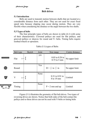
5.3 Types of belts
The four principle types of belts are shown in table (6.1) with some
of their characteristics. Crowned pulleys are used for flat pulleys, and
grooved pulleys or sheaves for round and V- belts. Timing belts require
toothed wheels or sprockets.
Table (5.1) types of Belts
Belt type Sketch Joint Size range Centre distance
yes
Flat t= { 0.03 to 0.20 in
0.75 to 5 mm
No upper limit
Yes
1 3
Round D= 8 to 4 in No upper limit
None
0.31 to 0.91 in
V t= { 8 to 19 mm
Limited
None
P Timing P = 2 mm and up Limited
Figure (5.1) illustrates the geometry of flat belt drives. Two types of
reversing drives are shown. Notice that both sides of the belt contact the
pulleys and so these drives can not be used with V-belts or timing belts
Dr. Salah Gasim Ahmed YIC 1
2. Mechanical Design Belt
drives
Non-reversing Open Belt
Reversing Crossed Belt
Reversing Open Belt
Quarter Twist Belt drive
Fig. (5.1)Layout of Flat belt drive
Dr. Salah Gasim Ahmed YIC 2
3. Mechanical Design Belt
drives
V-Belts
V-belts are used widely in machine tools. They can be obtained with
different lengths and sizes. There are five standard sizes of V-belts: A, B, C,
D, E as shown in fig. (5.2).
1
1
1 2
1
7 4
1 21 8
32
2
3 29
5 13 17 32
4
16 32 32
A B C D E
Fig. (5.2) Cross-sections of V-belts
5.2 Selection of V-belts:
The following information should be available for the selection of a
suitable V-belt:
1. Power to be transmitted
2. Speed of the small or large pulley
3. Speed ratio
4. Field of application.
5. Approximate distance between the centres of the two pulleys
The following steps can used to select a suitable V-belt based on the
information mentioned above:
1. Determine the service factor depending on the field of application,
from table (5.2).Obtain the design power from the equation:
Design power = transmitted power x service factor
(5.1)
2. Select a suitable belt size from fig.(5.3) at the intersection of the
speed of the small pulley and the design power.
3. Find the diameter of the small pulley (d) from table (5.3).
4. Find the diameter of the large pulley (D) from the equation:
D= d x speed ratio (5.2)
5. Find the length of the belt using the equation:
( D − d )2
L = 2C + 1.57( D + d ) + (5.3)
4C
Where:
L: length of belt
Dr. Salah Gasim Ahmed YIC 3
4. Mechanical Design Belt
drives
C: Centre distance between shafts
5000
Consult
Speed of 3000 Manufacturers
small pulley2000
(rpm) A B
1000
800
500 C
300 D
200 E
100
1 2 3 5 7 10 20 30 50 100 200 300 500
Design horse power
Fig. (5.3) Selection of V-belts
6. Obtain the standard length of the belt from table (5.4)
7. Calculate the exact centre distance from the equation:
b + b 2 − 32( D − d ) 2
C= (5.4)
16
Where,
b = 4 L − 6.28( D + d ) (5.5)
8. Find the angle of lap (arc of contact), from the equation:
( D − d )60
Angle of lap = 180 − C
(5.6)
9. Find the capacity of one belt from the equation:
YxS
XS 0.91 − − ZS 3
Capacity of one belt = de (5.7)
The values of X,Y and Z can obtained from table (5.5)
The equivalent small pulley diameter de can be obtained from the
equation:
de = diameter of small pulley x coefficient of small pulley (5.8)
The coefficient of the small pulley is obtained from table (5.6)
The linear speed of the belt, S, in thousands of feet can be obtained
from the equation:
S = (3.142xP.D x RPM)/12000 (5.9)
Where P.D. is the pitch diameter of the small pulley
10. Find the power transmitted by one belt from the equation:
11. Power of one belt =belt capacity x length coefficient x coefficient of arc of contact (5.10)
The coefficient of arc of contact can be obtained from table (5.7) and
the length coefficient can be obtained from table (5.8)
Dr. Salah Gasim Ahmed YIC 4
5. Mechanical Design Belt
drives
12. The required number of belts can be obtained from the equation:
No. of belts = Design power/ power of one belt (5.11)
TABLE ( 5.2 ) SERVICE FACTOR
AC Motor: High torque , High-slip
AC Motor: Normal torque,
Repulsion-Induction Single-phase
Squirrel Cage ,Synchronous,
,Series Wound, Slipping, DC Motor :
Application Split Phase ,DC Motor :Shunt
series wound Compound Wound
wound, Engines :Multi-cylinder
Engine :Single- cylinder Internal
Internal, Combustion
Combustion, Line shafts :Clutches
Hour in daily service 3--5 8-10 16-24 3-5 8-10 16-24
Agitators for liquids, Blowers and
exhausts , Centrifugal pumps and
1.0 1.1 1.2 1.1 1.2 1.3
compressor , Fan up to 10 hp and machine
tool, Light-duty conveyors
Belt conveyors for sand, grain, etc.
Dough mixers and Fan over 10 hp
Generators and line-shafts, Laundry and
printing machinery , Punches, presses 1.1 1.2 1.3 1.2 1.3 1.4
,shears , Positive displacement rotary
pumps, Revolving and vibrating screens
Brick and textile machinery
Bucket elevators and exiters ,Piston
pumps and compressors ,Hammer-mills
and paper-mill beaters , Conveyers and
1.2 1.3 1.4 1.4 1.5 1.6
pulverizers, Positive displacement
blowers, Sawmill and wood-working
machinery
Crushers ,mills and hoists
1.3 1.4 1.5 1.5 1.6 1.8
Rubber calendars , extruders and mills
Table (5.3) SHEAVE DIMENSION
Pitch diameter Standard Groove Dimensions
Size of
Minimum Groove
belt Range W D X S E
recommended angle
2.6 to 5.4 340 0.494
A 3 0.490 0.125 5/8 3/8
Over 5.4 380 0.504
4.6to 7.0 340 0.637
B 5.4
Over 7.0 380 0.650
0.580 0.175 ¾ ½
7.0 to 7.99 340 0.879
C 9.0 8.0 to 12.0 360 0.887 0.780 0.200 1 1 11/16
Over 12.0 380 0.895
12 --12.99
340 1.259
D 13.0 13.0 -- 17.0 360 1.271 1.050 0.300 1 7/16 7/8
380 1.283
Over 17.0
18.0 to 24.0 360 1.527
E 21.0 1.300 0.400 1 3/4 1 1/8
Over 24.0 380 1.542
Table (5.4) STANDARD PITCH LENGTHS
Standard A B C Standard A B C D E
Dr. Salah Gasim Ahmed YIC 5
6. Mechanical Design Belt
drives
Standard Pitch Lengths ,
Designation Designation Standard Pitch Lengths , Inches
Inches
26 27.3 …. …. 97 …. 98.8 …. …. ….
31 32.3 …. …. 105 106.3 106.8 107.9 ….. ….
33 34.3 …. …. 112 113.3 113.8 114.9 …. …..
35 36.3 36.8 ….. 120 121.3 121.8 122.9 123.3 ….
38 39.3 39.8 ….. 128 129.3 129.8 130.9 131.3 ….
42 43.3 43.8 …. 136 …. 137.8 138.9 …. ….
46 47.3 47.8 …. 144 …. 145.8 146.9 147.3 ….
48 49.3 49.8 … 158 …. 159.8 160.9 161.3 ….
51 52.3 52.9 53.9 162 …. …. 164.9 165.3 ….
53 54.3 54.8 …. 173 …. 174.8 175.9 176.3 ….
55 56.3 56.8 …. 180 …. 181.8 182.9 183.3 184.5
60 61.3 61.8 62.9 195 …. 190.8 197.9 198.3 199.5
62 63.3 63.8 …. 210 …. 211.8 212.9 213.3 214.5
64 65.3 65.8 …. 240 …. 240.3 240.9 240.8 241.0
66 67.3 67.8 …. 270 …. 270.3 270.9 270.8 271.0
68 69.3 69.8 70.9 300 …. 300.3 300.9 300.8 301.0
71 72.3 72.8 …. 330 …. …. 330.9 330.8 331.0
75 76.3 76.8 77.9 360 …. …. 360.9 360.8 361.0
78 79.3 79.8 …. 390 …. … 390.9 390.8 391.0
80 81.3 …. …. 420 …. …. 420.9 421.0
420.8
81 …. 82.8 83.9 480 …. …. …. 481.0
480.8
83 …. 84.8 …. 540 ….. ….. …. 541.0
540.8
85 86.3 86.8 78.9 600 …. ….. …. 601.0
600.8
90 91.3 91.8 92.9 660 … …. …. 661.0
660.8
96 97.3 ….. 98.9 …. …. ….. …. ….
….
Table (5.5a) FACTORS X , Y AND Z
Regular Quality Belts
Belt Cross Section
FACTORS A B C D E
Values of X , Y and Z to be Used in H.P. Formula
X 1.945 3.434 6.372 13.616 19.914
Y 3.801 9.830 26.899 93.899 177.74
Z 0.0136 0.0234 0.0416 0.0848 0.1222
Table (5.5b) FACTORS X , Y AND Z
Premium Quality Belts
Belt Cross Section
FACTORS A B C D E
Values of X , Y and Z to be Used in H.P. Formula
X 2.684 4.737 8.792 18.788 24.478
Y 5.326 13.962 38.819 137.70 263.04
Z 0.0136 0.0234 0.0416 0.0848 0.1222
Table (5.6) SMALL DIAMETER FACTORS
Speed Small Speed Small Speed Small
Dr. Salah Gasim Ahmed YIC 6
7. Mechanical Design Belt
drives
Ratio Diameter Ratio Diameter Ratio Diameter
Range Factor Range Factor Range Factor
1.341 - 1.429
1.000 - 1.019 1.00 1.110 - 1.142 1.05 1.10
1.430 - 1.562
1.020 - 1.032 1.01 1.143 - 1.178 1.06 1.11
1.563 - 1.814
1.033 - 1.055 1.02 1.179 - 1.222 1.07 1.12
1.815 - 2.948
1.056 - 1.081 1.03 1.223 - 1.274 1.08 1.13
2.949 - and
1.082 - 1.109 1.04 1.275 - 1.430 1.09 1.14
over
Table (5.7) ARC OF CONTACT CORRECTION FACTORS
Arc of Contact Type of drive Arc of Contact Type of drive
on V to V V to Flat on V to V V to Flat
Small sheaves Correction Factor Small sheaves Correction Factor
180 1.00 0.75 130 0.86 0.86
170 0.98 0.77 120 0.82 0.82
160 0.95 0.8 110 0.78 0.78
150 0.92 0.82 100 0.74 0.74
140 0.89 0.84 90 0.69 0.96
Table (5.8) LENGTH CORRECTION FACTORS
Standard Belt Cross Section Standard Belt Cross Section
Length A B C Length A B C D E
Designation Correction Factor Designation Correction Factor
26 0.81 …. …. 97 …. 1.02 …. …. ….
31 0.84 …. …. 105 1.10 1.04 0.94 ….. ….
33 0.86 …. …. 112 1.11 1.05 0.95 …. …..
35 0.87 0.81 …. 120 1.13 1.07 0.97 0.86 ….
38 0.88 0.83 …. 128 1.14 1.08 0.98 0.87 ….
42 0.90 0.85 …. 136 …. 1.09 0.99 …. ….
46 0.92 0.87 …. 144 …. 1.11 1.09 0.90 ….
48 0.93 0.88 …. 158 …. 1.13 1.02 0.92 ….
51 0.94 0.89 0.80 162 …. …. 1.03 0.92 ….
53 0.93 0.90 …. 173 …. 1.15 1.04 0.93 ….
55 0.96 0.90 …. 180 …. 1.16 1.05 0.94 0.91
60 0.98 0.92 0.82 195 …. 1.18 1.07 0.96 0.92
62 0.99 0.93 …. 210 …. 1.19 1.08 0.96 0.94
64 0.99 0.93 …. 240 …. 1.22 1.11 1.00 0.96
66 1.00 0.94 …. 270 …. 1.25 1.14 1.03 0.99
68 1.00 0.95 0.85 300 …. 1.27 1.16 1.05 1.01
71 1.01 0.95 …. 330 …. …. 1.19 1.07 1.03
75 1.02 0.97 0.87 360 …. …. 1.21 1.09 1.05
78 1.03 0.98 …. 390 …. … 1.23 1.11 1.07
80 1.04 …. …. 420 …. …. 1.24 1.12 1.09
81 …. 0.98 0.89 480 …. …. …. 1.16 1.12
83 …. 0.99 …. 540 ….. ….. …. 1.18 1.14
85 1.05 0.99 0.90 600 …. ….. …. 1.20 1.17
90 1.06 1.00 0.91 660 … …. …. 1.23 1.19
96 1.08 ….. 0.92 …. …. ….. …. …. ….
Example:
Dr. Salah Gasim Ahmed YIC 7
8. Mechanical Design Belt
drives
An engine lathe is driven by a squirrel cage electric motor through a V-
belt. The electric motor runs at 1500 rpm with a maximum power of 3 hp. If
the input speed to the engine lathe is 500 rpm and the centre distance
between the motor pulley and the lathe pulley is 30 in. Select a suitable size,
length and number of belts if the lathe is expected to be working for two
shifts, 16 hours/day.
Solution:
From table (5.1), service factor for machine tools with Squirrel cage electric motor is = 1.2
Design power = transmitted power x service factor
=3 x 1.2
= 3.6 hp
From figure (5.3) size A is selected
Then the recommended diameter of small pulley from table (5.2)
d = 3 in.
speed ratio = 1500/500
=3
Diameter of large pulley (D) = d x speed ratio
=3x3
= 9 in.
The length of the belt can be obtained from the equation:
( D − d )2
L = 2C + 1.57( D + d ) +
4C
( 9 − 3 )2
L = 2 x30 + 1.57( 9 + 3 ) +
4 x30
L = 79.14 in.
From table (5.3) the standard length of the belt = 79.3 in with a designation
number A78.
The exact centre distance from the equation:
b + b 2 − 32( D − d )2
C=
16
b = 4 L − 6.28( D + d )
b = 4 x79.3 − 6.28( 9 + 3 )
b = 241.84
241.84 + 241.84 2 − 32( 9 − 3 )2
C=
16
C = 30.08 in.
The angle of lap (arc of contact), from the equation:
( D − d )60
Angle of lap = 180 − C
Dr. Salah Gasim Ahmed YIC 8
9. Mechanical Design Belt
drives
( 9 − 3 )60
Angle of lap = 180 − 30.08
Angle of lap = 168.03o
The capacity of one belt from the equation:
YxS
XS 0.91 − − ZS 3
Capacity of one belt = de
From table (5.4)
X =2.684
Y =5.326
Z =0.0136
S = (3.142 x3 x 1500)/12000 = 1.18
de = 3 x 1.14 = 3.42
5.326 x1.18
2.684 x1.18 0.91 − − 0.0136 x1.183 3
Capacity of one belt = 3.42
Capacity of one belt = 1.26 hp
Find the power transmitted by one belt from the equation:
Power of one belt =belt capacity x length coefficient x coefficient of arc of contact
Coefficient of arc of contact (from table (5.6)= 0.974.
Length coefficient (from table (5.7)= 1.03.
Power of one belt = 1.26 x 0.974 x 1.03
= 1.264
The required number of belts can be obtained from the equation:
No. of belts = Design power/ power of one belt
No. of belts = 3.6/ 1.264
= 2.85
Take 3 belts
Exercises:
1. A centrifugal pump is driven by 10 hp squirrel cage electric motor
through V-belts. The electric motor runs at 150 rpm while the centrifugal
pump runs at 800 rpm. The centre distance between the shaft of the pump
and the electric motor is 45 inches. Select a suitable size, length and number
of belts if the pump is expected to be working for 10 hours/day.
Dr. Salah Gasim Ahmed YIC 9
10. Mechanical Design Belt
drives
2. A stone-crusher is driven by a six cylinder diesel engine which can
develop 100 hp. The engine speed is 1000 rpm while the crusher speed is
400 rpm. The centre distance between the engine and the crusher is 100
inches. If the crusher operates for 8 hours daily select suitable V-belts for
driving the crusher.
3. An oil engine of 125 hp drives a centrifugal water pump running at 1200
rpm through V-belts. The engine runs at 350 rpm. The centre distance
between the engine shaft and the pump shaft is approximately 75 inches. If
the pump set operates 12 hours daily select proper size and number of belts.
4. Design a V-belt drive for a 160 hp gas engine running at 360 rpm. The
engine drives a vertical deep-well centrifugal pump running at 1150 rpm.
The centre distance between the engine shaft and the pump shaft is
approximately 10 ft. make a layout for the drive and a double pulley idler.
(Note: The horse power rating of a V-belt used on a quarter-turn drive
should be taken as 75% of that of a straight drive.)
5. Design a V-belt drive for a 5 hp squirrel-cage electric motor running at
1180 rpm and driving an air compressor at 500 rpm. The centre distance
between the pulleys should not exceed 40 in.
6. A bucket elevator is driven by 3 hp Normal torque electric motor
through V-belts. The electric motor runs at 1500 rpm while the shaft of the
elevator runs at 300 rpm. The centre distance between the shaft of the bucket
elevator and the electric motor is approximately 40 inches. Select a premium
quality suitable size, length and number of belts if the bucket elevator is
expected to be working for 10 hours/day
.
7. A paper-mill beater is driven by 8 hp squirrel cage electric motor through
V-belts. The electric motor runs at 1500 rpm while the paper-mill beater
runs at 500 rpm. The centre distance between the shaft of the paper-mill
beater and the electric motor is approximately 45 inches. Select a premium
quality suitable size, length and number of belts if the printing machinery is
expected to be working for 8 hours/day
8. A printing machinery is driven by 5 hp Normal torque electric motor
through V-belts. The electric motor runs at 1200 rpm while the printing
machinery runs at 600 rpm. The centre distance between the shaft of the
Dr. Salah Gasim Ahmed YIC 10
11. Mechanical Design Belt
drives
printing machinery and the electric motor is approximately 50 inches. Select
a premium quality suitable size, length and number of belts if the printing
machinery is expected to be working for 8 hours/day
Dr. Salah Gasim Ahmed YIC 11
12. Mechanical Design Belt
drives
printing machinery and the electric motor is approximately 50 inches. Select
a premium quality suitable size, length and number of belts if the printing
machinery is expected to be working for 8 hours/day
Dr. Salah Gasim Ahmed YIC 11
13. Mechanical Design Belt
drives
printing machinery and the electric motor is approximately 50 inches. Select
a premium quality suitable size, length and number of belts if the printing
machinery is expected to be working for 8 hours/day
Dr. Salah Gasim Ahmed YIC 11