Epoxy Laminated Tank Heater Panels
•
0 gostou•1,702 visualizações

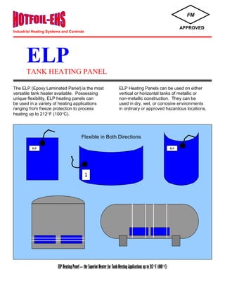
The ELP (Epoxy Laminated Panel) is the most versatile tank heater available. Possessing unique flexibility, ELP heating panels can be used in a variety of heating applications ranging from freeze protection to process heating up to 212 deg. F (100 deg. C).

Recomendados
Recomendados
Mais conteúdo relacionado
Mais procurados
Mais procurados (20)
Semelhante a Epoxy Laminated Tank Heater Panels
Semelhante a Epoxy Laminated Tank Heater Panels (20)
Último
Último (20)
Epoxy Laminated Tank Heater Panels
- 1. ELP TANK HEATING PANEL The ELP (Epoxy Laminated Panel) is the most ELP Heating Panels can be used on either versatile tank heater available. Possessing vertical or horizontal tanks of metallic or unique flexibility, ELP heating panels can non-metallic construction. They can be be used in a variety of heating applications used in dry, wet, or corrosive environments ranging from freeze protection to process in ordinary or approved hazardous locations. heating up to 212F (100C). ELP Heating Panel – the Superior Heater for Tank Heating Applications up to 212F (100C) FM APPROVED Flexible in Both Directions ELP ELP ELP Industrial Heating Systems and Controls
- 2. The ELP panel is the heater for the 21st century. Its unique epoxy-fiberglass construction utilizes foil resistance elements that are synonymous with our proven range of products. The low watt density of this heating panel, together with its low mass, provide unequaled thermodynamic performance. The ELP heater is heat and pressure cured to give its robust qualities such as strength, durability, heat, water, and corrosion resistance. All panels have 10'-0" long waterproof cold leads. ELP Specifications Model: ELP-1 ELP-2 ELP-3 ELP-4 ELP-5 ELP-6 ELP-7 ELP-8 ELP-9 Size (inches) Power (watts) Voltage (volts) D.C. Resistance* (ohms) Weight (lbs.) Area (sq.ft.) Power Density (w/sq.ft.) Current (amps) 24 x 18 275 120 52 3 3 92 2.3 48 x 18 550 120 26 6 6 92 4.6 48 x 24 400 120 36 8 8 50 3.3 48 x 36 1100 120 13 12 12 92 9.2 48 x 40 480 120 30 13 13.3 36 4 48 x 18 550 240 105 6 6 92 2.3 48 x 24 400 240 144 8 8 50 1.7 48 x 36 1100 240 52 12 12 92 4.6 48 x 40 480 240 120 13 13.3 36 2 Maximum Exposure Temperature……… 250F / 121C Cold Lead ………………….. #16awg cable, 105C, 600V, 13A Minimum Installation Temperature …… -40F / -40C Minimum Bending Radius …. 2 feet Option - Conduit Hub (-H) ……………… 1/2" NPT, Aluminum Resin System: The resin system is based on a BROMINATED BISPHENOL A epoxide resin cured with DICYANDIAMIDE and BENZYLDIMETHYLAMINE. Fire Retardancy: The resin system is approved by Underwriters Laboratory (File E 53727) to UL 94 V-0 flammability rating when used in NEMA grade FR4 laminates. * Resistance (@70F) +/- 10%. 3-core cold lead, 10ft. typical epoxy molded termination conduit hub, optional for ordinary areas mandatory for classified areas aluminum ground shield multi-layer epoxy resin and fiberglass construction foil heating elements
- 3. Heating System Design Guide To determine the amount of heaters required for a typical tank heating application, follow these easy steps: 1. Calculate total Tank Surface Area Tank Area = 3.142 x D x (R+H) Where, D = tank diameter R = tank radius H = tank height (or length) 2. Find Basic Heat Loss from Table 1. 3. Find Insulation Correction Factor from Table 2. 4. Find Windage Factor from Table 3. 5. Add 10% for vertical tanks standing on a concrete base - 1.1 multiplier. 6. Add 10% for safety - 1.1 multiplier. 7. Calculate the Total Heat Loss, Multiply steps: 1x2x3x4x5x6 = Total Heat Loss (Heat Required). 8. Select a suitable ELP Heating Panel for the application from the ELP Specifications. 9. Find the ELP Load Factor at the application temperature from the ELP Load Factor Graph. 10. Calculate selected ELP heater wattage at the application temperature. Multiply Load Factor from step 9 by selected ELP wattage. 11. Calculate selected ELP heater wattage due to voltage difference from design. Multiply the heater wattage (step 10) by the corresponding voltage factor from Table 4. 12. Determine the quantity of ELP Heating Panels required. Divide Total Heat Loss/Requirement by the actual ELP wattage. Divide step 7 by step 11. Note: If this result's fraction exceeds 0.1, increase the quantity of ELP Heaters by one (to next higher whole number). Table 1 - Basic Heat Losses (W/sq.ft.) Delta T (F) Insulation Thickness (In) 1 1 1/2 2 3 4 50 75 100 3.6 5.4 7.2 2.3 3.5 4.8 1.7 2.6 3.5 - 2.0 2.6 - - - 125 150 175 9.0 10.9 12.9 6.2 7.6 9.0 4.5 5.5 6.6 3.3 4.0 4.7 - 3.1 3.7 200 225 250 14.8 - - 10.4 11.9 13.5 7.7 8.9 10.1 5.4 6.2 7.0 4.3 4.9 5.5 Table 2 - Thermal Insulation Correction Factors Thermal Insulation Type Insulation Factor Polyurethane Fiberglass Foamed Plastic Polystyrene Calcium Silicate Cellular Glass 0.7 1.0 1.1 1.2 1.5 1.6 Heating System Design Example Maintain a 12'-0" diameter by 20'-0" high vertical tank at 80F, when the minimum ambient temperature is -20F and wind is 25mph. Tank will be insulted with 2" thick polyurethane foam insulation and is mounted on a concrete base. Heaters will operate on 220VAC. 1. To calculate total Tank Surface Area in sq.ft., multiply the following: Tank Area=3.142 x D x (R+H)=3.142 x 12' x (6'+20')=980sq.ft. where D = 12', R = 6', H = 20' 2. The Basic Heat Loss from Table 1 for Delta T = 100F, (80F - (-20F)), and 2" thermal insulation is 3.5watts/sq.ft. 3. The Insulation Correction Factor from Table 2 for Polyurethane thermal insulation is 0.7. 4. The Windage Factor from Table 3 for 25mph wind velocity is 1.12. 5. To add 10% for vertical tanks standing on a concrete base multiply by 1.1. 6. To add 10% for safety - multiply by 1.1. 7. To calculate the Total Heat Loss (Heat Required), multiply steps 1 through 6. 8. For this 220VAC application, an ELP-6 (48" x 18", 550W, 240V) is a suitable choice. 9. To find the ELP Load Factor at 80 F from the Graph, follow 80F vertical line up to the graph and then horizontally across to the left and read the value of 0.95. 10. To calculate actual ELP wattage, multiply 550W x 0.95 = 523W. 11. Since the supply voltage is 220VAC while heater design is 240VAC, multiply heater wattage (523W) from step 10 by the corresponding voltage factor 0.84 from Table 4: 523W x 0.84 = 439W. 12. To determine the total quantity of ELP Heating Panels required for this heating system, divide step 7 by step 11: Quantity of ELP Panels = 3254W 439W = 7.4 Panels. Since the fraction exceeds 0.1, the total quantity of ELP tank heating panels required is 8. Graph – ELP Load Factor vs. Application Temperature Table 4 - Voltage Factors Table 3 - Windage Factors Wind Velocity (mph) W.F. 0 - 10 11 - 20 21 - 30 31 - 50 1.03 1.07 1.12 1.17 Supply Voltage V.F. 120 1.00 115 0.92 110 0.84 240 1.00 220 0.84 208 0.75 40 60 80 100 120 140 160 180 200 220 1.0 0.9 0.8 0.7 APPLICATION TEMPERATURE (F) L O A D F A C T O R The ELP heating panel possesses a feature of being able to “load shed”. ELP heater decreases its power output as its temperature increases. Use the above graph to determine each heater’s wattage at the application temperature.
- 4. ELP TANK HEATING PANEL Notes: 1. Non-metallic tanks, lined tanks, tanks containing heat 3. All applications drawing more than 20amps sensitive or viscous materials require special of current, use multi-phase voltage, alarm, or considerations. Consult HOTFOIL. monitoring, etc. require special control equipment - consult HOTFOIL. 2. Most typical heating applications drawing less than 20 amps of current may be controlled directly by one or 4. For tank "heat up" applications - consult HOTFOIL. two 20amp rated thermostats. 5. Hotfoil recommends the use of an override thermostat or controller on all applications. Installation: ELP heating panels are quick and easy to install, require no special tools or skills. Heaters are usually installed by banding them to the tank with metal bands or polyester straps. Installation of several ELP heating panels takes only a few minutes. Refer to ELP Installation Instructions for full details. ELP Ordering Information: ELP – X – X – 10 FM Approvals Class I, Division 2, Groups B, C, D Class II, Divisions 1 & 2, Groups F, G Class III, Divisions 1 & 2 Ordinary Areas ** Hubs - “A” Aluminum (Standard) “SS” Stainless Steel “P” PVC Coated ** Note: Hubs are supplied as standard on ELP Panels when used in hazardous locations. ELP Model Number Option – With Hub “H” ** No Hub - Standard Standard 10’-0” 3-core lead unless otherwise requested FM APPROVED ELP.LT.R1 Hotfoil-EHS, Inc. 2960 East State Street Extension Hamilton, NJ 08619 Tel: (609) 588-0900 Fax: (609) 588-8333 www.HOTFOILEHS.com