Ntpc (national thermal power corporation) sipat mechanical vocational training report 1 haxxo24 i~i
1. Summer Training Project Report
On
“Coal-Fired Steam Power Plants”
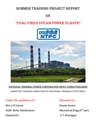
NATIONAL THERMAL POWER CORPORATION SIPAT (CHhATTISGARH)
(SUBMITTED TOWARDS COMPLETION OF VOCATIONAL TRAINING AT NTPC SIPAT)
Under the guidance of:- Submitted by:-
Shri U.R.Verma Dinesh Kumar
DGM, Boiler Maintenance Mechanical Engg.(4th
sem)
Department I.I.T.Kharagpur
2. Declaration by Student
I hereby declare that work entitled “Summer training project report”,
submitted towards completion of vocational training after 2nd year of
B.Tech (Mechanical Engineering) at Indian Institute of Technology
Kharagpur comprises of my original work pursued under the supervision
of Guides at NTPC Sipat.
The results embodied in this report have not been submitted to any other
Institute or University for the fulfillment of any other curriculum.
Name:- Dinesh Kumar
Roll No:- 10ME10016
B.tech (4th
Semester)
I.I.T. Kharagpur
West Bengal
3. CERTIFICATE
This is to certify that Mr. Dinesh Kumar of Indian Institute of
Technology Kharagpur has undergone Vocational training from
21/05/2012 to 18/06/2012 at National Thermal Power Corporation,
Sipat in the Boiler Maintenance Department and has made the project
under my guidance.
Project Guide
Shri U.R.Verma
Deputy General Manager
Boiler Maintenance department
4. Acknowledgement
“It is not possible to prepare a project report without the assistance &
encouragement of other people. This one is certainly no exception.”
On the very outset of this report, I would like to extend my sincere and
heartfelt obligation towards all the personages who have helped me in this
endeavor. Without their active guidance, help, cooperation and
encouragement, I would not have made head way in the project.
First and foremost, I would like to express my sincere gratitude to my
project guide, Shri U.R.Verma .
I was privileged to experience a sustained enthusiastic and involved
interest from his side. This fuelled my enthusiasm even further and
encouraged me to boldly step into what was a totally dark and unexplored
expanse before me. He always fuelled my thoughts to think broad and out
of the box.
I would also like to thank Mr. Dibtendu Mandal who, instead of his busy
schedule, always guided me in right direction to head and also helped in
understanding the Rotary parts of Boiler.
Last but not least, I would like to thank Mr. Girish Choudhary and Mr.
Rishabh Kapoor for teaching and helping me in every sphere of rotary and
pressure parts respectively.
I would like to thank Employee development Centre for organizing and
permitting the Vocational training program for us.
Thanking you,
Dinesh Kumar
5. POWER SECTOR IN INDIA
Power sector plays a very vital role in overall economic growth of any country. For Indian perspective, the
power sector needs to grow at the rate of at least 12% to maintain the present GDP growth of about 8%. As per
the Ministry of Power report, the per capita consumption of electricity is expected to grow to 1000 kWh / year
by the year 2012 which during the year 2004 – 2005 was 606 kWh/year. To meet the per capita consumption of
1000 kWh/year by the year 2012 the capacity augmentation requirement is about 1,00,000 MW. Presently there
is a significant gap between the demand and supply of power. The energy deficit is about 8.3% and the power
shortage during the peak demand is about 12.5%.
NATIONAL THERMAL POWER CORPORATION LIMITED
NTPC Limited is the largest power generation company in India. Forbes Global 2000 for 2009 ranked it 317th
in the world. It is an Indian public sector company listed on the Bombay Stock Exchange although at present the
Government of India holds 84.5% of its equity. With a current generating capacity of 32,694 MW, NTPC has
embarked on plans to become a 75,000 MW company by 2017. It was founded on November 7, 1975 with
100% ownership of the Central government. In 1997, Government of India granted NTPC status of “Navratna‟
being one of the nine jewels of India, enhancing the powers to the Board of Directors. NTPC became a
Maharatna company in May, 2010, one of the only four companies to be awarded this status.
NTPC‟s core business is engineering, construction and operation of power generating plants and providing
consultancy to power utilities in India and abroad.
The total installed capacity of NTPC in India is as follows at present:
NO. OF PLANTS CAPACITY (MW)
NTPC Owned
Coal 15 25,375
Gas/Liquid Fuel 7 3,955
Total 22 29,330
Owned By JVs
Coal & Gas 5 3,364
Total 27 32,694
NTPC has been operating its plants at high efficiency levels. Although the company has 18.10% of the total
national capacity, it contributes 28.60% of total power generation due to its focus on high efficiency.
NTPC SIPAT
Location : 22 Km from Bilaspur, CG
Capacity : 3 X 660 MW Stage-I and 2 X 500 MW Stage-II
|~|
6. Water Source : From Hasdeo right bank canal
Coal Mines : Dipika Mines of SECL Korba.
Coal Transport : By dedicated MGR (42 Kms)
Highlights:
* Super Critical Technology first time in India
*765 KV Transmission System first time in India
*100 Mtr. wide peripheral green belt around the project
*Submerged ash dyke
*State-of-the-art Technology for Environmental Management
NTPC Sipat Super Thermal Power Project is a cynosure of power generation in India. It is a priceless gem of
mineral rich state of Chhattisgarh. Being in the vicinity of Bilaspur, the second largest city of Chhattisgarh and
at the vertex of transport arteries adds to its majestic aura.
Total installed capacity of the Sipat Super Thermal Power Project is 2980 MW (Stage I-660 X 3 & Stage II-500
X 2 MW). Plant‟s water requirement is catered by Hasdeo right bank canal. It gets coal supply from Dipika
mines of SECL, Korba. The coal is transport via dedicated MGR system of total length 42 km.
Sipat Super Thermal Power Project has many accolades to its credits. Being a pioneer of Super Critical
Technology in India and transmission system of 766 kV for the first time in India are the most unique attributes.
Addressing this most pressing need of the hour, i.e. our environment, Sipat Project has 100 meter wide
peripheral green belt, submerged ash dykes and state-of-the art technology for environment management.
BASIC POWER PLANT CYCLE
RANKINE CYCLE
The basic principle of the working of a thermal power plant is quite simple. The fuel used in the plant is burned
in the boiler, and the heat thus generated is used to boil water which is circulated through several tubes, and the
steam that is generated is then used to drive a turbine, which in turn is coupled with a generator, which then
produces electricity.
The working of the coal based plant is based upon a modified Rankine cycle. The Rankine cycle is represented
most commonly on a temperature-entropy diagram. The topmost point is known as the critical point.
|~|
8. Typical diagram of a thermal power plant :-
1. Cooling tower 10. Steam Control valve 19. Superheater
2. Cooling water pump 11. High pressure steam turbine 20. Forced draught (draft) fan
3. transmission line (3-phase) 12. Deaerator 21. Reheater
4. Step-up transformer (3-phase) 13. Feedwater heater 22. Combustion air intake
5. Electrical generator (3-phase) 14. Coal conveyor 23. Economiser
6. Low pressure steam turbine 15. Coal hopper 24. Air preheater
7. Condensate pump 16. Coal pulverizer 25. Precipitator
8. Surface condenser 17. Boiler steam drum 26. Induced draught (draft) fan
9. Intermediate pressure steam
turbine
18. Bottom ash hopper 27. Flue gas stack
MAJOR SUB-SYSTEMS OF A POWER PLANT:-
1) COAL HANDLING PLANT (C.H.P):- Coal Handling Plant is the place where processing of raw
coal occurs before it is transferred to the bunkers. CHP enhances the calorific value of coal and makes its
transportation cost lower and easier. The coal is provided by the Deepika mines under the S.E.C.L, with the
help of a dedicated merry-go-round (MGR).When the coal is supplied at the CHP, the coal is moved along the
track hopper towards the crusher, where the lumps of coal are crushed into 20 mm sized particles, from where
they may be stored in the stack-yard, or sent to the bunkers before being fed into the boilers.
Salient Features of CHP Stage-I :
• Conveyor Capacity – 2000/2600MTPH
• Conveyor Width – 1600 mm
• Paddle Feeder cap- 1500MTPH
• Crusher Capacity- 1250MTPH
• SR Capacity-2000mtph
• Inter Connection Between ST-1&ST-2
• PLC Based Operation
Salient Features of CHP Stage-II :
• Conveyor Capacity – 2600 MTPH
9. • Conveyor Width - 1800 mm
• Conveyor Speed – 3.2 m/sec
• Paddle Feeder capacity- 1950 MTPH
• VGF Capacity – 1625 MTPH
• Crusher Capacity – 1625 MTPH
• STACKER /RECLAIMER Capacity- 2600MTPH
• CCTV compatible to integrated FIRE ALARM SYSTEM
• PLC Based Operation
• Lifts at Crusher House & TP19
• Inter Connection between ST-1&ST-2
10. 2) MILL: The coal particles are ground into finer sized granules. The coal which is stored in the bunker is
sent into the mill, which is primarily a ball type, in which a drum contains a ball, and when the drum rotates the
ball also does, and this causes the coal particles caught in between to be ground.
After grinding, the coal is then passed through a desired size of mesh, so that any coal particle not properly
ground is not allowed through. Then the coal is forced by a blast of air coming from the primary air fans to
enter the boiler. Coal is fed to the mills from the bunkers via the raw coal feeders.
Another type of mill is the ball and race mill, in which the coal passes between the rotating elements again and
again until it has been pulverized to the desired degree of fineness. However, there is greater wear in this mill as
compared to other pulverizers. There are 10 mills located adjacent to the furnace. These mills pulverise coal to
the desired fineness to be fed to the furnace for combustion. Capacity of 1 mill is 62.9 tonnes/hr.
Factors affecting bowl mill performance:-
Size of raw coal
Raw coal grindability
Raw coal moisture content
Pulverised fuel fineness
Mill internals wear and poor quality of raw coals.
Mill drive system mainly consists of three components namely mill motor, mill coupling and mill gear box. Mill
coupling comprises of Bibby coupling (present on the motor side) and gear coupling (present on the gear box
side). In a bowl mill, the major grinding element grinding roll is conical in shape and is three in number per mill
11. INTERIOR OF BOWL MILL
3) WATER TREATMENT PLANT: Since water is the basic requirement for the production of the
working substance, it is necessary to have an arrangement to provide water which is not contaminated by
unwanted materials. For this a water treatment unit is provided which receives water from a source, then de-
mineralizes it and finally after further treatment, is fed into a boiler feed pump. This is a unit which
consumes relatively low power compared to other units in a power plant. Some of the systems involved in
the treatment of water are de-mineralization plant, raw water pump house, clarification plant and many
others.
The type of water used is different for different purposes. The process of cooling requires raw water,
whereas steam formation, and many other major processes require de-mineralized water.
De-mineralization plants consist of cation, anion and mixed bed exchangers. The final water from this stage
consists of hydrogen ions and hydroxyl ions which is the chemical composition of pure water.
4) BOILER: A boiler is the central component of a power plant, and it is the unit where the steam
required for driving the turbine is generated. The heat absorbing parts subject to internal pressure in a boiler
are called as pressure parts. The main pressure parts in a boiler are Drums, Water walls, Super heaters, Re
heaters, Economisers and valves & fittings. The Drum, Down comers, water wall headers and water walls
forms the circulation system and cover the furnace zone. The components of Boiler and their functions are
as follows :-
a)Boiler Drum: The drum provides the necessary space for locating the steam separating equipment
for separation of steam from mixture of steam and water. It also serves as a reservoir for the supply of water
12. to circulation system to avoid possible starvation during operation. The drum is filled with water coming
from the economizer, from where it is brought down with the help of down-comer tubes, entering the
bottom ring headers. From there they enter the riser, which carries the water (which now is a liquid-vapor
mixture), back to the drum. Now, the steam is sent to be superheated.
For a 660 MW plant, the boiler does not employ any drum; instead the water and steam go directly into the
super heater.
Drum is located at 78 m elevation in the boiler front. Water enters the drum from the bottom via three ECO
links. Drum has connections for Chemical dozing, Emergency drain, Continuous blow down & sample
cooler tapping. Total 5 no. of vents and 6 no of safety valves, 3 on each side are provided on the drum.
Total 18 MTM thermocouples, 6 no of level transmitters, 3 pressure transmitters and 3 pressure indicators
are provided on the drum. There are 2 no of Electronic Water Level Indicators (EWLI) and 1 no of Direct
Water Level Gauge (DWLG) provided on each side of the drum.
b) Economiser: The economizer is a tube-shaped structure which contains water from the boiler feed
pump. This water is heated up by the hot flue gases which pass through the economizer layout, which then
enters the drum. The economizer is usually placed below the second pass of the boiler. As the flue gases are
being constantly produced due to the combustion of coal, the water in the economizer is being continuously
being heated up, resulting in the formation of steam to a partial extent. Feedwater (FW) from Feed Regulating
Station (FRS) with parameters P=200.2 ksc, T=255.2 C travels to Economiser inlet header located at Elevation
44.2m through ECO feed line. ECO feed line connects to the ECO inlet header at the right side of boiler
backpass. One NRV and motorised ECO stop valve is provided in the ECO feed line just before it connects to
the ECO inlet header. One no of drain is also provided in the ECO feed line just after the ECO stop valve. The
drain is connected to the water wall (WW) drain header located at „0‟ meter. One no of ECO recirculation line
is provided after the ECO stop valve which connects to the rear ring header.
ECO inlet header:- It is arranged parallel to the drum at the bottom of backpass middle at the elevation 44.2m.
One no of drain is provided in the header. The drain is connected to the WW drain header.192 x 3 loose tubes
connect the ECO inlet header to the ECO lower assembly.
ECO outlet header:- Located at the Elevation 57.5m, it is arranged parallel to the drum in backpass. Two
links from ECO outlet header project out from back pass side walls and join again at the boiler front at 66.5m
elevation. From this junction three pipes carry feed water to the drum.
c) CC Pumps:- Six no. of Downcomers carry feedwater(FW) from drum to suction manifold of CC
Pumps located at 29.5m elevation. 3 no. of suction spool pieces carry FW from suction manifold to the 3 no. of
CC Pumps located at 23.3m elevation. The pumps are of double discharge type. Parameters at the pump:
P=197.4 ksc, 359.1 C and flow/pump= 3135 cu.m/hr. Connections to the pump include HP fill and purge lines,
LP coolant lines. Inter tie line connecting discharges of all pumps. One equalising line from the center pump
suction connects to the intertie line.
Two no of coolers are also provided: HP Fill and Purge Cooler and LP Cooler for motor.
Source of HP fill & Purge is from 1. Feed line (for periodic use) 2. From Condensate system (low pressure fill
source).
Source of LP coolant supply: 1. Normal supply 2. From Emergency tank
13. d) Bottom Ring Header:- The 6 no. of CC pump discharge lines carry FW to the bottom ring header
located at 10.6m. Ring header is provided with one no of blow off line from front ring header which is
connected to the IBD Tank. One no of drain is also provided from the rear ring header which is connected to the
WW drain header. ECO recirculation line also connects to the rear ring header.
e) Water walls:- 331 tubes each from front & rear ring headers form the front, rear and corner water
walls. There are 25 tubes in each corner wall & 281 tubes in front and rear water walls each. Front water wall is
integral with the corners 1 & 4 and rear wall is integral with the corners 2 & 3. Each side water wall (Left &
Right) has 224 tubes. All water wall tubes are rifled from inside except the „S‟ panel tubes. Total no of tubes
originating from Bottom ring header = 331x2 + 224x2 = 1110.
In a 500 MW unit, the water walls are of the vertical type, and have rifled tubing while in 600 MW, the
water walls are spiral type and have smooth tubing.
F) De-aerator : A de-aerator is a device that is widely used for the removal of air and other dissolved
gases from the feedwater to steam-generating boilers.
There are two basic types of deaerators, the tray-type and the spray-type:
The tray-type (also called the cascade-type) includes a vertical domed deaeration section mounted on
top of a horizontal cylindrical vessel which serves as the deaerated boiler feedwater storage tank.
The spray-type consists only of a horizontal (or vertical) cylindrical vessel which serves as both the
deaeration section and the boiler feedwater storage tank.
14. G) Super-Heaters: Super-heaters are used to raise the steam temperature above the saturation
temperature by absorbing heat from flue gas to increase the cycle efficiency.
Super heating takes place in three stages. In the first stage, the steam is sent to a simple super heater, known as
the low temperature super heater, after which the second stage consists of several divisional panels. The final
stage involves further heating in a Platen super heater, after which the steam is released for driving the turbine.
After the HP stage of the turbine the steam is re-heated and then again released.
Superheating is done to increase the dryness fraction of the exiting steam. This is because if the dryness fraction
is low, as is the case with saturated steam, the presence of moisture can cause corrosion of the blades of the
turbine. Super heated steam also has several merits such as increased working capacity, ability to increase the
plant efficiency, lesser erosion and so on. It is also of interest to know that while the super heater increases the
temperature of the steam, it does not change the pressure. There are different stages of superheaters besides the
sidewalls and extended sidewalls. The first stage consists of LTSH(low temperature superheater), which is
conventional mixed type with upper & lower banks above the economiser assembly in rear pass. The other is
Divisional Panel Superheater which is hanging above in the first pass of the boiler above the furnace. The third
stage is the Platen Superheater from where the steam goes into the HP turbine through the main steam line. The
outlet temperature & pressure of the steam coming out from the superheater is 540 degrees Celsius & 157
kg/cm2
.
5) TURBINES : The turbine employed in a thermal power plant is a steam turbine. The initial steam is
admitted ahead of the blading via two main stop and control valve combinations. The turbine unit of any
thermal power plant is not a single stage operation, rather it consists of three stages:
High Pressure Turbine Stage (HPT Stage): This stage takes place immediately after the Platen super heater
stage. This is the first stage of the turbine operation. Its outer casing is of a barrel type and has neither a radial
nor an axial flange. The inner casing is axially split and supported so as to be free to move in response to
thermal expansion.
Intermediate Pressure Turbine Stage (IPT Stage): After the HPT stage, the steam gets saturated and,
consequently, gets cooled. It is, therefore, first sent back to the boiler unit to be reheated, after which it is sent to
the IPT stage. Its section is of double flow construction with horizontally split casings.
Low Pressure Turbine Stage (LPT Stage): After the IPT, the steam gets cooled to an intermediate extent, thus
directly entering the LPT, where it gets saturated. Its casing is of the three-shell design. After this stage the
water enters the condenser, which is connected to a condensate extraction pump.
A turbine assembly consists of a rotor assembly on whose circumference is attached a series of vanes, a bearing
assembly to support the shaft, a metallic casing surrounding the blades, nozzle, rotor etc, a governor to control
the speed and a lubrication system.
The shaft of the turbine is connected to the generator. The purpose of the generator is to convert the
mechanical shaft energy it receives from the turbine into electrical energy. Steam turbine driven AC
synchronous generators (alternators) are of two or four pole designs. These are three phase machines offering
economic advantages in generation and transmission. Large generators have cylindrical rotors with minimum
15. heat dissipation surface and so they have forced ventilation to remove the heat. Such generators generally use an
enclosed system with air or hydrogen coolant. The gas picks up the heat from the generator and gives it up to
the circulating water in the heat exchanger.
Every turbine, except the LPT, has a stop valve and a regulating valve attached to it. The stop valve is used to
stop the flow of steam, whenever required, whereas the regulating valve is also a kind of a flow controlling
device. Each turbine also has an inlet and an outlet pipe for the steam to enter and exit, respectively. Between
the HPT-IPT combine and the IPT-LPT combine is attached a bearing assembly. It is constructed using a cross
around pipe.
After the steam leaves the turbine, it enters the condenser . The condenser is meant to receive the steam from
the turbine, condense it and to maintain a pressure at the exhaust lower than the atmospheric pressure. The
condenser is an important unit and some of the auxiliaries required for it to function properly are the cooling
water supply pump, the condensate extraction pump, feed water pump and the air removal pump.
6) ASH HANDLING AND DISPOSAL: There are two types of ash handling methods: dry ash
handling and wet ash handling. Dry ash handling is carried out by storing the ash deposited in large pits,
whereas in the wet ash handling method, the ash is deposited into large reservoirs or ponds.
16. 1. Wet mode:--Ash evacuated from ESP hoppers through vacuum pumps & fed to wetting head (vacuum
system) and collector tank units where ash is mixed with water & resultant slurry is discharged to slurry
trenches.
2. Dry mode:--Ash evacuated from ESP hoppers through vacuum pumps & collected in Buffer hoppers & Air
lock tank, is transported to storage silo by compressed air (pressure conveying system) through pressure
conveying pipe lines.
Components of wet fly ash system
1. ESP hopper
2. Plate valve for isolation .
3. Material Handling Valve (MHV)
4. Piping up to wetting head
5. Wetting head
6. Air washer
7. Vacuum pump
17. Auxiliaries in a power plant
1) PA FANS: The primary air fans are used to carry the pulverized coal particles from the mills to the
boiler. They are also used to maintain the coal-air temperature. The specifications of the PA fan used at
the plant under investigation are: axial flow, double stage, reaction fan.
The PA fan circuit consists of:
a) Primary air path through cold air duct
b) Air pre-heater
c) Hot air duct
d) Mills
The model no. of the PA fan used at NTPC Sipat is AP2 20/12, where A refers to the fact that it is an
axial flow fan, P refers to the fan being progressive, 2 refers to the fan involving two stages, and the
numbers 20 and 12 refer to the distances in decimeters from the centre of the shaft to the tip of the
impeller and the base of the impeller, respectively. A PA fan uses 0.72% of plant load for a 500 MW
plant.
2) FD FANS: The forced draft fans, also known as the secondary air fans are used to provide the
secondary air required for combustion, and to maintain the wind box differential pressure. Specifications
of the FD fans are: axial flow, single stage, impulse fan.
The FD fan circuit consists of:
a) Secondary air path through cold air duct
b) Air pre-heater
c) Hot air duct
d) Wind box
The model no. of the FD fan used at NTPC Sipat is AP1 26/16, where the nomenclature has been
described above. FD fans use 0.36% of plant load for a 500 MW plant.
3) ID FANS: An induced fan circuit consists of
a) Flue gas through water walls
b) Super heater
c) Re-heater
d) Platen super heater
e) Low temperature super heater
18. f) Air pre-heater
g) Electrostatic precipitator
The main purpose of an ID fan is to suck the flue gas through all the above mentioned equipments and to
maintain the furnace pressure. ID fans use 1.41% of plant load for a 500 MW plant.
4) SCANNER AIR FAN: Scanner air fan is used to provide air to the scanner. For a tangentially fired
boiler, the vital thing is to maintain a stable ball of flame at the centre. A scanner is used to detect the
flame, to see whether it is proper and stable. The fan is used to provide air to the scanner, and it is a
crucial component which prevents the boiler from tripping
5) SEAL AIR FAN: The seal air fan is used near the mill to prevent the loss of any heat from the coal
which is in a pulverized state and to protect the bearings from coal particle deposition.
6) AIR PRE-HEATERS: Air pre-heaters are used to take heat from the flue gases and transfer it to the
incoming air. They are of two types:
a) Regenerative
b) Recuperative
The APH used at NTPC Sipat is a Ljungstrom regenerative type APH. A regenerative type air pre-
heater absorbs waste heat from flue gas and transfers this heat to the incoming cold air by means of
continuously rotating heat transfer elements of specially formed metal sheets. A bi-sector APH
preheats the combustion air. Thousands of these high efficiency elements are spaced and compactly
arranged within sector shaped compartments of a radially divided cylindrical shell called the rotor. The
housing surrounding the rotor is provided with duct connections at both ends, and is adequately sealed
by radial and axial sealing members forming an air passage through one half of the APH and a gas
passage through the other.
As the rotor slowly revolves the elements alternately pass through the air and gas passages; heat is
absorbed by the element surfaces passing through the hot gas stream, then as the same surfaces pass
through the air stream, they release the heat to increase the temperature of the combustion of process
air.
A single APH is divided into 4 parts: 2 PAPHs and 2 SAPHs. The P and S refer to primary and
secondary respectively. Each part is divided into two slots, one slot carrying the primary/secondary air,
and the other slot carrying the hot flue gases coming from the 2nd
pass of the boiler. The PAPH is
connected to the mills, whereas the SAPH is connected to a wind box.
19. 7) ELECTROSTATIC PRECIPITATORS: They are used to separate the ash particles from the
flue gases. In this the flue gas is allowed into the ESP, where there are several metallic plates placed at a
certain distance from each other.
When these gases enter, a very
high potential difference is
applied, which causes the gas
particles to ionize and stick to the
plates, whereas the ash particles
fall down and are collected in a
hopper attached to the bottom of
the ESP. The flue gas is allowed to
cool down and is then released to
the ID fan to be sent to the
chimney.
Indian coal contains about 30% of ash. The hourly consumption of coal of a 200 MW unit is about 110
tons. With this, the hourly production of ash will be 33 tons. If such large amount of ash is discharge in
atmosphere, it will create heavy air pollution thereby resulting health hazards. Hence it is necessary to
precipitate dust and ash of the flue gases.
Precipitation of ash has another advantage too. It protects the wear and erosion of ID fan.
To achieve the above objectives, Electrostatic Precipitator (ESP) is used. As they are efficient in
precipitating particle form submicron to large size they are preferred to mechanical precipitation.
Construction
An ESP has series of collecting and emitting electrons in a chamber collecting electrodes are steel plates
while emitting electrodes are thin wire of 2.5mm diameter and helical form. Entire ESP is a hanging
structure hence the electrodes are hung on shock bars in an alternative manner.
It has a series of rapping hammer mounted on a single shaft device by a motor with the help of a gear box
at a speed of 1.2 rpm. At the inlet of the chamber there are distributor screens that distributes the gas
uniformly throughout the chamber.
There are transformer and rectifiers located at the roof of chamber. Hopper and flushing system form the
base of chamber.
Working:
Flue gases enter the chamber through distributor screen and get uniformly distributed. High voltage of
about 40 to 70 KV form the transformer is fed to rectifier. Here ac is converted to dc. The negative
20. polarity of this dc is applied across the emitting electrode while the positive polarity is applied across the
collecting electrodes. This high voltage produces corona effect negative (–ve) ions from emitting
electrode move to collecting electrode. During their motion, they collide with ash particles and transfer
their charge. On gaining this charge, ash particles too move to collecting electrode and stock to them.
Similar is the case with positive (+ve) ions that moves in opposite direction.
The rapping hammers hit the shock bars periodically and dislodge the collected dust from it. This dust fall
into hopper and passes to flushing system. Here it is mixed with water to form slurry which is passed to
AHP.
Efficiency of ESP is approximately 99.8%.
Theory of Precipitation
Electrostatic precipitation removes particles from the exhaust gas stream of Boiler combustion
process. Six activities typically take place:
Ionization - Charging of particles
Migration - Transporting the charged particles to the collecting surfaces
Collection - Precipitation of the charged particles onto the collecting surfaces
Charge Dissipation - Neutralizing the charged particles on the collecting surfaces
Particle Dislodging - Removing the particles from the collecting surface to the hopper
Particle Removal - Conveying the particles from the hopper to a disposal point
The ash produced on the combustion of coal is collected by ESP. This ash is now required to be disposed
off. This purpose of ash disposal is solved by Ash Handling Plant (AHP).
8) CONDENSATE EXTRACTION PUMP : The condensate extraction pump (CEP) is a
centrifugal, vertical pump, consisting of the pump body, the can, the distributor housing and the driver lantern.
A rising main of length depending upon NPSH available, is also provided. The pump body is arranged
vertically in the can and is attached to the distributor body with the rising main. The rotor is guided in bearings
lubricated by the fluid pumped, is suspended from the support bearing, which is located in the bearing pedestal
in the driver lantern. The shaft exit in the driver lantern is sealed off by one packed stuffing box.
Casing
It is split on right to the shaft and consists of suction rings and 4 no. of guide vane housing. Casing components
are bolted together and sealed off from one another by 'O' rings. For internal sealing of individual stages, the
casing components are provided with exchangeable casing wear rings in the arc of impeller necks. In each
guide vane casing, a bearing bush is installed to guide the shaft of pump.
Rotor
The pump impellers are radially fixed on the shaft by keys. The impellers are fixed in position axially by the
bearing sleeves and are attached to the shaft by means of impeller nut. Impellers are single entry type, semi-
axial and hydraulically balanced by means of balance holes in the shroud and throttle sections at suction and
discharge side. A thrust bearing located in the motor stool absorbs residual axial thrusts.
21. Bearings
In each guide vane housing the shaft is guided by a plain bearing. These bearings do not absorb any axial forces.
Pump bearings consist of bearing sleeve, rotating with the shaft and bearing bush, mounted in guide vane
housing. The intermediate shaft is guided in bearing spider and shaft sleeve. The arrangement of bearing
corresponds to the bearings of pump shaft. They are lubricated by condensate itself. A combined
thrust and radial bearing is installed as support bearing to absorb residual thrust. Axial load is transmitted to the
distributor casing via the thrust bearing plate, thethrust bearing and bearing housing. A radial bearing attached
to the bearing is installed in an enclosed housing and is splash lubricated by oil filled in the enclosure. Built-in
cooling coils in the bath and cooling water control oil temperature.
9) BOILER FEED PUMP: The auxiliary component which consumes the maximum amount of power
earmarked for such purposes is the boiler feed pump. At NTPC Sipat, the auxiliaries consume about 7%
of the plant load. The boiler feed pump is used to feed water to the boiler, as the name suggests, through
the economizer. The BFP is fed from the CEP and the water source. The BFP is of two types
a) TDBFP: turbo-driven boiler feed pump.
b) MDBFP: motor driven boiler feed pump.
The boiler feed pump is fed water from the condensate extraction pump. The condensate extraction pump
collects the condensate from the condenser. Then the condensate is further cooled by being sent into the gland
steam coolers, after which it is sent into the BFP.
10) COOLING TOWERS: Cooling towers are used to remove the heat from the condensers. In this
cooling water is discharged to the condenser with the help of a cooling water pump (CW pump). This
water enters the condenser through several tubes. Steam entering the condenser from the turbine after
expansion further loses heat and condenses, while the water circulating inside the tube gains heat and
goes back to the cooling tower. Inside the tower is a cooling fan which takes the heat from this batch of
water, which is then sent back again for the cycle to be repeated. It is hence known as a regenerating
cycle.
Cooling towers are eveporative coolers used for cooling water. Cooling tower uses the concept of
evaporation of water to reject heat from processes such by cooling the circulaing water used in oil
refineries, chemical plants, power plants, etc. Smaller towers are normally factory built while
larger ones are constructed on site. The primary use of large, industrial cooling tower system is to
remove the heat by circulating the hot water used by the plants
The absorbed heat is rejected to the atmosphere by the evaporation of some of the cooling water
in mechanical forced – draft or induced draft towers or in natural draft hyperbolic shaped cooling
towers as seen at most nuclear power plants.
4 Nos Induced draft cooling towers with 10 fans each tower are installed at NTPC sipat for the
above said pupose.
22. 11) WIND BOX: These act as distributing media for supplying secondary/excess air to the
furnace for combustion. These are generally located on the left and and right sides of the furnace while
facing the chimney.
12) IGNITER FAN: Igniter fans which are 2 per boiler are used to supply air for cooling Igniters
& combustion of igniter air fuel mixture.
13) CHIMNEY: These are tall RCC structures with single & multiple flues. Here, for I & II we
have 1 chimney, for unit III there is 1 chimney & for units IV & V there is 1 chimney. So number of
chimneys is 5 and the height of each is 275 metres.
14) COAL BUNKER: These are in process storage used for storing crushed coal from the coal
handling system. Generally, these are made up of welded steel plates. Normally, these are located on
top of mills to aid in gravity feeding of coal. There are 10 such bunkers corresponding to each mill.
23. 15) REHEATER: The function of reheater is to reheat the steam coming out from the high
pressure turbine to a temperature of 540 degrees Celsius. It is composed of two sections: the rear
pendant section is located above the furnace arc & the front pendant section is located between the rear
water hanger tubes & the Platen superheater section.
16) BURNERS: There are total 20 pulverised coal burners for the boiler present here, & 10 of the
burners provided in each side at every elevation named as A,B,C,D,E,F,G,H,J,K. There are oil burners
present in every elevation to fire the fuel oil (LDO & HFO) during light up.
BOILER maintenance department
A boiler is a heat exchanger in which the working fluid water is heated. The heated or vaporized fluid exits the
boiler for use in various processes or heating applications. The boiler used in NTPC is Controlled Cirulation
with Rifle Tubing Radiant Reheat Dry Bottom Top Supported.
Conversion of Water to Steam Evolves in three stages:
Heating the water from cold condition to boiling point or saturation temperature – Sensible Heat
Addition.
Water boils at saturation temperature to produce steam – Latent Heat Addition.
Heating steam from saturation temperature to higher temperature called Superheating to increase the power
plant output and efficiency
|~|
24.
25.
26. WATER & STEAM FLOW CIRCUIT IN 660 MW BOILERs
HPT
IPTLPT
C
O
N
D
E
N
S
E
R
FEED WATER
FRS
S
T
O
R
A
G
E
T
A
N
K
SEPARATOR
BWRP
MSLINE
HRH LINE
VERTICAL WW
ECO I/L
ECO
JUNCTION
HDR
ECO HGR
O/LHDR
FUR LOWER HDR
FUR ROOF
I/L HDR
DIV PANELS SH PLATEN
SH
FINAL
RH
FINAL SH
LTRH
ECONOMISER
290 C, 302 KSC
411 C,
277Ksc
411 C,
275Ksc
492 C, 260 Ksc
540 C, 255 Ksc
305C,49Ksc
457 C, 49 Ksc
568 C, 47
Ksc
G
LPT
27. In a tangential firing system the coal is pulverized in coal mills and is carried by primary air to the furnace
through coal pipes. The mills are usually a constant airflow mill and have a specific output in mass of coal
ground depending on coal properties like hardness, moisture, and fineness which affect the mill output. In direct
tangential firing systems, the pulverized coal from the coal mills is directly taken to the furnace. Coal properties
such as FC/VM (Fixed Carbon / Volatile Matter), particle size, oxygen, calorific value of the coal, reactivity,
and ash content seem to be the most important variables for pulverised coal combustion in tangentially fired
boilers, and they are highly inter-related. The total quantity of coal to be pulverized for a specified size of boiler
at a designed efficiency will depend on the calorific value of coal. As the ash content in coal goes up, the
calorific value per unit mass of coal comes down. This increases the mass of coal to be prepared, which in turn
increases the number of mills or elevations needed in a tangential firing system. The secondary air required for
combustion is sent into the furnace through a windbox housing the coal nozzles, oil guns, and the secondary air
nozzles. Behind the coal nozzles there are fuel-air dampers which are used for keeping the flame front away
from the coal nozzles by at least one meter from the tip. This is required to prevent the coal nozzle tips from
getting burnt due to radiation from coal flame. The flame front is predominantly affected by the volatile matter
in coal and the fuel air damper is modulated for controlling the flame front. As the fuel air dampers are opened,
more secondary air goes through this damper and physically pushes the flame front away. However, when the
flame front is already away from the nozzle tip, the fuel air damper needs to be closed fully.
28. Understanding the quality of flame in any boiler furnace is very important to tune the boiler to the optimal level
of performance. The aspects of combustion tuning involve looking at the boiler furnace and making sure the
quality of flame is acceptable and good. The gas and oil fired boilers do not pose much problem in establishing
a good flame in furnace. The available instruments like flame scanners, CO monitors and Oxygen indicators,
along with the exit gas temperature, give a good indication to perceive if the quality of the flame is good. In
coal fired boilers and mainly in tangential fired boilers, the furnace acts as a single burner, so it is required to
look at the flame and understand the quality of the flame.
SALIENT FEATURES OF 500 MW BOILER
Some important features of 500 MW Boiler are listed as :
CONTROLLED CIRCULATION SYSTEM
This is achieved by three numbers of glandless pump and wet motor installed in the downcomer line after the
suction manifold. These pump motor assemblies have single suction and double discharge introduction of these
pumps in the boiler system have led to the designing of a furnace with lesser diameter tubes and high
parameters operating characteristics.
The advantages of the controlled circulation boiler over natural circulation boiler are given below: -
Uniform drum cooling and heating. In controlled circulation boilers this is possible because of
arrangement of relief tubes inlets to the drum and the internal baffles of the drum from both sides. The
internal base plates are arranged in such a way that it guides the steam water mixture from the relief
tubes along the whole circumference of the drum. The drum is therefore uniformly heated and cooled.
Whereas in Natural Circulation Boiler, the arrangement of relief tubes and baffleplates is only on one
29. side of the drum and this imposes a constraint on uniform heating of drum. Similar arrangement of
relief as in controlled circulation boiler does not exist in natural circulation (NC) boiler because in that
case the relief required to be taken over the drum and fed from both sides. This shall increase the
pressure losses in the riser tubes and also the hot static head requirement for start up. Since the available
head in NC Boiler is very less; efforts are always made to reduce the pressure loss and improve the
circulation. Second reason is to commence flow in the riser tubes immediately after light up hot static
head is kept as minimum as possible.
Better cleaning of boiler:
For effective acid washing, the acid has to be kept at certain temperature uniformly through the system.
This is possible with the assistance of controlled circulation.
· Uniform expansion of pressure part and lower metal temperature:
This means lesser thermal stresses on the tubes. Because of controlled circulation, lower diameter tubes are
used, which result in high mass flow rate thereby preventing departure from nucleate boiling (DNB) maintains a
lower metal temperature.
USE OF RIFLE TUBES FOR FURNACE CONSTRUCTION
This is one of the extraordinary features of 500 MW capacity boilers. Because of the excessive heat release in
the burner zone of the furnace, the metal tubes constituting the furnace at that zone are exposed to the maximum
temperature. This being a water-cooled furnace, the steam water mixture inside the tubes should effectively
carry the heat from the burner zone of the furnace.
In this zone, the tubes have an internally cut spiral like a rifle bore so that when water flows through the tubes,
due to hot static heat, it takes a screwed path and attains a certain degree of spin by which the watness of the
tube is always maintained. This prevents the tubes form departure from Nucleate boiling under all operating
condition of the boiler and increases the circulation ratio.
OVER FIRE AIR SYSTEM FOR NOX (OXIDES OF NITROGEN) CONTROL
Industrial growth in the recent years has necessitated the need to have a cleaner and pollution free atmosphere,
by controlling the production of industrial wastes with the application of improved technology. Power plants are
the major sources of the industrial pollution by virture of the stanch emission in the atmosphere. These
emissions contain mostly gases and dust particles, which have ill effect on the ecological system. In the 500
MW capacity boiler design, this aspect has been given due importance and certain technical improvements have
been incorporated. These are tilting tangential firing and over fire air system. Tangential firing helps in keeping
the temperature of the furnace low so that NOX emission is reduced considerably. In addition to the above the
over fire air is provided which is used as combustion process adjustment technically for keeping the furnace
temperature low and thereby low Nox formation.
Each corner of the burner windbox is provided with two numbers of separate over fire air compartments, kept
one above the other and the over fire air is admitted tangentially into the furnace.
BOILER WATER CIRCULATION PUMPS
Each Boiler Water Circulation pump consists of a single stage centrifugal pump on a wet stator induction motor mounted
within a common pressure vessel. The vessel consists of three main parts a pump casing, motor housing and motor covers.
The motor is suspended beneath pump casing and is filled with boiler water at full system pressure. No seal exists
between the pump and motor, but provision is made to thermally isolate the pump from the motor in the following respect:
Thermal Conduction. To minimise heat conduction, a simple restriction in the
form of thermal neck is provided.
Hot Water Diffusion. To minimise diffusion of boiler water, a narrow annulus surrounds the rotor shaft, between the hot
and cold regions. A baffle ring restricts solids entering the annulus.
Motor Cooling. The motor cavity is maintained at a low temperature by a heat exchanger and a closed loop water
circulation system, thus extracting the heat conducted form the pump.
30. In addition, this water circulates through the stator and rotor bearings extracting the heat generated in the windings and
also provide bearing lubrication. An internal filter is incorporated in the circulation system.
In emergency conditions, if low-pressure coolant to the heat exchanger fails, or is inadequate to cope with heat flow
from pump case, a cold purge can be applied to the bottom of the motor to limit the temperature rise.
Pump
The pump comprises a single suction and dual discharge branch casing. The case is welded into the boiler system
pipework at the suction and discharge branches with the suction upper most. Within the pump cavity rotates a key driven,
fully shrouded, mixed flow type impeller, mounted on the end of the extended motor shaft. Renewable wear rings are
fitted to both the impeller and pump case. The impeller wear ring is the harder component to prevent galling.
Motor
The motor is a squirrel cage, wet stator, induction motor, the stator, wound with a special watertight insulated cable. The
phase joints and lead connections are also moulded in an insulated material. The motor is joined to the pump casing by a
pressure tight flange joint and a motor cover completes the pressure tight shell.
Boiler Fittings And Accessories:
Safety Valve: It is used to relieve pressure and prevent possible explosion of a boiler.
Water Level Indicators: They show the operator the level of fluid in the boiler, also known as a sight
glass, water gauge or water column is provided.
Bottom Blowdown Valves: They provide a means for removing solid particulates that condense and
lie on the bottom of a boiler. As the name implies, this valve is usually located directly on the bottom
of the boiler, and is occasionally opened to use the pressure in the boiler to push these particulates
out.
Continuous Blowdown Valve: This allows a small quantity of water to escape continuously. Its
purpose is to prevent the water in the boiler becoming saturated with dissolved salts. Saturation
would lead to foaming and cause water droplets to be carried over with the steam - a condition known
as priming. Blowdown is also often used to monitor the chemistry of the boiler water.
Flash Tank: High pressure blowdown enters this vessel where the steam can 'flash' safely and be used
in a low-pressure system or be vented to atmosphere while the ambient pressure blowdown flows to
drain.
Automatic Blowdown/Continuous Heat Recovery System: This system allows the boiler to
blowdown only when makeup water is flowing to the boiler, thereby transferring the maximum
amount of heat possible from the blowdown to the makeup water. No flash tank is generally needed
as the blowdown discharged is close to the temperature of the makeup water.
Hand holes: They are steel plates installed in openings in "header" to allow for inspections &
installation of tubes and inspection of internal surfaces.
Steam Drum Internals: A series of screen, scrubber & cans (cyclone separators).
Low- Water Cutoff: It is a mechanical means (usually a float switch) that is used to turn off the
burner or shut off fuel to the boiler to prevent it from running once the water goes below a certain
point. If a boiler is "dry-fired" (burned without water in it) it can cause rupture or catastrophic failure.
31. Surface Blowdown Line: It provides a means for removing foam or other lightweight non-
condensible substances that tend to float on top of the water inside the boiler.
Circulating Pump: It is designed to circulate water back to the boiler after it has expelled some of its
heat.
Feedwater Vheck Valve or Clack Valve: A non-return stop valve in the feedwater line. This may be
fitted to the side of the boiler, just below the water level, or to the top of the boiler.
Top Feed: A check valve (clack valve) in the feedwater line, mounted on top of the boiler. It is
intended to reduce the nuisance of limescale. It does not prevent limescale formation but causes the
limescale to be precipitated in a powdery form which is easily washed out of the boiler.
Desuperheater Tubes or Bundles: A series of tubes or bundles of tubes in the water drum or the
steam drum designed to cool superheated steam. Thus is to supply auxiliary equipment that doesn't
need, or may be damaged by, dry steam.
Chemical Injection Line: A connection to add chemicals for controlling feedwater pH.
TURBINE
A steam turbine is a mechanical device that extracts steam energy from pressurized steam, & converts it into
useful mechanical work. The simplest turbines have one moving part, a rotor assembly, which is a shaft or drum
with blades attached. Moving fluid acts on the blades, or the blades react to the flow, so that they move and
impart rotational energy to the rotor.
TYPES OF TURBINE:
32. IMPULSE TURBINE: These turbines change the direction of flow of a high velocity fluid or gas
jet. The resulting impulse spins the turbine and leaves the fluid flow with diminished kinetic energy.
There is no pressure change of the fluid or gas in the turbine rotor blades (the moving blades), as in the
case of a steam or gas turbine, all the pressure drop takes place in the stationary blades (the nozzles).
Before reaching the turbine, the fluid's pressure head is changed to velocity head by accelerating the
fluid with a nozzle. Pelton wheels and de Laval turbines use this process exclusively. Impulse turbines
do not require a pressure casement around the rotor since the fluid jet is created by the nozzle prior to
reaching the blading on the rotor. Newton's second law describes the transfer of energy for impulse
turbines.
REACTION TURBINE: These turbines develop torque by reacting to the gas or fluid's pressure or
mass. The pressure of the gas or fluid changes as it passes through the turbine rotor blades. A pressure
casement is needed to contain the working fluid as it acts on the turbine stage(s) or the turbine must be
fully immersed in the fluid flow (such as with wind turbines). The casing contains and directs the
working fluid and, for water turbines, maintains the suction imparted by the draft tube. Francis turbines
and most steam turbines use this concept. For compressible working fluids, multiple turbine stages are
usually used to harness the expanding gas efficiently. Newton's third law describes the transfer of energy
for reaction turbines.
TURBINE COMPONENTS
TURBINE CASING:
These are non-moving parts covering the pedestal containing fixed blades. Casing should be towards
expansion of turbine.
HP Turbine Casing:
Outer Casing- Barrel Type without axial or radial flange.
Barrel-type casing (suitable for quick startup & loading)
Inner Casing- Cylindrical, Axially split.
The inner casing is attached in the horizontal & vertical planes in the barrel casing so that it can freely
expand radially in all directions & axially from a fixed point.
IP TURBINE CASING:
Three Shell Design
All Casings Axially Split
Exhaust Hood Spray Arrangement
Inner casing carrying first 6 rows of shrouded guide blade
Middle casing carrying the last 2 stage free standing blades
33. LP TURBINE CASING:
The LP Turbine casing consists of a double flow unit and has a triple shell welded casing.
The shells are axially split and of rigid welded construction.
The inner shell taking the first rows of guide blades, is attached kinematically in the middle shell.
Independent of the outer shell, is supported at four points on longitudinal beams.
Steam admitted to the LP turbine from the IP turbine flows into the inner casing from both sides.
LOSSES DURING OPERATION & MAINTAINANCE
OF PLANT
1)SURFACE ROUGHNESS: It increases friction & resistance. It can be due to Chemical deposits,
Solid particle damage, Corrosion Pitting & Water erosion. As a thumb rule, surface roughness of about
0.05 mm can lead to a decrease in efficiency of 4%.
34. 2)LEAKAGE LOSS:
Interstage Leakage
Turbine end Gland Leakages
About 2 - 7.5 kW is lost per stage if clearances are increased by 0.025 mm depending upon LP or
HP stage.
3)WETNESS LOSS:
Drag Loss: Due to difference in the velocities of the steam & water particles, water particles lag
behind & can even take different trajectory leading to losses.
Sudden condensation can create shock disturbances & hence losses.
About 1% wetness leads to 1% loss in stage efficiency.
4)OFF DESIGN LOSSES:
Losses resulting due to turbine not operating with design terminal conditions.
Change in Main Steam pressure & temperature.
Change in HRH pressure & temperature.
Condenser Back Pressure
Convergent-Divergent nozzles are more prone to Off Design losses then Convergent nozzles as
shock formation is not there in convergent nozzles.
5)PARTIAL ADMISSION LOSSES:
In Impulse turbines, the controlling stage is fed with means of nozzle boxes, the control valves of
which open or close sequentially.
At some partial load some nozzle boxes can be partially open / Completely closed.
Shock formation takes place as rotor blades at some time are full of steam & at some other
moment, devoid of steam leading to considerable losses.
6)LOSS DUE TO EROSION OF LP LAST STAGE BLADES:
Erosion of the last stage blades leads to considerable loss of energy. Also, It is the least efficient
stage.
Erosion in the 10% length of the blade leads to decrease in 0.1% of efficiency.|~|