SlideShare uma empresa Scribd logo
1 de 8
Baixar para ler offline
NO

itle
12
224
324
324
290
bad,
Hz,
raal
plis

U C T ME N T
RO D
E
T E P E P L AC
E
S O L DE D R
OB
EN
OM M
Data Sheet
RE C

CA124, CA224, CA324, LM324, LM2902
May 2001

Quad, 1MHz, Operational Amplifiers for
Commercial, Industrial, and Military
Applications
The CA124, CA224, CA324, LM324, and LM2902 consist of
four independent, high-gain operational amplifiers on a
single monolithic substrate. An on-chip capacitor in each of
the amplifiers provides frequency compensation for unity
gain. These devices are designed specially to operate from
either single or dual supplies, and the differential voltage
range is equal to the power-supply voltage. Low power drain
and an input common-mode voltage range from 0V to V+
-1.5V (single-supply operation) make these devices suitable
for battery operation.

796.5

Features
• Operation from Single or Dual Supplies
• Unity-Gain Bandwidth . . . . . . . . . . . . . . . . . . .1MHz (Typ)
• DC Voltage Gain . . . . . . . . . . . . . . . . . . . . . . 100dB (Typ)
• Input Bias Current . . . . . . . . . . . . . . . . . . . . . . 45nA (Typ)
• Input Offset Voltage . . . . . . . . . . . . . . . . . . . . . 2mV (Typ)
• Input Offset Current
- CA224, CA324, LM324, LM2902 . . . . . . . . . . 5nA (Typ)
- CA124. . . . . . . . . . . . . . . . . . . . . . . . . . . . . . . 3nA (Typ)
• Replacement for Industry Types 124, 224, 324

Applications

Part Number Information
PART
NUMBER
(BRAND)

File Number

• Summing Amplifiers
TEMP.
RANGE (oC)

PACKAGE

PKG.
NO.

CA0124E

-55 to 125

14 Ld PDIP

E14.3

CA0124M
(124)

-55 to 125

14 Ld SOIC

M14.15

CA0124M96
(124)

-55 to 125

14 Ld SOIC Tape and
Reel

M14.15

• Multivibrators
• Oscillators
• Transducer Amplifiers
• DC Gain Blocks

Pinout
CA124, CA224, CA324, LM2902 (PDIP, SOIC)
LM324 (PDIP)
TOP VIEW

CA0224E

s)
tho

CA0224M
(224)

-40 to 85

14 Ld SOIC

M14.15

CA0324E

0 to 70

14 Ld PDIP

E14.3

OUTPUT 1

1

CA0324M
(324)

0 to 70

14 Ld SOIC

M14.15

NEG.
INPUT 1

2

CA0324M96
(324)

0 to 70

14 Ld SOIC Tape and
Reel

M14.15

POS.
INPUT 1

3

12 POS.
INPUT 4

0 to 70

14 Ld PDIP

E14.3

V+

4

11 V-

LM2902N

-40 to 85

14 Ld PDIP

E14.3

POS.
INPUT 2

5

10

POS.
INPUT 3

LM2902M
(2902)

-40 to 85

14 Ld SOIC

M14.15

NEG.
INPUT 2

6

9

NEG.
INPUT 3

LM2902M96
(2902)

-40 to 85

14 Ld SOIC Tape and
Reel

M14.15

OUTPUT 2

7

8

OUTPUT 3

14 OUTPUT 4

2

+

4

+

1

+

li-

E14.3

+

i-

14 Ld PDIP

LM324N

,
usl,

-40 to 85

3

13

NEG.
INPUT 4

yds
er-

1

CAUTION: These devices are sensitive to electrostatic discharge; follow proper IC Handling Procedures.
1-888-INTERSIL or 321-724-7143 | Intersil and Design is a trademark of Intersil Americas Inc. | Copyright © Intersil Americas Inc. 2001
CA124, CA224, CA324, LM324, LM2902
Absolute Maximum Ratings

Thermal Information

Supply Voltage . . . . . . . . . . . . . . . . . . . . . . . . . . . . . . . . 32V or ±16V
Differential Input Voltage . . . . . . . . . . . . . . . . . . . . . . . . . . . . . . .32V
Input Voltage . . . . . . . . . . . . . . . . . . . . . . . . . . . . . . . . . -0.3V to 32V
Input Current (VI < -0.3V, Note 1) . . . . . . . . . . . . . . . . . . . . . . 50mA
Output Short Circuit Duration (V+ ≤ 15V, Note 2) . . . . . .Continuous

Thermal Resistance (Typical, Note 3)

θJA (oC/W)

PDIP Package . . . . . . . . . . . . . . . . . . . . . . . . . . . . .
95
SOIC Package . . . . . . . . . . . . . . . . . . . . . . . . . . . . .
175
Maximum Junction Temperature (Die). . . . . . . . . . . . . . . . . . . 175oC
Maximum Junction Temperature (Plastic Package). . . . . . . . . 150oC
Maximum Storage Temperature Range . . . . . . . . . . -65oC to 150oC
Maximum Lead Temperature (Soldering 10s) . . . . . . . . . . . . . 300oC
(SOIC - Lead Tips Only)

Operating Conditions
Temperature Range
CA124 . . . . . . . . . . . . . . . . . . . . . . . . . . . . . . . . . -55oC to 125oC
CA224, LM2902 . . . . . . . . . . . . . . . . . . . . . . . . . . . -40oC to 85oC
CA324, LM324 . . . . . . . . . . . . . . . . . . . . . . . . . . . . . . 0oC to 70oC

CAUTION: Stresses above those listed in “Absolute Maximum Ratings” may cause permanent damage to the device. This is a stress only rating and operation of the
device at these or any other conditions above those indicated in the operational sections of this specification is not implied.

NOTES:
1. This input current will only exist when the voltage at any of the input leads is driven negative. This current is due to the collector base junction of the
input p-n-p transistors becoming forward biased and thereby acting as input diode clamps. In addition to this diode action, there is also lateral n-p-n
parasitic transistor action on the IC chip. This transistor action can cause the output voltages of the amplifiers to go to the V+ voltage level (or to ground
for a large overdrive) for the time duration that an input is driven negative. This transistor action is not destructive and normal output states will reestablish when the input voltage, which was negative, again returns to a value greater than -0.3V.
2. The maximum output current is approximately 40mA independent of the magnitude of V+. Continuous short circuits at V+ > 15V can cause
excessive power dissipation and eventual destruction. Short circuits from the output to V+ can cause overheating and eventual destruction of
the device.
3. θJA is measured with the component mounted on an evaluation PC board in free air.

Electrical Specifications

Values Apply for Each Operational Amplifier. Supply Voltage V+ = 5V, V- = 0V,
Unless Otherwise Specified

TEST
CONDITIONS

CA124

CA224, CA324, LM324

LM2902

TEMP.
(oC)

MIN

TYP

MAX

MIN

TYP

MAX

MIN

TYP

MAX

UNITS

25

-

2

5

-

2

7

-

-

-

mV

Full

-

-

7

-

-

9

-

-

10

mV

Full

-

7

-

-

7

-

-

7

-

µV/oC

Full

-

-

V+

-

-

V+

-

-

V+

V

V+ = 30V

25

0

-

V+ -1.5

0

-

V+ -1.5

-

-

-

V

V+ = 30V

Full

0

-

V+ -2

0

-

V+ -2

-

-

-

V

V+ = 26V

Full

-

-

-

-

-

-

0

-

V+ -2

V

Common Mode
Rejection Ratio

DC

25

70

85

-

65

70

-

-

-

-

dB

Power Supply
Rejection Ratio

DC

25

65

100

-

65

100

-

-

-

-

dB

Input Bias
Current (Note 4)

II+ or II-

25

-

45

150

-

45

250

-

-

-

nA

II+ or II-

Full

-

-

300

-

-

500

-

40

500

nA

Input Offset
Current

II+ - II-

25

-

3

30

-

5

50

-

-

-

nA

II+ - II-

Full

-

-

100

-

-

150

-

45

200

nA

Full

-

10

-

-

10

-

-

10

-

pA/oC

RL ≥ 2kΩ, V+ = 15V
(For Large VO Swing)

25

94

100

-

88

100

-

-

-

-

dB

RL ≥ 2kΩ, V+ = 15V
(For Large VO Swing)

Full

88

-

-

83

-

-

83

-

-

dB

PARAMETER
Input Offset
Voltage (Note 6)
Average Input
Offset Voltage
Drift

RS = 0Ω

Differential Input
Voltage (Note 5)
Input Common
Mode Voltage
Range (Note 5)

Average Input
Offset Current
Drift
Large Signal
Voltage Gain

2
CA124, CA224, CA324, LM324, LM2902
Electrical Specifications

Values Apply for Each Operational Amplifier. Supply Voltage V+ = 5V, V- = 0V,
Unless Otherwise Specified (Continued)
CA224, CA324, LM324

LM2902

MIN

TYP

MAX

MIN

TYP

MAX

MIN

TYP

MAX

UNITS

RL = 2kΩ

25

0

-

V+ -1.5

0

-

V+ -1.5

-

-

-

V

RL = 2kΩ, V+ = 30V

Full

26

-

-

26

-

-

-

-

-

V

RL = 2kΩ, V+ = 26V

Full

-

-

-

-

-

-

22

-

-

V

RL = 10kΩ, V+ = 30V

Full

27

28

-

27

28

-

23

28

-

V

Low
Level

RL = 10kΩ

Full

-

5

20

-

5

20

-

5

100

mV

Source

VI+ = +1V, VI- = 0V,
V+ = 15V

25

20

40

-

20

40

-

-

-

-

mA

VI+ = 1V, VI- = 0,
V+ = 15V

Full

10

20

-

10

20

-

10

20

-

mA

VI+ = 0V, VI- = 1V,
V+ = 15V

25

10

20

-

10

20

-

-

-

-

mA

VI+ = 0V, VI- = 1V,
VO = 200mV

25

12

50

-

12

50

-

-

-

-

µA

VI- = 1V, VI+ = 0,
V+ = 15V

Full

5

8

-

5

8

-

5

8

-

mA

Crosstalk

f = 1 to 20kHz
(Input Referred)

25

-

-120

-

-

-120

-

-

-

-

dB

Total Supply
Current

RL = ∞

Full

-

0.8

2

-

0.8

2

-

0.7

1.2

mA

RL = ∞, V+ = 26V

Full

-

-

-

-

-

-

-

1.5

3

mA

Output
Voltage
Swing

High
Level

Output
Current

Sink

TEST
CONDITIONS

CA124

TEMP.
(oC)

PARAMETER

NOTES:
4. Due to the PNP input stage the direction of the input current is out of the IC. No loading change exists on the input lines because the current is
essentially constant, independent of the state of the output.
5. The input signal voltage and the input common mode voltage should not be allowed to go negative by more than 0.3V. The positive limit of the
common mode voltage range is V+ - 1.5V, but either or both inputs can go to +32V without damage.
6. VO = 1.4V, RS = 0Ω with V+ from 5V to 30V, and over the full input common mode voltage range (0V to V+ - 1.5V).

Schematic Diagram

(One of Four Operational Amplifiers)
V+

4
TO 2, 3, 4

6µA

100
µA

4µA

5

+

6

-

2
Q2

-

2

CCOMP

Q3

Q5
Q6

Q4

Q1

7

INPUTS
+ 3

12
13

Q7

Q10
Q8

VO

Q12

50µA
TO 2, 3, 4

10

+

9

1
Q13

3

-

RSC

Q9

V- 11

+
4

Q11

-

3

8

4
CA124, CA224, CA324, LM324, LM2902
Typical Performance Curves
TA = 25 oC
V+ = 30V

TA = -40 ≤ TA ≤ 85 oC

120

0.1µF

4 V+
2

+

100
VI
80

1

500
VO

3
11

V+/2

60
40
V+ = 10 TO 15V

V+ = 26V

20

-

2

OUTPUT VOLTAGE (mV)

450

50pF

VI

400

1 VO

+

3

INPUT

350
OUTPUT
300

0

250
1

10

100

1K
10K
100K
FREQUENCY (Hz)

1M

10M

0

FIGURE 1. OPEN LOOP FREQUENCY RESPONSE

1

2

4
5
TIME (µs)

6

7

8

9

FIGURE 2. VOLTAGE FOLLOWER PULSE RESPONSE
(SMALL SIGNAL)

TA = 25 oC
V+ = 15V
RL = 2kΩ
4
3
2
1
INPUT VOLTAGE (V)

3

0
4

OUTPUT VOLTAGE (V)

OPEN-LOOP VOLTAGE GAIN (dB)

140

3
2
1
0

10

20

30
TIME (µs)

40

FIGURE 3. VOLTAGE FOLLOWER PULSE RESPONSE (LARGE SIGNAL)

VICR = 0V

V+

60
V+ = 30V

50
INPUT CURRENT (nA)

SUPPLY CURRENT (mA)

mA

15V

40
30

5V

20

ID

4
2

4

3

-

+

1

11

3
2
TA = 0 oC TO 125 oC
1

10

-55oC
0
-75

-50

-25

0

25

50

75

100

125

TEMPERATURE (oC)

FIGURE 4. INPUT CURRENT vs AMBIENT TEMPERATURE

4

0
0

5

10

15

20

25

30

POSITIVE SUPPLY VOLTAGE (V)

FIGURE 5. SUPPLY CURRENT vs SUPPLY VOLTAGE
CA124, CA224, CA324, LM324, LM2902
Typical Performance Curves

(Continued)

20

V+ = 15V
4 +15V

1kΩ

15

OUTPUT SOURCE CURRENT (mA)

OUTPUT VOLTAGE SWING (V)

70

100kΩ

TA = 25oC

2
+7V 3

-

1

+

VI

11

VO

2kΩ

10

5

10K

100K

50
40
30
20
10
0
-75

0
1K

60

1M

-50

-25

FREQUENCY (Hz)

FIGURE 6. LARGE SIGNAL FREQUENCY RESPONSE

50

75

100

125

TA = 25 oC
OPEN LOOP VOLTAGE GAIN (dB)

75
INPUT CURRENT (nA)

25

FIGURE 7. OUTPUT CURRENT vs AMBIENT TEMPERATURE

TA = 25oC

50

25

0

0

TEMPERATURE (oC)

10
20
30
POSITIVE SUPPLY VOLTAGE (V)

40

FIGURE 8. INPUT CURRENT vs SUPPLY VOLTAGE

5

150
125

RL = 20kΩ

100

RL = 2kΩ

75
50
25
0
0

10

20

30

40

POSITIVE SUPPLY VOLTAGE (V)

FIGURE 9. VOLTAGE GAIN vs SUPPLY VOLTAGE
CA124, CA224, CA324, LM324, LM2902
Dual-In-Line Plastic Packages (PDIP)
E14.3 (JEDEC MS-001-AA ISSUE D)
14 LEAD DUAL-IN-LINE PLASTIC PACKAGE

N
E1
INDEX
AREA

1 2 3

INCHES

N/2

MILLIMETERS

SYMBOL

D

E

BASE
PLANE
-C-

A2

SEATING
PLANE

A

e

B1

D1

A1

eC

B

MIN

MAX

NOTES

0.210

-

5.33

4

A1

0.015

-

0.39

-

4

0.115

0.195

2.93

4.95

-

B

0.014

0.022

0.356

0.558

-

C
L

B1

0.045

0.070

1.15

1.77

8

eA

L

D1

MAX

-

A2

-A-

MIN

A

-B-

C

0.008

0.014

C

D

0.735

0.775

18.66

eB

0.204

0.355
19.68

5

1. Controlling Dimensions: INCH. In case of conflict between English
and Metric dimensions, the inch dimensions control.

0.005

-

0.13

-

5

0.300

0.325

7.62

8.25

6

E1

NOTES:

D1
E

0.010 (0.25) M C A B S

0.240

0.280

6.10

7.11

5

e

0.100 BSC

2. Dimensioning and tolerancing per ANSI Y14.5M-1982.

eA
eB

-

L

0.115

4. Dimensions A, A1 and L are measured with the package seated in
JEDEC seating plane gauge GS-3.

N

5. D, D1, and E1 dimensions do not include mold flash or protrusions.
Mold flash or protrusions shall not exceed 0.010 inch (0.25mm).
6. E and eA are measured with the leads constrained to be perpendicular to datum -C- .
7. eB and eC are measured at the lead tips with the leads unconstrained. eC must be zero or greater.
8. B1 maximum dimensions do not include dambar protrusions. Dambar
protrusions shall not exceed 0.010 inch (0.25mm).
9. N is the maximum number of terminal positions.
10. Corner leads (1, N, N/2 and N/2 + 1) for E8.3, E16.3, E18.3, E28.3,
E42.6 will have a B1 dimension of 0.030 - 0.045 inch (0.76 1.14mm).

6

-

7.62 BSC

0.300 BSC

3. Symbols are defined in the “MO Series Symbol List” in Section 2.2 of
Publication No. 95.

2.54 BSC

6

0.430
0.150
14

-

10.92

2.93

3.81
14

7
4
9
Rev. 0 12/93
CA124, CA224, CA324, LM324, LM2902
Small Outline Plastic Packages (SOIC)
M14.15 (JEDEC MS-012-AB ISSUE C)
14 LEAD NARROW BODY SMALL OUTLINE PLASTIC
PACKAGE

N
INDEX
AREA

0.25(0.010) M

H

B M

E

INCHES
-B-

1

2

MILLIMETERS

SYMBOL

3

L

MIN

MAX

MIN

MAX

NOTES

A

0.0532

0.0688

1.35

1.75

-

A1

e

α
µ

9

0.0075

0.0098

0.19

0.25

-

0.3367

0.3444

8.55

8.75

3

0.1497

0.1574

3.80

4.00

4

0.050 BSC

1.27 BSC

-

B S

H

0.2284

0.2440

5.80

6.20

-

h

0.0099

0.0196

0.25

0.50

5

L

C
0.10(0.004)

C A M

-

0.51

e

A1

B
0.25(0.010) M

0.25

0.33

E

-C-

0.10

0.020

C

h x 45o

A

D

0.0098

0.013

D

-A-

0.0040

B

SEATING PLANE

0.016

0.050

0.40

N

NOTES:
1. Symbols are defined in the “MO Series Symbol List” in Section 2.2 of
Publication Number 95.

α

14
0o

1.27

6

14
8o

0o

7
8o

Rev. 0 12/93

2. Dimensioning and tolerancing per ANSI Y14.5M-1982.
3. Dimension “D” does not include mold flash, protrusions or gate burrs.
Mold flash, protrusion and gate burrs shall not exceed 0.15mm (0.006
inch) per side.
4. Dimension “E” does not include interlead flash or protrusions. Interlead
flash and protrusions shall not exceed 0.25mm (0.010 inch) per side.
5. The chamfer on the body is optional. If it is not present, a visual index
feature must be located within the crosshatched area.
6. “L” is the length of terminal for soldering to a substrate.
7. “N” is the number of terminal positions.
8. Terminal numbers are shown for reference only.
9. The lead width “B”, as measured 0.36mm (0.014 inch) or greater
above the seating plane, shall not exceed a maximum value of
0.61mm (0.024 inch).
10. Controlling dimension: MILLIMETER. Converted inch dimensions
are not necessarily exact.

All Intersil products are manufactured, assembled and tested utilizing ISO9000 quality systems.
Intersil Corporation’s quality certifications can be viewed at website www.intersil.com/design/quality/iso.asp.
Intersil products are sold by description only. Intersil Corporation reserves the right to make changes in circuit design and/or specifications at any time without notice.
Accordingly, the reader is cautioned to verify that data sheets are current before placing orders. Information furnished by Intersil is believed to be accurate and reliable. However, no responsibility is assumed by Intersil or its subsidiaries for its use; nor for any infringements of patents or other rights of third parties which may result from its use. No
license is granted by implication or otherwise under any patent or patent rights of Intersil or its subsidiaries.

For information regarding Intersil Corporation and its products, see web site www.intersil.com

Sales Office Headquarters
EUROPE
Intersil SA
Mercure Center
100, Rue de la Fusee
1130 Brussels, Belgium
TEL: (32) 2.724.2111
FAX: (32) 2.724.22.05

NORTH AMERICA
Intersil Corporation
2401 Palm Bay Rd.
Palm Bay, FL 32905
TEL: (321) 724-7000
FAX: (321) 724-7240

7

ASIA
Intersil Ltd.
8F-2, 96, Sec. 1, Chien-kuo North,
Taipei, Taiwan 104
Republic of China
TEL: 886-2-2515-8508
FAX: 886-2-2515-8369
This datasheet has been downloaded from:
www.DatasheetCatalog.com
Datasheets for electronic components.

Mais conteúdo relacionado

Mais procurados

ABB Contactors - 4 Pole Contactors ABB AF09 AF09Z (AC DC) Contactors
ABB Contactors - 4 Pole Contactors ABB AF09 AF09Z  (AC DC) ContactorsABB Contactors - 4 Pole Contactors ABB AF09 AF09Z  (AC DC) Contactors
ABB Contactors - 4 Pole Contactors ABB AF09 AF09Z (AC DC) ContactorsThorne & Derrick International
 
ABB Indoor Current & Voltage Transformers - Instrument Transformers For Indoo...
ABB Indoor Current & Voltage Transformers - Instrument Transformers For Indoo...ABB Indoor Current & Voltage Transformers - Instrument Transformers For Indoo...
ABB Indoor Current & Voltage Transformers - Instrument Transformers For Indoo...Thorne & Derrick International
 
K30 Temperature Controller
K30 Temperature ControllerK30 Temperature Controller
K30 Temperature ControllerJoseph
 
K31 Controller
K31 ControllerK31 Controller
K31 ControllerJoseph
 
K32 Controller
K32 ControllerK32 Controller
K32 ControllerJoseph
 
Harmonic rel catalog
Harmonic rel catalogHarmonic rel catalog
Harmonic rel catalogElectromate
 
K49 Controller
K49 ControllerK49 Controller
K49 ControllerJoseph
 
Original Opto TLP250 P250 DIP-8 New Toshiba
Original Opto TLP250 P250 DIP-8 New ToshibaOriginal Opto TLP250 P250 DIP-8 New Toshiba
Original Opto TLP250 P250 DIP-8 New ToshibaAUTHELECTRONIC
 
Control & Isolation 5
Control & Isolation 5Control & Isolation 5
Control & Isolation 5Andy Birdsall
 
Original Opto PC957L PC957 P957 957 DIP-8 New Sharp
Original Opto PC957L PC957 P957 957 DIP-8 New SharpOriginal Opto PC957L PC957 P957 957 DIP-8 New Sharp
Original Opto PC957L PC957 P957 957 DIP-8 New Sharpauthelectroniccom
 
Catalogue thiet bi dien abb rccb rcbo abb-dienhathe.vn
Catalogue thiet bi dien abb rccb rcbo abb-dienhathe.vnCatalogue thiet bi dien abb rccb rcbo abb-dienhathe.vn
Catalogue thiet bi dien abb rccb rcbo abb-dienhathe.vnDien Ha The
 
Rekoser Inverters Catalog
Rekoser Inverters CatalogRekoser Inverters Catalog
Rekoser Inverters CatalogRekoser
 

Mais procurados (19)

75176
7517675176
75176
 
ABB Contactors - 4 Pole Contactors ABB AF09 AF09Z (AC DC) Contactors
ABB Contactors - 4 Pole Contactors ABB AF09 AF09Z  (AC DC) ContactorsABB Contactors - 4 Pole Contactors ABB AF09 AF09Z  (AC DC) Contactors
ABB Contactors - 4 Pole Contactors ABB AF09 AF09Z (AC DC) Contactors
 
Ucc 3895 dw
Ucc 3895 dwUcc 3895 dw
Ucc 3895 dw
 
ABB Indoor Current & Voltage Transformers - Instrument Transformers For Indoo...
ABB Indoor Current & Voltage Transformers - Instrument Transformers For Indoo...ABB Indoor Current & Voltage Transformers - Instrument Transformers For Indoo...
ABB Indoor Current & Voltage Transformers - Instrument Transformers For Indoo...
 
L293D
L293DL293D
L293D
 
K30 Temperature Controller
K30 Temperature ControllerK30 Temperature Controller
K30 Temperature Controller
 
K31 Controller
K31 ControllerK31 Controller
K31 Controller
 
03dh2aurcc5icw09cpxrosjkw5ky
03dh2aurcc5icw09cpxrosjkw5ky03dh2aurcc5icw09cpxrosjkw5ky
03dh2aurcc5icw09cpxrosjkw5ky
 
Acs712
Acs712Acs712
Acs712
 
Acs712 datasheet
Acs712 datasheetAcs712 datasheet
Acs712 datasheet
 
K32 Controller
K32 ControllerK32 Controller
K32 Controller
 
Harmonic rel catalog
Harmonic rel catalogHarmonic rel catalog
Harmonic rel catalog
 
K49 Controller
K49 ControllerK49 Controller
K49 Controller
 
Original Opto TLP250 P250 DIP-8 New Toshiba
Original Opto TLP250 P250 DIP-8 New ToshibaOriginal Opto TLP250 P250 DIP-8 New Toshiba
Original Opto TLP250 P250 DIP-8 New Toshiba
 
Control & Isolation 5
Control & Isolation 5Control & Isolation 5
Control & Isolation 5
 
Original Opto PC957L PC957 P957 957 DIP-8 New Sharp
Original Opto PC957L PC957 P957 957 DIP-8 New SharpOriginal Opto PC957L PC957 P957 957 DIP-8 New Sharp
Original Opto PC957L PC957 P957 957 DIP-8 New Sharp
 
Catalogue thiet bi dien abb rccb rcbo abb-dienhathe.vn
Catalogue thiet bi dien abb rccb rcbo abb-dienhathe.vnCatalogue thiet bi dien abb rccb rcbo abb-dienhathe.vn
Catalogue thiet bi dien abb rccb rcbo abb-dienhathe.vn
 
Lm7805
Lm7805Lm7805
Lm7805
 
Rekoser Inverters Catalog
Rekoser Inverters CatalogRekoser Inverters Catalog
Rekoser Inverters Catalog
 

Semelhante a Lm324 (20)

Komponen ecu lm393 d
Komponen ecu lm393 dKomponen ecu lm393 d
Komponen ecu lm393 d
 
Cd4051 ti
Cd4051 tiCd4051 ti
Cd4051 ti
 
Uc2907 dw
Uc2907 dwUc2907 dw
Uc2907 dw
 
L293d
L293dL293d
L293d
 
Datasheet
DatasheetDatasheet
Datasheet
 
Lm3724
Lm3724Lm3724
Lm3724
 
Lm3724 (1)
Lm3724 (1)Lm3724 (1)
Lm3724 (1)
 
tsx561
tsx561tsx561
tsx561
 
HRF3205.pdf
HRF3205.pdfHRF3205.pdf
HRF3205.pdf
 
Tlv3491 556299
Tlv3491 556299Tlv3491 556299
Tlv3491 556299
 
Conversor a d mcp3201
Conversor a d mcp3201Conversor a d mcp3201
Conversor a d mcp3201
 
Max 232
Max 232Max 232
Max 232
 
4069 datasheet.pdf
4069 datasheet.pdf4069 datasheet.pdf
4069 datasheet.pdf
 
Pt4115 e
Pt4115 ePt4115 e
Pt4115 e
 
Tps3305 33
Tps3305 33Tps3305 33
Tps3305 33
 
Advanced motion controls 25a20dd
Advanced motion controls 25a20ddAdvanced motion controls 25a20dd
Advanced motion controls 25a20dd
 
Ncp1032 d
Ncp1032 dNcp1032 d
Ncp1032 d
 
Lm7805
Lm7805Lm7805
Lm7805
 
Data Sheet LM7805
Data Sheet LM7805Data Sheet LM7805
Data Sheet LM7805
 
Sn5414 7414
Sn5414 7414Sn5414 7414
Sn5414 7414
 

Último

Sensory_Experience_and_Emotional_Resonance_in_Gabriel_Okaras_The_Piano_and_Th...
Sensory_Experience_and_Emotional_Resonance_in_Gabriel_Okaras_The_Piano_and_Th...Sensory_Experience_and_Emotional_Resonance_in_Gabriel_Okaras_The_Piano_and_Th...
Sensory_Experience_and_Emotional_Resonance_in_Gabriel_Okaras_The_Piano_and_Th...Pooja Bhuva
 
How to Create and Manage Wizard in Odoo 17
How to Create and Manage Wizard in Odoo 17How to Create and Manage Wizard in Odoo 17
How to Create and Manage Wizard in Odoo 17Celine George
 
Sociology 101 Demonstration of Learning Exhibit
Sociology 101 Demonstration of Learning ExhibitSociology 101 Demonstration of Learning Exhibit
Sociology 101 Demonstration of Learning Exhibitjbellavia9
 
The basics of sentences session 3pptx.pptx
The basics of sentences session 3pptx.pptxThe basics of sentences session 3pptx.pptx
The basics of sentences session 3pptx.pptxheathfieldcps1
 
Spellings Wk 3 English CAPS CARES Please Practise
Spellings Wk 3 English CAPS CARES Please PractiseSpellings Wk 3 English CAPS CARES Please Practise
Spellings Wk 3 English CAPS CARES Please PractiseAnaAcapella
 
Jual Obat Aborsi Hongkong ( Asli No.1 ) 085657271886 Obat Penggugur Kandungan...
Jual Obat Aborsi Hongkong ( Asli No.1 ) 085657271886 Obat Penggugur Kandungan...Jual Obat Aborsi Hongkong ( Asli No.1 ) 085657271886 Obat Penggugur Kandungan...
Jual Obat Aborsi Hongkong ( Asli No.1 ) 085657271886 Obat Penggugur Kandungan...ZurliaSoop
 
Holdier Curriculum Vitae (April 2024).pdf
Holdier Curriculum Vitae (April 2024).pdfHoldier Curriculum Vitae (April 2024).pdf
Holdier Curriculum Vitae (April 2024).pdfagholdier
 
Towards a code of practice for AI in AT.pptx
Towards a code of practice for AI in AT.pptxTowards a code of practice for AI in AT.pptx
Towards a code of practice for AI in AT.pptxJisc
 
HMCS Max Bernays Pre-Deployment Brief (May 2024).pptx
HMCS Max Bernays Pre-Deployment Brief (May 2024).pptxHMCS Max Bernays Pre-Deployment Brief (May 2024).pptx
HMCS Max Bernays Pre-Deployment Brief (May 2024).pptxEsquimalt MFRC
 
Key note speaker Neum_Admir Softic_ENG.pdf
Key note speaker Neum_Admir Softic_ENG.pdfKey note speaker Neum_Admir Softic_ENG.pdf
Key note speaker Neum_Admir Softic_ENG.pdfAdmir Softic
 
Unit-V; Pricing (Pharma Marketing Management).pptx
Unit-V; Pricing (Pharma Marketing Management).pptxUnit-V; Pricing (Pharma Marketing Management).pptx
Unit-V; Pricing (Pharma Marketing Management).pptxVishalSingh1417
 
Python Notes for mca i year students osmania university.docx
Python Notes for mca i year students osmania university.docxPython Notes for mca i year students osmania university.docx
Python Notes for mca i year students osmania university.docxRamakrishna Reddy Bijjam
 
80 ĐỀ THI THỬ TUYỂN SINH TIẾNG ANH VÀO 10 SỞ GD – ĐT THÀNH PHỐ HỒ CHÍ MINH NĂ...
80 ĐỀ THI THỬ TUYỂN SINH TIẾNG ANH VÀO 10 SỞ GD – ĐT THÀNH PHỐ HỒ CHÍ MINH NĂ...80 ĐỀ THI THỬ TUYỂN SINH TIẾNG ANH VÀO 10 SỞ GD – ĐT THÀNH PHỐ HỒ CHÍ MINH NĂ...
80 ĐỀ THI THỬ TUYỂN SINH TIẾNG ANH VÀO 10 SỞ GD – ĐT THÀNH PHỐ HỒ CHÍ MINH NĂ...Nguyen Thanh Tu Collection
 
Jamworks pilot and AI at Jisc (20/03/2024)
Jamworks pilot and AI at Jisc (20/03/2024)Jamworks pilot and AI at Jisc (20/03/2024)
Jamworks pilot and AI at Jisc (20/03/2024)Jisc
 
On National Teacher Day, meet the 2024-25 Kenan Fellows
On National Teacher Day, meet the 2024-25 Kenan FellowsOn National Teacher Day, meet the 2024-25 Kenan Fellows
On National Teacher Day, meet the 2024-25 Kenan FellowsMebane Rash
 
REMIFENTANIL: An Ultra short acting opioid.pptx
REMIFENTANIL: An Ultra short acting opioid.pptxREMIFENTANIL: An Ultra short acting opioid.pptx
REMIFENTANIL: An Ultra short acting opioid.pptxDr. Ravikiran H M Gowda
 
General Principles of Intellectual Property: Concepts of Intellectual Proper...
General Principles of Intellectual Property: Concepts of Intellectual  Proper...General Principles of Intellectual Property: Concepts of Intellectual  Proper...
General Principles of Intellectual Property: Concepts of Intellectual Proper...Poonam Aher Patil
 
Graduate Outcomes Presentation Slides - English
Graduate Outcomes Presentation Slides - EnglishGraduate Outcomes Presentation Slides - English
Graduate Outcomes Presentation Slides - Englishneillewis46
 
Wellbeing inclusion and digital dystopias.pptx
Wellbeing inclusion and digital dystopias.pptxWellbeing inclusion and digital dystopias.pptx
Wellbeing inclusion and digital dystopias.pptxJisc
 

Último (20)

Sensory_Experience_and_Emotional_Resonance_in_Gabriel_Okaras_The_Piano_and_Th...
Sensory_Experience_and_Emotional_Resonance_in_Gabriel_Okaras_The_Piano_and_Th...Sensory_Experience_and_Emotional_Resonance_in_Gabriel_Okaras_The_Piano_and_Th...
Sensory_Experience_and_Emotional_Resonance_in_Gabriel_Okaras_The_Piano_and_Th...
 
How to Create and Manage Wizard in Odoo 17
How to Create and Manage Wizard in Odoo 17How to Create and Manage Wizard in Odoo 17
How to Create and Manage Wizard in Odoo 17
 
Sociology 101 Demonstration of Learning Exhibit
Sociology 101 Demonstration of Learning ExhibitSociology 101 Demonstration of Learning Exhibit
Sociology 101 Demonstration of Learning Exhibit
 
The basics of sentences session 3pptx.pptx
The basics of sentences session 3pptx.pptxThe basics of sentences session 3pptx.pptx
The basics of sentences session 3pptx.pptx
 
Spellings Wk 3 English CAPS CARES Please Practise
Spellings Wk 3 English CAPS CARES Please PractiseSpellings Wk 3 English CAPS CARES Please Practise
Spellings Wk 3 English CAPS CARES Please Practise
 
Jual Obat Aborsi Hongkong ( Asli No.1 ) 085657271886 Obat Penggugur Kandungan...
Jual Obat Aborsi Hongkong ( Asli No.1 ) 085657271886 Obat Penggugur Kandungan...Jual Obat Aborsi Hongkong ( Asli No.1 ) 085657271886 Obat Penggugur Kandungan...
Jual Obat Aborsi Hongkong ( Asli No.1 ) 085657271886 Obat Penggugur Kandungan...
 
Holdier Curriculum Vitae (April 2024).pdf
Holdier Curriculum Vitae (April 2024).pdfHoldier Curriculum Vitae (April 2024).pdf
Holdier Curriculum Vitae (April 2024).pdf
 
Towards a code of practice for AI in AT.pptx
Towards a code of practice for AI in AT.pptxTowards a code of practice for AI in AT.pptx
Towards a code of practice for AI in AT.pptx
 
HMCS Max Bernays Pre-Deployment Brief (May 2024).pptx
HMCS Max Bernays Pre-Deployment Brief (May 2024).pptxHMCS Max Bernays Pre-Deployment Brief (May 2024).pptx
HMCS Max Bernays Pre-Deployment Brief (May 2024).pptx
 
Mehran University Newsletter Vol-X, Issue-I, 2024
Mehran University Newsletter Vol-X, Issue-I, 2024Mehran University Newsletter Vol-X, Issue-I, 2024
Mehran University Newsletter Vol-X, Issue-I, 2024
 
Key note speaker Neum_Admir Softic_ENG.pdf
Key note speaker Neum_Admir Softic_ENG.pdfKey note speaker Neum_Admir Softic_ENG.pdf
Key note speaker Neum_Admir Softic_ENG.pdf
 
Unit-V; Pricing (Pharma Marketing Management).pptx
Unit-V; Pricing (Pharma Marketing Management).pptxUnit-V; Pricing (Pharma Marketing Management).pptx
Unit-V; Pricing (Pharma Marketing Management).pptx
 
Python Notes for mca i year students osmania university.docx
Python Notes for mca i year students osmania university.docxPython Notes for mca i year students osmania university.docx
Python Notes for mca i year students osmania university.docx
 
80 ĐỀ THI THỬ TUYỂN SINH TIẾNG ANH VÀO 10 SỞ GD – ĐT THÀNH PHỐ HỒ CHÍ MINH NĂ...
80 ĐỀ THI THỬ TUYỂN SINH TIẾNG ANH VÀO 10 SỞ GD – ĐT THÀNH PHỐ HỒ CHÍ MINH NĂ...80 ĐỀ THI THỬ TUYỂN SINH TIẾNG ANH VÀO 10 SỞ GD – ĐT THÀNH PHỐ HỒ CHÍ MINH NĂ...
80 ĐỀ THI THỬ TUYỂN SINH TIẾNG ANH VÀO 10 SỞ GD – ĐT THÀNH PHỐ HỒ CHÍ MINH NĂ...
 
Jamworks pilot and AI at Jisc (20/03/2024)
Jamworks pilot and AI at Jisc (20/03/2024)Jamworks pilot and AI at Jisc (20/03/2024)
Jamworks pilot and AI at Jisc (20/03/2024)
 
On National Teacher Day, meet the 2024-25 Kenan Fellows
On National Teacher Day, meet the 2024-25 Kenan FellowsOn National Teacher Day, meet the 2024-25 Kenan Fellows
On National Teacher Day, meet the 2024-25 Kenan Fellows
 
REMIFENTANIL: An Ultra short acting opioid.pptx
REMIFENTANIL: An Ultra short acting opioid.pptxREMIFENTANIL: An Ultra short acting opioid.pptx
REMIFENTANIL: An Ultra short acting opioid.pptx
 
General Principles of Intellectual Property: Concepts of Intellectual Proper...
General Principles of Intellectual Property: Concepts of Intellectual  Proper...General Principles of Intellectual Property: Concepts of Intellectual  Proper...
General Principles of Intellectual Property: Concepts of Intellectual Proper...
 
Graduate Outcomes Presentation Slides - English
Graduate Outcomes Presentation Slides - EnglishGraduate Outcomes Presentation Slides - English
Graduate Outcomes Presentation Slides - English
 
Wellbeing inclusion and digital dystopias.pptx
Wellbeing inclusion and digital dystopias.pptxWellbeing inclusion and digital dystopias.pptx
Wellbeing inclusion and digital dystopias.pptx
 

Lm324

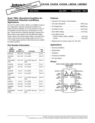
  • 1. NO itle 12 224 324 324 290 bad, Hz, raal plis U C T ME N T RO D E T E P E P L AC E S O L DE D R OB EN OM M Data Sheet RE C CA124, CA224, CA324, LM324, LM2902 May 2001 Quad, 1MHz, Operational Amplifiers for Commercial, Industrial, and Military Applications The CA124, CA224, CA324, LM324, and LM2902 consist of four independent, high-gain operational amplifiers on a single monolithic substrate. An on-chip capacitor in each of the amplifiers provides frequency compensation for unity gain. These devices are designed specially to operate from either single or dual supplies, and the differential voltage range is equal to the power-supply voltage. Low power drain and an input common-mode voltage range from 0V to V+ -1.5V (single-supply operation) make these devices suitable for battery operation. 796.5 Features • Operation from Single or Dual Supplies • Unity-Gain Bandwidth . . . . . . . . . . . . . . . . . . .1MHz (Typ) • DC Voltage Gain . . . . . . . . . . . . . . . . . . . . . . 100dB (Typ) • Input Bias Current . . . . . . . . . . . . . . . . . . . . . . 45nA (Typ) • Input Offset Voltage . . . . . . . . . . . . . . . . . . . . . 2mV (Typ) • Input Offset Current - CA224, CA324, LM324, LM2902 . . . . . . . . . . 5nA (Typ) - CA124. . . . . . . . . . . . . . . . . . . . . . . . . . . . . . . 3nA (Typ) • Replacement for Industry Types 124, 224, 324 Applications Part Number Information PART NUMBER (BRAND) File Number • Summing Amplifiers TEMP. RANGE (oC) PACKAGE PKG. NO. CA0124E -55 to 125 14 Ld PDIP E14.3 CA0124M (124) -55 to 125 14 Ld SOIC M14.15 CA0124M96 (124) -55 to 125 14 Ld SOIC Tape and Reel M14.15 • Multivibrators • Oscillators • Transducer Amplifiers • DC Gain Blocks Pinout CA124, CA224, CA324, LM2902 (PDIP, SOIC) LM324 (PDIP) TOP VIEW CA0224E s) tho CA0224M (224) -40 to 85 14 Ld SOIC M14.15 CA0324E 0 to 70 14 Ld PDIP E14.3 OUTPUT 1 1 CA0324M (324) 0 to 70 14 Ld SOIC M14.15 NEG. INPUT 1 2 CA0324M96 (324) 0 to 70 14 Ld SOIC Tape and Reel M14.15 POS. INPUT 1 3 12 POS. INPUT 4 0 to 70 14 Ld PDIP E14.3 V+ 4 11 V- LM2902N -40 to 85 14 Ld PDIP E14.3 POS. INPUT 2 5 10 POS. INPUT 3 LM2902M (2902) -40 to 85 14 Ld SOIC M14.15 NEG. INPUT 2 6 9 NEG. INPUT 3 LM2902M96 (2902) -40 to 85 14 Ld SOIC Tape and Reel M14.15 OUTPUT 2 7 8 OUTPUT 3 14 OUTPUT 4 2 + 4 + 1 + li- E14.3 + i- 14 Ld PDIP LM324N , usl, -40 to 85 3 13 NEG. INPUT 4 yds er- 1 CAUTION: These devices are sensitive to electrostatic discharge; follow proper IC Handling Procedures. 1-888-INTERSIL or 321-724-7143 | Intersil and Design is a trademark of Intersil Americas Inc. | Copyright © Intersil Americas Inc. 2001
  • 2. CA124, CA224, CA324, LM324, LM2902 Absolute Maximum Ratings Thermal Information Supply Voltage . . . . . . . . . . . . . . . . . . . . . . . . . . . . . . . . 32V or ±16V Differential Input Voltage . . . . . . . . . . . . . . . . . . . . . . . . . . . . . . .32V Input Voltage . . . . . . . . . . . . . . . . . . . . . . . . . . . . . . . . . -0.3V to 32V Input Current (VI < -0.3V, Note 1) . . . . . . . . . . . . . . . . . . . . . . 50mA Output Short Circuit Duration (V+ ≤ 15V, Note 2) . . . . . .Continuous Thermal Resistance (Typical, Note 3) θJA (oC/W) PDIP Package . . . . . . . . . . . . . . . . . . . . . . . . . . . . . 95 SOIC Package . . . . . . . . . . . . . . . . . . . . . . . . . . . . . 175 Maximum Junction Temperature (Die). . . . . . . . . . . . . . . . . . . 175oC Maximum Junction Temperature (Plastic Package). . . . . . . . . 150oC Maximum Storage Temperature Range . . . . . . . . . . -65oC to 150oC Maximum Lead Temperature (Soldering 10s) . . . . . . . . . . . . . 300oC (SOIC - Lead Tips Only) Operating Conditions Temperature Range CA124 . . . . . . . . . . . . . . . . . . . . . . . . . . . . . . . . . -55oC to 125oC CA224, LM2902 . . . . . . . . . . . . . . . . . . . . . . . . . . . -40oC to 85oC CA324, LM324 . . . . . . . . . . . . . . . . . . . . . . . . . . . . . . 0oC to 70oC CAUTION: Stresses above those listed in “Absolute Maximum Ratings” may cause permanent damage to the device. This is a stress only rating and operation of the device at these or any other conditions above those indicated in the operational sections of this specification is not implied. NOTES: 1. This input current will only exist when the voltage at any of the input leads is driven negative. This current is due to the collector base junction of the input p-n-p transistors becoming forward biased and thereby acting as input diode clamps. In addition to this diode action, there is also lateral n-p-n parasitic transistor action on the IC chip. This transistor action can cause the output voltages of the amplifiers to go to the V+ voltage level (or to ground for a large overdrive) for the time duration that an input is driven negative. This transistor action is not destructive and normal output states will reestablish when the input voltage, which was negative, again returns to a value greater than -0.3V. 2. The maximum output current is approximately 40mA independent of the magnitude of V+. Continuous short circuits at V+ > 15V can cause excessive power dissipation and eventual destruction. Short circuits from the output to V+ can cause overheating and eventual destruction of the device. 3. θJA is measured with the component mounted on an evaluation PC board in free air. Electrical Specifications Values Apply for Each Operational Amplifier. Supply Voltage V+ = 5V, V- = 0V, Unless Otherwise Specified TEST CONDITIONS CA124 CA224, CA324, LM324 LM2902 TEMP. (oC) MIN TYP MAX MIN TYP MAX MIN TYP MAX UNITS 25 - 2 5 - 2 7 - - - mV Full - - 7 - - 9 - - 10 mV Full - 7 - - 7 - - 7 - µV/oC Full - - V+ - - V+ - - V+ V V+ = 30V 25 0 - V+ -1.5 0 - V+ -1.5 - - - V V+ = 30V Full 0 - V+ -2 0 - V+ -2 - - - V V+ = 26V Full - - - - - - 0 - V+ -2 V Common Mode Rejection Ratio DC 25 70 85 - 65 70 - - - - dB Power Supply Rejection Ratio DC 25 65 100 - 65 100 - - - - dB Input Bias Current (Note 4) II+ or II- 25 - 45 150 - 45 250 - - - nA II+ or II- Full - - 300 - - 500 - 40 500 nA Input Offset Current II+ - II- 25 - 3 30 - 5 50 - - - nA II+ - II- Full - - 100 - - 150 - 45 200 nA Full - 10 - - 10 - - 10 - pA/oC RL ≥ 2kΩ, V+ = 15V (For Large VO Swing) 25 94 100 - 88 100 - - - - dB RL ≥ 2kΩ, V+ = 15V (For Large VO Swing) Full 88 - - 83 - - 83 - - dB PARAMETER Input Offset Voltage (Note 6) Average Input Offset Voltage Drift RS = 0Ω Differential Input Voltage (Note 5) Input Common Mode Voltage Range (Note 5) Average Input Offset Current Drift Large Signal Voltage Gain 2
  • 3. CA124, CA224, CA324, LM324, LM2902 Electrical Specifications Values Apply for Each Operational Amplifier. Supply Voltage V+ = 5V, V- = 0V, Unless Otherwise Specified (Continued) CA224, CA324, LM324 LM2902 MIN TYP MAX MIN TYP MAX MIN TYP MAX UNITS RL = 2kΩ 25 0 - V+ -1.5 0 - V+ -1.5 - - - V RL = 2kΩ, V+ = 30V Full 26 - - 26 - - - - - V RL = 2kΩ, V+ = 26V Full - - - - - - 22 - - V RL = 10kΩ, V+ = 30V Full 27 28 - 27 28 - 23 28 - V Low Level RL = 10kΩ Full - 5 20 - 5 20 - 5 100 mV Source VI+ = +1V, VI- = 0V, V+ = 15V 25 20 40 - 20 40 - - - - mA VI+ = 1V, VI- = 0, V+ = 15V Full 10 20 - 10 20 - 10 20 - mA VI+ = 0V, VI- = 1V, V+ = 15V 25 10 20 - 10 20 - - - - mA VI+ = 0V, VI- = 1V, VO = 200mV 25 12 50 - 12 50 - - - - µA VI- = 1V, VI+ = 0, V+ = 15V Full 5 8 - 5 8 - 5 8 - mA Crosstalk f = 1 to 20kHz (Input Referred) 25 - -120 - - -120 - - - - dB Total Supply Current RL = ∞ Full - 0.8 2 - 0.8 2 - 0.7 1.2 mA RL = ∞, V+ = 26V Full - - - - - - - 1.5 3 mA Output Voltage Swing High Level Output Current Sink TEST CONDITIONS CA124 TEMP. (oC) PARAMETER NOTES: 4. Due to the PNP input stage the direction of the input current is out of the IC. No loading change exists on the input lines because the current is essentially constant, independent of the state of the output. 5. The input signal voltage and the input common mode voltage should not be allowed to go negative by more than 0.3V. The positive limit of the common mode voltage range is V+ - 1.5V, but either or both inputs can go to +32V without damage. 6. VO = 1.4V, RS = 0Ω with V+ from 5V to 30V, and over the full input common mode voltage range (0V to V+ - 1.5V). Schematic Diagram (One of Four Operational Amplifiers) V+ 4 TO 2, 3, 4 6µA 100 µA 4µA 5 + 6 - 2 Q2 - 2 CCOMP Q3 Q5 Q6 Q4 Q1 7 INPUTS + 3 12 13 Q7 Q10 Q8 VO Q12 50µA TO 2, 3, 4 10 + 9 1 Q13 3 - RSC Q9 V- 11 + 4 Q11 - 3 8 4
  • 4. CA124, CA224, CA324, LM324, LM2902 Typical Performance Curves TA = 25 oC V+ = 30V TA = -40 ≤ TA ≤ 85 oC 120 0.1µF 4 V+ 2 + 100 VI 80 1 500 VO 3 11 V+/2 60 40 V+ = 10 TO 15V V+ = 26V 20 - 2 OUTPUT VOLTAGE (mV) 450 50pF VI 400 1 VO + 3 INPUT 350 OUTPUT 300 0 250 1 10 100 1K 10K 100K FREQUENCY (Hz) 1M 10M 0 FIGURE 1. OPEN LOOP FREQUENCY RESPONSE 1 2 4 5 TIME (µs) 6 7 8 9 FIGURE 2. VOLTAGE FOLLOWER PULSE RESPONSE (SMALL SIGNAL) TA = 25 oC V+ = 15V RL = 2kΩ 4 3 2 1 INPUT VOLTAGE (V) 3 0 4 OUTPUT VOLTAGE (V) OPEN-LOOP VOLTAGE GAIN (dB) 140 3 2 1 0 10 20 30 TIME (µs) 40 FIGURE 3. VOLTAGE FOLLOWER PULSE RESPONSE (LARGE SIGNAL) VICR = 0V V+ 60 V+ = 30V 50 INPUT CURRENT (nA) SUPPLY CURRENT (mA) mA 15V 40 30 5V 20 ID 4 2 4 3 - + 1 11 3 2 TA = 0 oC TO 125 oC 1 10 -55oC 0 -75 -50 -25 0 25 50 75 100 125 TEMPERATURE (oC) FIGURE 4. INPUT CURRENT vs AMBIENT TEMPERATURE 4 0 0 5 10 15 20 25 30 POSITIVE SUPPLY VOLTAGE (V) FIGURE 5. SUPPLY CURRENT vs SUPPLY VOLTAGE
  • 5. CA124, CA224, CA324, LM324, LM2902 Typical Performance Curves (Continued) 20 V+ = 15V 4 +15V 1kΩ 15 OUTPUT SOURCE CURRENT (mA) OUTPUT VOLTAGE SWING (V) 70 100kΩ TA = 25oC 2 +7V 3 - 1 + VI 11 VO 2kΩ 10 5 10K 100K 50 40 30 20 10 0 -75 0 1K 60 1M -50 -25 FREQUENCY (Hz) FIGURE 6. LARGE SIGNAL FREQUENCY RESPONSE 50 75 100 125 TA = 25 oC OPEN LOOP VOLTAGE GAIN (dB) 75 INPUT CURRENT (nA) 25 FIGURE 7. OUTPUT CURRENT vs AMBIENT TEMPERATURE TA = 25oC 50 25 0 0 TEMPERATURE (oC) 10 20 30 POSITIVE SUPPLY VOLTAGE (V) 40 FIGURE 8. INPUT CURRENT vs SUPPLY VOLTAGE 5 150 125 RL = 20kΩ 100 RL = 2kΩ 75 50 25 0 0 10 20 30 40 POSITIVE SUPPLY VOLTAGE (V) FIGURE 9. VOLTAGE GAIN vs SUPPLY VOLTAGE
  • 6. CA124, CA224, CA324, LM324, LM2902 Dual-In-Line Plastic Packages (PDIP) E14.3 (JEDEC MS-001-AA ISSUE D) 14 LEAD DUAL-IN-LINE PLASTIC PACKAGE N E1 INDEX AREA 1 2 3 INCHES N/2 MILLIMETERS SYMBOL D E BASE PLANE -C- A2 SEATING PLANE A e B1 D1 A1 eC B MIN MAX NOTES 0.210 - 5.33 4 A1 0.015 - 0.39 - 4 0.115 0.195 2.93 4.95 - B 0.014 0.022 0.356 0.558 - C L B1 0.045 0.070 1.15 1.77 8 eA L D1 MAX - A2 -A- MIN A -B- C 0.008 0.014 C D 0.735 0.775 18.66 eB 0.204 0.355 19.68 5 1. Controlling Dimensions: INCH. In case of conflict between English and Metric dimensions, the inch dimensions control. 0.005 - 0.13 - 5 0.300 0.325 7.62 8.25 6 E1 NOTES: D1 E 0.010 (0.25) M C A B S 0.240 0.280 6.10 7.11 5 e 0.100 BSC 2. Dimensioning and tolerancing per ANSI Y14.5M-1982. eA eB - L 0.115 4. Dimensions A, A1 and L are measured with the package seated in JEDEC seating plane gauge GS-3. N 5. D, D1, and E1 dimensions do not include mold flash or protrusions. Mold flash or protrusions shall not exceed 0.010 inch (0.25mm). 6. E and eA are measured with the leads constrained to be perpendicular to datum -C- . 7. eB and eC are measured at the lead tips with the leads unconstrained. eC must be zero or greater. 8. B1 maximum dimensions do not include dambar protrusions. Dambar protrusions shall not exceed 0.010 inch (0.25mm). 9. N is the maximum number of terminal positions. 10. Corner leads (1, N, N/2 and N/2 + 1) for E8.3, E16.3, E18.3, E28.3, E42.6 will have a B1 dimension of 0.030 - 0.045 inch (0.76 1.14mm). 6 - 7.62 BSC 0.300 BSC 3. Symbols are defined in the “MO Series Symbol List” in Section 2.2 of Publication No. 95. 2.54 BSC 6 0.430 0.150 14 - 10.92 2.93 3.81 14 7 4 9 Rev. 0 12/93
  • 7. CA124, CA224, CA324, LM324, LM2902 Small Outline Plastic Packages (SOIC) M14.15 (JEDEC MS-012-AB ISSUE C) 14 LEAD NARROW BODY SMALL OUTLINE PLASTIC PACKAGE N INDEX AREA 0.25(0.010) M H B M E INCHES -B- 1 2 MILLIMETERS SYMBOL 3 L MIN MAX MIN MAX NOTES A 0.0532 0.0688 1.35 1.75 - A1 e α µ 9 0.0075 0.0098 0.19 0.25 - 0.3367 0.3444 8.55 8.75 3 0.1497 0.1574 3.80 4.00 4 0.050 BSC 1.27 BSC - B S H 0.2284 0.2440 5.80 6.20 - h 0.0099 0.0196 0.25 0.50 5 L C 0.10(0.004) C A M - 0.51 e A1 B 0.25(0.010) M 0.25 0.33 E -C- 0.10 0.020 C h x 45o A D 0.0098 0.013 D -A- 0.0040 B SEATING PLANE 0.016 0.050 0.40 N NOTES: 1. Symbols are defined in the “MO Series Symbol List” in Section 2.2 of Publication Number 95. α 14 0o 1.27 6 14 8o 0o 7 8o Rev. 0 12/93 2. Dimensioning and tolerancing per ANSI Y14.5M-1982. 3. Dimension “D” does not include mold flash, protrusions or gate burrs. Mold flash, protrusion and gate burrs shall not exceed 0.15mm (0.006 inch) per side. 4. Dimension “E” does not include interlead flash or protrusions. Interlead flash and protrusions shall not exceed 0.25mm (0.010 inch) per side. 5. The chamfer on the body is optional. If it is not present, a visual index feature must be located within the crosshatched area. 6. “L” is the length of terminal for soldering to a substrate. 7. “N” is the number of terminal positions. 8. Terminal numbers are shown for reference only. 9. The lead width “B”, as measured 0.36mm (0.014 inch) or greater above the seating plane, shall not exceed a maximum value of 0.61mm (0.024 inch). 10. Controlling dimension: MILLIMETER. Converted inch dimensions are not necessarily exact. All Intersil products are manufactured, assembled and tested utilizing ISO9000 quality systems. Intersil Corporation’s quality certifications can be viewed at website www.intersil.com/design/quality/iso.asp. Intersil products are sold by description only. Intersil Corporation reserves the right to make changes in circuit design and/or specifications at any time without notice. Accordingly, the reader is cautioned to verify that data sheets are current before placing orders. Information furnished by Intersil is believed to be accurate and reliable. However, no responsibility is assumed by Intersil or its subsidiaries for its use; nor for any infringements of patents or other rights of third parties which may result from its use. No license is granted by implication or otherwise under any patent or patent rights of Intersil or its subsidiaries. For information regarding Intersil Corporation and its products, see web site www.intersil.com Sales Office Headquarters EUROPE Intersil SA Mercure Center 100, Rue de la Fusee 1130 Brussels, Belgium TEL: (32) 2.724.2111 FAX: (32) 2.724.22.05 NORTH AMERICA Intersil Corporation 2401 Palm Bay Rd. Palm Bay, FL 32905 TEL: (321) 724-7000 FAX: (321) 724-7240 7 ASIA Intersil Ltd. 8F-2, 96, Sec. 1, Chien-kuo North, Taipei, Taiwan 104 Republic of China TEL: 886-2-2515-8508 FAX: 886-2-2515-8369
  • 8. This datasheet has been downloaded from: www.DatasheetCatalog.com Datasheets for electronic components.