

Recomendados
Mais conteúdo relacionado
Semelhante a Sniper Rifle Telescope Guide
Semelhante a Sniper Rifle Telescope Guide (20)
Último
Último (20)
Sniper Rifle Telescope Guide
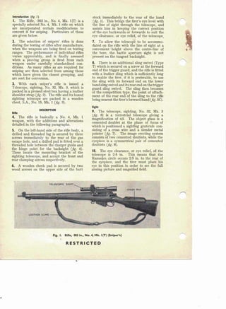
- 1. Introduction (frg. I) I. The Rifle, ·303 in., No.4, Mk. l(T) is a specially selected No.4, Mk. 1 rifle on which are incorporated certain modifications to convert it for sniping. Particulars of these are given below. 2. The selection of snipers' rifles is done during the testing of rifles after manufacture, when the weapons are being fired on testing ranges. The performance of individual rifles varies appreciably, and is finally assessed when a proving group is fired from each weapon under carefully standardised con- ditions. As many rifles. as are required for sniping are then selected from among those which have given the closest grouping, and are sent for conversion. 3. With 'each sniper's rifle is issued a Telescope, sighting, No. 32, Mk. 3, which is packed in a pressed steel box having a leather shoulder strap (jig. 2). The rifle and its boxed sighting telescope are packed in a wooden chest, S.A., No. 15, Mk. 1 (jig. 3). DESCRIPTION Rifle 4. The rifle is basically a No.4, Mk. 1 weapon, with the additions and alterations . detailed in th~ following paragraphs. 5. On the left-hand side of the rifle body, a drilled and threaded lug is secured by three screws immediately to the rear of the. gas escape hole, and a drilled pad is fitted over a threaded hole between the charger guide and the hinge point for the backsight (jig. 4). These locate the mounting' bracket of the sighting telescope, and accept the front and rear clamping screws respectively. 6. A wooden cheek pad is secured by two wood screws on the upper side of the butt stock immediately to the rear of the hand (jig. 1). This brings the firer's eye level with the line of sight through the telescope, and assists him in keeping the correct position of the eye backwards or forwards to suit the eye clearance, or eye relief, of the telescope. 7. To allow the telescope to be accommo- dated on the rifle with the line of sight at a convenient height above the centre-line of the bore, the battle aperture sight is not 'present on the tangent backsight. 8. There is an additiona:l sling swivel (Type T) which is secured on a screw at the forward end of the trigger guard, and the rifle is fitted with a leather sling which is sufficiently long to enable the firer, if it is preferable, to use the sling with its forward end on the lower band sling swivel and its rear end on the trigger guard sling swivel. The sling then becomes of the competition type, the point of attach- ment of the rear end of the sling to the rifle being nearest the firer's forward hand (jig. sq. Sight 9. The telescope, sighting, No. 32, Mk. 3 (jig. 6) is a terrestrial telescope giving a magnification of x3. The object glass is a cemented doublet at the plane of focus of which is positioned a sighting graticule con- sisting of a cross wire and a slender metal pointer (jig. 7). The image erecting system consists Qftwo cemented doublets, while the eyepiece is a symmetrical pair of cemented doublets (jig. 8). 10. The eye clearance, or eye relief, of the telescope is 2·5 in. This means that the Ramsden circle occurs 2·5 in. to the rear of the eyepiece, and the firer must plaee his eye in this position in order to see the full aiming picture and magnified field. ,Fig. I. Rifle, ·303 ln., No.4, Mk. I(T) (Sniper's) RESTRICTED
- 2. Th,s leaf issued with A.L. No. 32, September, 1952 A.P.I64IP, Vol. I, Sect. I, Chap. 13 II. Light transmission of a high order is obtained through the fact that all air-glass surfaces are bloomed, including the exterior surfaces of the object glass and the eyepiece. 12. The telescope is waterproofed; that is, it is tested under compressed air and sealed in manufacture against the admission of the outer atmosphere, This prevents the conden- Fig. 2. Telescope, sighting, No. 32, Mk. 3 RESTRICTED
- 3. Fig. 3. Packing of rifle and sight sation of moisture on the internal air-glass surfaces of the lenses, but does not meanthat the sight can be exposed to rain or heavy mist without deterioration. Leading particulars 13. The leading particulars of the sight are as follows:- Magnification Field of view Working diameter of objective Entrance pupil diameter Exit pupil diameter Eye clearance Collimation x3 8·5 deg, 0·75 in. 0·75 in. 0·25 in. 2·5 in. Adjustedto individual rifle Moving wire, non- illuminated 2·57 in. Graticule Focal length of O.G. Identif!cati on 14. The main nomenclature of the telescope is engraved on the upper side of the telescope tube. Below this, appear the manu- facturing data, thus:- OS.2039A (Optical Store part number) CTS (Manu- turer's monogram or initials) No. 19459 (Manu- turing serial number) " 1S. Each sight is collimated to its companion rifle, 'and must not be used with any other weapon. For this reason, the serial number of the rifle is stamped on the left-hand side of the sight mounting bracket. Fig. 4. Attachment points for sight RESTRICTED
- 4. This leof issued with A.t. No. 32, September, 1952 A.P.I64IP, Vol. I, Sect. I, Chop. 13 Fig. S. Adjustments t9 sling 16. To enable the clamping pieces to remain paired with their cradle portions of the mounting, each is stamped with its identity, and the same marking appears-on the mating cradle piece, on the right-hand side. This marking usually consists of a three-digit number. lens surfaces are bloomed. If, for any reason the blooming is removed, the letter B is erased. 18. Also on the sight tube is the letter W in red oil paint, t in. high. This is put on the sight at the successfulconclusionof its water- proofing test. If any sight fails to pass this test, the letter W does not appear. If the sight is satisfactory in all other respects, it 17. The letter B appears on the sight tube in blue oil paint, i in. high, to denote that the RESTRICTED
- 5. Fig. 6. Components of sight may be issued for use in temperate climates. Waterproofed sights may be used in tropical climates without the risk of condensation on the internal air-glass surfaces of the lenses. numbered intervals of 100 yards and un- numbered intermediate markings of 50 yards. 20. The deflection drum, which is on the left-hand side of the graticule housing, is graduated to left and right of zero up to 16, in numbered intervals of 4 with un-numbered intermediate markings representing 2. These figures denote minutes of angle of deflection, left or right. Range and deflection adjustments 19. The range setting required is obtained by rotation of the range drum situated on the upper side of the graticule housing. The drum is graduated from zero to 1,000 yards with _. -.......___ POINTER '""'-, PLATINOlD SILVER WIRE ·--.........~OOb DIA. I[z-, .~~ . ,~'". ,gg / .~~SSWIRE PLATINOID SILVER.WIRE r 0001 DIA. .>: I . - J~', -If .....x. / CONE·ENDED P,OINTER. i 'ANG~E OF CON'E-(l,OOA""o,, ,/ l --- .....-/ )' DIMENSIONS , __[' ARE IN INCHES "" ., / "---- . ' A. CROSSWIRE DETAIL B. PICTURE PRESENTEDTO FIRER Fig. 7. Sight graticule RESTRICTED ....
- 6. · • I .;. m0 GO 2 F. -- . rJ-~ .;. __. .--' _. .._Q. ~- - .n X0 ~ ..-!-- ~ - ~ :I:.,J Oa- I I Oa- Oa- DIMENSIONS ARE IN INCHES - ":'0 I 11·013 This leaf issued with A.L. No. 32, September, 1952 I 0,," I 1·45 AP.14bl P, Vol. I, Sect. I, Chop. 13 CARE AND CLEANING Fig. 8. Optical system Rifle 21. The screws securing the sight mounting lug and pad on the left-hand side of the body are locked by the centre-punching of metal into one end of the screwdriver slot, and should not work loose. If they do, however, they should be tightened. 22. The rifle should be cleaned and lubri- cated as detailed in Vol. 2, Sect. 1, Chap. 4. Sight Mounting the sight 23. The correct way to mount the sight is to screw up both clamping screws together, and give the final tightening on the rear screw. Weather protection 24. To protect the exterior surfaces of the object glass and the eye-piece from deteriora- tion through the prolonged action of the atmosphere, the leather protector issued with the sight is to be kept in position at all times, except when the telescope is actually in use for sighting or observation. Transportati on 25. Except when the rifle is required for im- mediate use, it must be earned with the sight dismounted and firmly clamped in its box. Lens cleaning 26. Issued with each telescope are two pieces of linen approximately six inches square. These are to be carefully used to clean the exterior surfaces of the object glass and the eyepiece. The linen must be abso- lutely dry. and free from dust or grit; it must be used sparingly, and only the minimum of gentle rubbing must be given to remove smudges or condensation from the lenses. Tightening of screws 27. There are eight screws securing the upper portions of the clamping cradles, four in each. These are locked by the centre- punching of metal into one end of each screwdriver slot; if any of the screws become loose they should be tightened but not other- wise disturbed. . 28. No other screws on the telescope are to be touched, otherwise the optical system may be put out of focus, necessitating a lengthy process of correction on an optical bench. Moreover, the waterproofed condition of the telescope may by broken down by the admission of moist atmosphere into the telescope tube; condensation will then form on the interior surfaces of the lenses, and the sight rendered unserviceable .. P21179 50224/G6087 1O/~2 4000 C & P Gp, 1 RESTRICTED