
Recomendados
Mais conteúdo relacionado
Mais procurados
Mais procurados (20)
Semelhante a Water level indicator alarm
Semelhante a Water level indicator alarm (20)
Mais de Faisal Shahzad Khan
Mais de Faisal Shahzad Khan (9)
Último
Último (20)
Water level indicator alarm
- 2. Digital Logic Design 2 Water Level Indicator Project Proposal by: Faisal Shahzad Khan Submitted to: Sir Tahir Qureshi (DLD Lab)
- 3. Digital Logic Design 3 Overview: Water tank overflow is a common problem which leads to the wastage of water. Though there are many solutions to it like ball valves which automatically stop the water flow once the tank gets full. But being an electronics enthusiastic wouldn’t you like an electronic solution for it? So here is a simple and handy DIY that will guide you to make a circuit which will detect the water level and will raise an alarm upon getting the water tank full or a preset level. This simple transistor based water level indicator circuit is very useful to indicate the water levels in a tank. Whenever tank gets filled, we get alerts on particular levels. Here we have created 4 levels (low, medium, high and full), we can create alarms for more levels. We have added 3 LEDs to indicate initial three levels (A, B, C), and one Buzzer to indicate FULL level (D). When tanks gets filled completely we get beep sound from Buzzer. Circuit Components: 4 - BC547 transistors 6 - 220 ohm resistors 3 - Colour led 1 – Buzzer 5 - 9v battery + battery clip
- 4. Digital Logic Design 4 Diagram: We can consider this whole circuit as 4 small circuits, each one for indicating/alarming, when a particular level (A,B,C,D) of water have been reached. When water level reaches to point A, circuit with RED LED & transistor Q1 gets completed and RED LED glows. Similarly when water level reaches to point B, circuit with YELLOW LED and transistor Q2 gets completed and Yellow LED glows, same goes with point C. And finally when tank gets full (Point D), circuit with buzzer gets completed and buzzer starts beeping.
- 5. Digital Logic Design 5 Working: Here we are using transistor (of NPN type) as a Switch. Initially there is no voltage applied to the base of the Transistor Q1 and the transistor is in OFF state and no current is flowing through collector and emitter and LED is OFF (See below diagram to understand Transistor Pin structure). When the water level reaches to Point A in the tank, the positive side of the battery gets connected to the base of the Transistor Q1 through the water. So when a positive voltage has been applied to the base of the Transistor Q1, it gets into ON state and current starts flowing from collector to emitter. And RED LED glows. You can see resistors (R1, R2, R3) at the base of each transistor, which is used to limit the maximum Base current. Generally a transistor gets its ON state fully when a voltage of 0.7 V is applied to the base. There are also resistors (R4, R5, R6) with each of the LEDs, to drop the voltage across LEDs, otherwise LED may blow up. Same phenomenon happens when water level reaches to Point B. As soon as water level reaches to Point B, a positive voltage gets applied to the Transistor Q2, it gets ON and current started flowing through YELLOW LED, and LED glows. With same principle, GREEN LED glow when water level reaches to Point C.And finally Buzzer beeps when water level reaches to D.
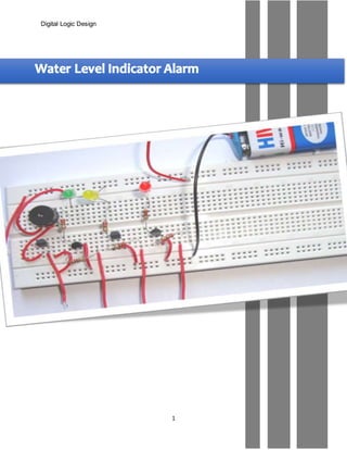
- 6. Digital Logic Design 6 Note that Left most wire in the tank must be lengthier than other four wires in the tanks, because this is the wire which is connected to positive voltage. Figure 1Circuit Diagram on breadboard
- 7. Digital Logic Design 7 CONCLUSION: The water level Indicator employs a simple mechanism to detect and indicate the water level in an overhead tank or any other water container. The sensing is done by using a set of four probes which are placed at four different levels. We can conclude that this system is very beneficial in rural as well as urban areas. It helps in the efficient utilization of available water sources. If used on a large scale, it can provide a major contribution in the conservation of water for us and the future generations. In these days, when the Earth's reserve of consumable water is decreasing every moment, every drop has its value. Water level controller is a simple yet effective way to prevent wastage of water. Its simplicity in design and low cost components make it an ideal piece of technology for the common man. Future Work: In future, we want upgrade this circuit with some sensor which can automatically stop the power supply of the driving pump or motor. As a result the future circuit is not very cheaper the the present one, but we try our best to • Make it simple, • Easy to use, • Easy to install, • To make Available for all, • Try to smaller than the present one. As a result it can available **************