SlideShare uma empresa Scribd logo
1 de 28
Baixar para ler offline
Technical Information
Soliwave M FQR50 / FDR50
Microwave barrier
Advantages at a glance
•	Option of flush front, contact free assembly
•	Mechanically robust
	 - no wear and tear
	 - long serviceable life
	 - maintenance free
•	Indication of the signal strength on the receiver
•	Adjustable sensitivity
•	Easy assembly using R 1½ - or 1½ NPT - thread
•	Conforms to ATEX II 1/2 D, ATEX II 1/2 G and
	 IECEx Zone 0/1
TI00378F/97/EN/13.11
Area of application
The microwave barrier uses a contact free procedure for
detection. It can be installed in containers, conduits, shafts
or on free fall shafts. It is possible to take a measurement
through non-metallic container materials from the outside.
Suitable as level limit switch for controlling and counting all
types of bulk solids.
Typical bulk solids are:
•	wood chips, wood dust or flour
•	plaster, cement, ash
•	paper or cardboard shred
•	gravel, sand
•	dried powders in general
•	bags, boxes
2
Soliwave M FQR50 / FDR50
Endress+Hauser
Table of contents
Function and system design ........................................ 3
Measuring principle ...................................................................... 3
Measuring system ......................................................................... 3
Equipment combinations ............................................................... 3
Input ........................................................................... 4
Measuring range (range of detection) ............................................. 4
Operating frequency ...................................................................... 4
Transmitter power ......................................................................... 4
Output ........................................................................ 4
Output signal ................................................................................ 4
Switching frequency FDR50 .......................................................... 4
Power supply .............................................................. 5
Electrical connection ..................................................................... 5
Ring wiring ................................................................................... 5
Star wiring .................................................................................... 5
Cable entry ................................................................................... 5
Cable gland ................................................................................... 6
Wire specification .......................................................................... 6
Operating conditions .................................................. 7
Installation instructions ................................................................. 7
Notes to orientation ...................................................................... 7
Minimum distance from emitter to receiver ................................... 7
Installation using reflectors ............................................................ 7
Parallel operation .......................................................................... 8
Relation between detection and
minimum distance ........................................................................ 9
Direct installation with threaded connection ................................ 10
Bracket installation in front of microwave-permeable window ...... 11
Bracket installation in front of microwave-permeable window
with danger of condensation on the container's inner wall ........... 11
Bracket installation in front of microwave-permeable sight
glass fitting .................................................................................. 11
Angle installation on container .................................................... 12
Flange mounting using screw-in flange ........................................ 12
Flange mounting using screw-in flange for oblique conical
containers ................................................................................... 12
Flange mounting using screw-in flange with danger of build-up ... 13
Installation with pipe as wave guide ............................................ 13
High-temperature application ...................................................... 14
Environment ............................................................. 15
Ambient temperature .................................................................. 15
Storage temperature .................................................................... 15
Degree of protection .................................................................... 15
Electromagnetic compatibility (EMC) .......................................... 15
Process ...................................................................... 15
Process temperature range ........................................................... 15
Process pressure .......................................................................... 15
Mechanical construction ........................................... 16
Design, dimensions F18-housing (aluminium) .............................. 16
Weight ........................................................................................ 16
Materials ..................................................................................... 16
Process connection ...................................................................... 16
Design, dimensions (stainless steel housing) ................................. 17
Weight ........................................................................................ 17
Material ...................................................................................... 17
Process connection ...................................................................... 17
Human interface ....................................................... 18
Display and operating elements (Receiver) ................................... 18
Calibration with covered path (switching point reached) .............. 19
Calibration with free path (switching point not reached) .............. 19
Configuration of the hysteresis ..................................................... 19
Calibration in applications with very low attenuation ................... 19
Display and operating elements (emitter) ..................................... 19
Certificates and approvals ......................................... 20
CE approval ................................................................................ 20
Ex approval ................................................................................. 20
Radio certification ....................................................................... 20
Other standards and guidelines .................................................... 20
Ordering information ................................................ 21
Ordering information Receiver FDR50 / Emitter FQR50 .............. 21
Comments regarding the product structure .................................. 21
Safety instructions ..................................................... 22
Zone classification ....................................................................... 22
General safety instructions for electrical equipment for
hazardous areas .......................................................................... 22
Specific safety instructions ........................................................... 22
Accessories ............................................................... 23
Mounting bracket ....................................................................... 23
Adapter flange ............................................................................. 23
Installation flanges, material: 316Ti (stainless steel) ...................... 24
Sight glass fitting ......................................................................... 25
HT adapter and extension ........................................................... 27
Documentation ......................................................... 27
Operating instructions (KA) ......................................................... 27
Technical informations ................................................................ 27
Safety instructions ....................................................................... 27
Soliwave M FQR50 / FDR50
Endress+Hauser 3
Function and system design
Measuring principle The FQR50 emitter puts out the microwave signal via an integrated horn antenna. The FDR50 receiver
directly opposite detects this signal and forwards a switching signal to the FTR325 evaluator.
Alarm and control devices may be connected to these relay outputs.
The range of the path is influenced by the different types of materials. The absorption of the microwaves here
depends on the electric characteristics of the attenuating material. Materials with the capacity to conduct
electricity, for example metals, reflect the waves and other materials with lower conductivity only weaken
them or are even penetrated. The attenuation of the microwaves is reduced as the dielectric constant of the
material to be emitted through becomes lower.
FTR325
ReceiverEmitter
Nivotester FTR325
Measuring system The complete measuring system for limit detection consists of:
•	an emitter FQR50,
•	a receiver FDR50 and
•	an evaluator Nivotester FTR325
Optical or acoustic signallers, contactors, relays, solenoids etc. may be connected to the Nivotester.
Equipment combinations The emitter and receiver unit FQR50/FDR50-C* (ATEX II 1/2G Ex ia IIC T4 and ATEX II 1/2D Ex iaD
20/21 IP66 T98°C resp.) may only be combined with the Nivotester FTR325-B* (ATEX II (1)G [Ex ia] IIC
and ATEX II (1)D [Ex iaD] resp.).
The emitter and receiver unit FQR50/FDR50-D* (IECEx Zone 0/1 Ex ia IIC T4 and IECEx Ex iaD 20/21
IP66 T98°C resp.) may only be combined with the Nivotester FTR325-D* (IECEx [Zone 0] [Ex ia] IIC and
IECEx [Ex iaD] resp.).
Note:
The devices FQR50/FDR50-A* (non hazardous area) and FQR50/FDR50-B* (ATEX II 1/2D IP66 T102°C)
of the microwave barrier Soliwave M are no longer available, they have been replaced by the Soliwave
FQR56/FDR56-AA* (non hazardous area) and FQR56/FDR56-BA* (ATEX II 1/2D Ex ta/tb IIIC T102°C
Da/Db IP66). Please refer to the Technical Information TI00443F/97/EN for details about the new micro-
wave barrier Soliwave.
The following equipment combinations are impossible:
•	FQR50/FDR50-C* (ATEX II 1/2G Ex ia IIC T4 and ATEX II 1/2D Ex iaD 20/21 IP66 T98°C resp.) with
	 Nivotester FTR325-A* (non hazardous area)
•	FQR50/FDR50-C* (ATEX II 1/2G Ex ia IIC T4 and ATEX II 1/2D Ex iaD 20/21 IP66 T98°C resp.) with
	 Nivotester FTR325-D* (IECEx [Zone 0] [Ex ia] IIC and IECEx [Ex iaD] resp.)
•	FQR50/FDR50-D* (IECEx Zone 0/1 Ex ia IIC T4 and IECEx Ex iaD 20/21 IP66 T98°C resp.) with
	 Nivotester FTR325-A* (non hazardous area)
•	FQR50/FDR50-D* (IECEx Zone 0/1 Ex ia IIC T4 and IECEx Ex iaD 20/21 IP66 T98°C resp.) with
	 Nivotester FTR325-B* (ATEX II (1)G [Ex ia] IIC and ATEX II (1)D [Ex iaD] resp.)
4
Soliwave M FQR50 / FDR50
Endress+Hauser
Input
Measured variable Absorption of the electromagnetic waves produced by the FQR50 emitter.
Measuring range
(range of detection)
When there is an unrestricted path between the emitter and the receiver the maximum range, depending on
the version (see ordering information), is 8 m or 20 m.
The range is also dependent on the container walls to be penetrated.
Operating frequency 24.125 GHz
Transmitter power The maximum power produced by the FQR50 emitter is 100 mW e.i.r.p.
(equivalent isotrope radiation performance).
•	Power density directly in front of the emitter:	 1 mW / cm2
•	Power density at a distance of 1 m:	 0.3 µW / cm2
Note:
The power density is significantly below the recommended limit values of the ICNIRP guidelines
"Guidelines for Limiting Exposure to Time-Varying Electric, Magnetic, and Electromagnetic Fields (up to
300 GHz)" and is thus harmless for humans!
Output
Output signal Switching signal for the Nivotester FTR325
Switching frequency FDR50 max. 2 Hz
Soliwave M FQR50 / FDR50
Endress+Hauser 5
Power supply
Electrical connection A suitable wire (see "Wire specification") is used to connect the emitter and receiver of the Soliwave M
microwave barrier with the Nivotester FTR325. The following wiring variants are permitted:
Ring wiring
6 7 8 6 7 8
1 2 1516 3 4 5
1 1 22 3 31 2 3
Emitter FQR50 Receiver FDR50
Contact circuit (terminal 3, 4, 5) and
alarm output (terminal 15, 16) resp.:
U	=	 max. 253 V (AC) / 40 V (DC)
I	 =	 max. 2 A
P	 =	 max. 500 VA (cos φ ≥ 0.7) / 80 W
Power supply (terminal 1, 2):
A	 =	 85 - 253 V (AC), 50/60 Hz
E	 =	 20 - 60 V (DC)
		 20 - 30 V (AC), 50/60 Hz
FTR325
Star wiring
6 7 8 6 7 8
1 2 1516 3 4 5
1 1 22 3 31 2 3
Emitter FQR50 Receiver FDR50
Contact circuit (terminal 3, 4, 5) and
alarm output (terminal 15, 16) resp.:
U	=	 max. 253 V (AC) / 40 V (DC)
I	 =	 max. 2 A
P	 =	 max. 500 VA (cos φ ≥ 0.7) / 80 W
Power supply (terminal 1, 2):
A	 =	 85 - 253 V (AC), 50/60 Hz
E	 =	 20 - 60 V (DC)
		 20 - 30 V (AC), 50/60 Hz
FTR325
Cable entry •	 M20 x 1.5 or
•	 ½ NPT
6
Soliwave M FQR50 / FDR50
Endress+Hauser
Cable gland •	 M20 x 1.5:
	 - Degree of protection IP66
	 - Scope of supply: 2
Wire specification •	 Usual commercial installation wire
•	 Conductor cross-section: max. 1.5 mm
•	 Resistance: 15 Ω/km ≤ R' ≤ 150 Ω/km
•	 Inductance: 0.4 mH/km ≤ L' ≤ 1 mH/km
•	 Capacitance: 45 nF/km ≤ C' ≤ 200 nF/km
•	 Length of spurs max. 1000 m (IIC) and 5000 m (IIB) respectively
Example cable length
Copper cable, specific resistance ρ = 0.0172 Ωmm2
/m, cross section 0.75mm2
It applies: R [Ω] = (ρ [Ωmm2
/m] * l [m]) / A [mm2
]
The maximum cable length is 1090 m.
Soliwave M FQR50 / FDR50
Endress+Hauser 7
Operating conditions
Installation instructions Both the FQR50 emitter and the FDR50 receiver are equipped with a standard thread (R 1½ in compliance
with EN10226 and 1½" NPT in complience with ANSI/ASME B1.20.1) as a process connector. This makes a
simple installation in the existing container sleeves or fittings possible.
Note:
•	The fronts of the emitter and the receiver should face each other and be concentric.
•	Since the microwaves are polarised the FQR50 emitter and the FDR50 receiver may not be rotated around
	 their longitudinal axis, unless they are rotated exactly 180°.
•	Disturbing reflections at metal parts are to be avoided.
•	An improvement in the signal quality can be achieved by an adjustable mounting of emitter and receiver
	 of ± 15 mm along their longitudinal axis (see "Angle installation" on page 12).
Notes to orientation
Minimum distance from
emitter to receiver
A minimum distance of 30 mm should be maintained between the emitter and the receiver.
Installation using reflectors If, for construction reasons, a direct confrontation of the FQR50 emitter and the FDR50 receiver is not pos-
sible, the microwave beam can be redirected via a flat metal mirror (reflectors). By using reflectors the range
of the microwave barrier is reduced by approximately 10% per reflector.
8
Soliwave M FQR50 / FDR50
Endress+Hauser
ReflectorReflector
Reflector
Please make sure that FQR50 emitter and FDR50 receiver are placed at symmetrical angles toward the
reflector (entry angle = exit angle), since otherwise the receiver will get no evaluable signal.
Reflector
Parallel operation It may be necessary to utilize several microwave barriers (each consisting of a FQR50 emitter, a FDR50
receiver and a FTR325 Nivotester) in one place (for example for detecting several limit states in a pipeline,
see figure). To prevent interferences between the microwave paths, various modulation frequencies can be
adjusted on the FQR50 emitter (as of production date July 2008).
1 2 3
3 2 1
Switch setting S1 Modulation frequency
1
(factory setting)
2
3
Soliwave M FQR50 / FDR50
Endress+Hauser 9
The switch setting of S1 has no effect when using a single microwave barrier and can be any way. Regard the
following advice for parallel use of several microwave barriers:
-	 Use the differnt modulation frequencies in sequence, e.g. 1, 2, 3, 1, ...
-	 Regard the minimum distance A depending on the detection distance D.
-	 Rotate every other microwave barrier by 90° to eliminate interferences (see figure, pertains to emitter and
	 receiver).
A
D
Relation between
detection and
minimum distance
The following relation between detection distance D and minimum distance between microwave barriers A
applies to parallel operation of several barriers using emitters with selectable modulation frequency as shown
in the figure.
10
20
30
40
50
60
70
80
90
100
110
120
130
140
150
160
170
180
190
200
210
45
40
35
30
25
20
15
10
5
0
A [cm]
D
[cm]
Note:
The values given in the diagramm relate to optimum installation conditions and may vary depending on the
actual installation situation. The spacing of the microwave barriers may have to be adjusted with installations
in sealed metal containers, funnels, or similar, due to occuring reflections for example.
10
Soliwave M FQR50 / FDR50
Endress+Hauser
Installation examples Example 1: Bulk counting
FTR325
Bulk good
Emitter Receiver
Evaluator
FTR325
Example 2: Limit detection of bulk solids
FTR325
Product
Emitter Receiver
Evaluator
FTR325
Direct installation with
threaded connection R 1½ /
1½ NPT
Soliwave M FQR50 / FDR50
Endress+Hauser 11
Bracket installation in
front of microwave-
permeable window Mounting bracket *1
Bracket installation in front
of microwave-permeable
window with danger
of condensation on the
container's inner wall
Bracket installation in
front of microwave-
permeable sight glass
fitting
Mounting bracket *1
Sight glass fitting *2
Mounting bracket *1
Sight glass fitting *2
A*3
Purge air *6
12
Soliwave M FQR50 / FDR50
Endress+Hauser
Angle installation on
container
Mounting bracket *1
Securing arm
max.
200 *4
Installation flange
Ceramic disc (aluminium oxide)
*1	 Suitable installation brackets are available as accessories, see "Accessories"
*2	 Suitable microwave-permeable sight glass fittings are available as accessories, see "Accessories"
*3	The distance A depends on the nominal diameter of the sight glass fitting (or the diameter of the sight
glass) and the temperature at the fitting. To prevent possible signal attenuation, we recommend keeping
the distance as short as possible (e. g. max. 40 mm at DN50).
*4	Distance for temperature reduction between the process temperature and max. 70°C at the microwave
barrier
*5	 Various installation adapters (e. g. for angle installation) are available as special equipment packages.
*6	We recommend using purge air to prevent fouling (material accumulation) in the nozzle that is open to
the process. Alternatively, you can also close the nozzle using a plastic plug.
Flange mounting using
screw-in flange L
Plastic plug
Installation flange *1
Note:
•	The maximum length L depends on the dielectric constant and the water absorption of the plastic materi-
al. Observe the manufacturer's specifications.
•	We recommend PTFE as the material, as this allows the length at the emitter and receiver to be
up to 300 mm.
•	For optimal orientation, the emitter and receiver should be able to be moved by ± 10 mm along their
longitudinal axis.
Flange mounting using
screw-in flange for oblique
conical containers
Soliwave M FQR50 / FDR50
Endress+Hauser 13
Flange mounting using
screw-in flange with
danger of build-up
Installation with pipe as
wave guide
L
Note:
•	This type of mounting is recommended if conditions at the process or in the area surrounding the process
are unfavorable (such as high temperatures or heavy contamination) or if the building's situation does not
permit direct installation.
•	The pipe can be made of any desired metallic material, and the length L is unimportant due to the wave-
guide effect.
•	Edges inside the pipe (for example at transitions) can cause signal attenuation and thus should be avoided
wherever possible.
14
Soliwave M FQR50 / FDR50
Endress+Hauser
High-temperature
application
For applications with process temperatures up to +450°C, the temperature reduction to max. +70°C takes
place on the microwave barrier with a corresponding high-temperature adapter (with extension where
necessary). The length of the adapter is based on the insulation thickness to be penetrated (if present) and
the ambient conditions at the measuring point.
Tmax = +70°CTP,max = +450°C
Pmax = 80 ... 510 kPa abs.
(0,8 ... 5,1 bar abs.)
Wall Insulation
HT adapter
Extension
X
Note:
•	To maintain the maximum temperature of +70°C at the FQR50/FDR50, we recommend a minimum
difference (X) of 200 mm between the process or the insulation and the devices.
•	 The individual extensions can also be combined in any way desired.
•	 We recommend the use of variants with a measuring range of max. 20 m, because each high-
	 temperature adapter results in a reduction of the range.
Soliwave M FQR50 / FDR50
Endress+Hauser 15
Environment
Ambient temperature •	 -20°C ... +70°C
Storage temperature •	 -40°C ... +80°C
Degree of protection •	 With closed housing: IP 66
•	 With open housing: IP 20
Electromagnetic
compatibility (EMC)
•	 Interference Emission to EN 61326, Electrical Equipment Class B
•	 Interference Immunity to EN 61326, Appendix A (Industrial)
Process
Process temperature range •	 -40°C to +70°C (without optional adapter for temperature reduction)
•	 -40°C to +450°C (with optional adapter for temperature reduction, see Accessories)
Process pressure •	 80 to 480 kPa absolute (0.8 to 4.8 bar absolute)
	 (Applies only when FQR50 emitter or FDR50 receiver is installed directly in the process.)
•	80 to 510 kPa absolute (0.8 to 5.1 bar absolute)
(Applies only when using the optional adapter for temperature reduction.)
16
Soliwave M FQR50 / FDR50
Endress+Hauser
Mechanical construction
Design, dimensions F18-
housing (aluminium)
Weight •	 1.0 kg
Materials •	 Housing: Aluminium
•	 Process connection (fluid-wetted parts):
	 - Stainless steel 316Ti/1.4571
	 - Sensor diaphragm: PTFE
•	 Cable glands: PA
Process connection •	 Thread R 1½ (EN 10226) or
•	 1½ NPT (ANSI/ASME B1.20.1)
Soliwave M FQR50 / FDR50
Endress+Hauser 17
Design, dimensions
(stainless steel housing)
Weight •	 2.1 kg
Material •	 Housing: Stainless steel 316TI/1.4571
•	 Process connection (fluid-wetted parts):
	 - Stainless steel 316Ti/1.4571
	 - Sensor diaphragm: PTFE
•	 Cable glands: PA
Process connection •	 Thread R 1½ (EN 10226) or
•	 1½ NPT (ANSI/ASME B1.20.1)
18
Soliwave M FQR50 / FDR50
Endress+Hauser
Human interface
By using frequencies in the 24 GHz range it is possible to detect products having low attenuation even with
low amounts of bulk product between the emitter and the receiver. The calibration options of the units offer
the necessary flexibility to be able to adjust the barrier to individual situations easily.
•	Rough/fine calibration (r, n)
•	Hysteresis p selected in 2 stages
•	LED field strength is displayed as an adjustment and positioning aid
•	LED for the switching output m and for operation status q (supply voltage is present)
Display and operating
elements (Receiver)
1 2 3 4
Bar
Dot
1 2 3 4 1 2 3 4 1 2 3 4 1 2 3 4
Sensitivity
minimum
Sensitiivity
maximum
* factory setting
*
m
r
q
p
o
n
The microwave barrier Soliwave M is calibrated using 4 DIP switches for rough calibration r and a potenti-
ometer for fine calibration n on the attenuation necessary for unambiguous product recognition. When there
is sufficient attenuation or when the microwaves are interrupted by the product, the receiver reacts with an
output (LED m) on the through connection to the external evaluator FTR325. Field status and operation
status are indicated on the spot either by a bar graph or by a dot display o (switchable by p).
•	High sensitivity can be set for the detection of materials with a very high dielectric constant or of metals
	 because then the beam is attenuated strongly enough or covered.
•	The sensitivity has to be adjusted precisely for the detection of materials with a low dielectric constant.
Soliwave M FQR50 / FDR50
Endress+Hauser 19
Calibration with covered path
(switching point reached)
•	The sensitivity of the microwave receiver FDR50 is to be adjusted in such a way that none, as a maximum
	 however the first two LEDs in the LED line light up. If this should not be the case, the sensitivity is to be
	 reduced appropriately.
•	With the path uncovered, LED 6 must light up in the LED line as a minimum.
Calibration with free path
(switching point not reached)
•	The sensitivity of the receiver FDR50 must be adjusted in such a way that as a maximum LED 10 just
	 starts to light up, but at least LED 6 in the LED line must light up.
•	With the path covered, only LED 3 must light up in the LED line at the most.
•	After a few filling procedures, the sensitivity should be readjusted, if necessary, with the path covered.
Configuration of the
hysteresis
Switch position
large hysteresis
Switch position
small hysteresis
Covered path Uncovered path
Calibration in applications
with very low attenuation
Example: Paper shred
Setting up with covered path
•	Reduce hysteresis:
	 -	 adjust switch
•	Adjust sensitivity:
	 -	 change the rough and fine calibration so that the LEDs 1 to 3 in the LED line light up.
Display and operating
elements (emitter)
1 2 3
3 2 1
m
The emitter FQR50 has a green LED m, that signals the operating status (supply voltage present).
20
Soliwave M FQR50 / FDR50
Endress+Hauser
Certificates and approvals
CE approval The Soliwave M microwave barrier is in conformity with the statutory requirements of the EC Directives.
The manufacturer confirms successful testing of the device by affixing to it the CE mark.
Ex approval ATEX II 1/2D Ex iaD 20/21 IP66 T98°C	 (Certification number: BVS 07 ATEX E 148 X)
ATEX II 1/2G Ex ia IIC T4			 (Certification number: BVS 07 ATEX E 148 X)
IECEx Zone 0/1 Ex ia IIC T4			 (Certification number: IECEx BVS 09.0007X)
IECEx Ex iaD 20/21 IP66 T98°C		 (Certification number: IECEx BVS 09.0007X)
Radio certification RTTE according to EN 300440-2
FCC [FCC ID UAS-FQR50]
Other standards and
guidelines
Directive 1999/05/EC Article 3.1 (a) and 3.1 (b) and the included Directives 73/23/EEC and 89/336/EEC
Soliwave M FQR50 / FDR50
Endress+Hauser 21
Ordering information
Receiver FDR50 /
Emitter FQR50
10 Approval:
C ATEX II 1/2G Ex ia IIC T4
ATEX II 1/2D Ex iaD 20/21 IP66 T98°C
D IECEx Zone 0/1 Ex ia IIC T4
IECEx Ex iaD 20/21 IP66 T98°C
Y Special version, to be specified
20 Distance emitter/receiver:
1 Measuring range *1
maximum 8 m
2 Measuring range *1
maximum 20 m
9 Special version, to be specified
30 Process connection and material:
R Thread R 1½ EN10226, stainless steel 316Ti
S Thread 1½ NPT ANSI/ASME, stainless steel 316Ti
Y Special version, to be specified
40 Housing and cable entry:
D Aluminium F18-housing IP66, M20x1.5
F Aluminium F18-housing IP66, ½ NPT
G Stainless steel 316Ti, IP66, M20x1.5
H Stainless steel 316Ti, IP66, ½ NPT
Y Special version, to be specified
50 Optional features:
A Basic equipment
Y Special version, to be specified
FDR50/FDR50 -
*1
Please select the same version for emitter FQR50 and receiver FDR50
Comments regarding
the product structure
Only the following device combinations are possible:
•	 FQR50/FDR50-C* with FTR325-B*
•	 FQR50/FDR50-D* with FTR325-D*
22
Soliwave M FQR50 / FDR50
Endress+Hauser
Safety instructions
Zone classification
FTR325FTR325
Non hazardous area Hazardous area
FTR325-B*
Emitter
FQR50-C*
Receiver
FDR50-C*
Zone 0 /
Zone 20
Zone 1 /
Zone 21
FTR325-D*
Emitter
FQR50-D*
Receiver
FDR50-D*
Zone 0 /
Zone 20
Zone 1 /
Zone 21
General safety instructions
for electrical equipment for
hazardous areas
•	Install it according to manufacturer's specifications and the standards and regulations applicable in your
	 area.
•	Installation, electrical connection, commissioning, operation and, if necessary, maintenance may be carried
out only by trained specialists authorized to do so by the facility's owner-operator.
•	Do not operate the devices of the microwave barrier outside of the electrical, thermal or mechanical cha-
racteristic quantities.
•	Seal unused entry glands with approved sealing plugs that correspond to the type of protection. The plastic
	 transportation plug does not meet this requirement and must therefore be changed during the installation
	 process.
•	For additional safety instructions, refer to the XA00219F (FQR50/FDR50-C*) or XA00484F
(FQR50/FDR50-D*).
Specific safety instructions •	The emitter/receiver unit FQR50/FDR50-C* may only be combined with the Nivotester FTR325-B*.
•	The emitter/receiver unit FQR50/FDR50-D* may only be combined with the Nivotester FTR325-D*.
Soliwave M FQR50 / FDR50
Endress+Hauser 23
Accessories
Mounting bracket The FQR50 emitter and FDR50 receiver can be easily installed on existing frames using a mounting
bracket.
Mounting bracket for frame mounting
•	 Aluminum material:	 Part number 52017501
•	 Plastic material:	 Part number 52017502
M6 / ¼ UNC86
66
66
66
Adapter flange The screw assembly of the microwave barrier Soliwave M is possible by an aluminium adapter flange
(directly compatible to the microwave barrier QR30/DR30) or by a DIN flange.
Adapter flange (directly compatible to the microwave barrier QR30/DR30)
•	DN 40 PN 6, connection dimensions according to DIN EN 1092-1, material aluminium,
	 with Rp 1½ thread: Part number 71006345
•	1½ 150 lbs, connection dimensions according to ANSI/ASME B16.5, material aluminium,
	 with 1½ NPT thread: Part number 71006346
24
Soliwave M FQR50 / FDR50
Endress+Hauser
Installation flanges, material:
316Ti (stainless steel)
Connection dimensions to DIN EN 1092-1, with Rp 1½ internal thread:
•	DN40 PN16				 Part number 71006348
with inspection certificate to EN 10204-3.1		 Part number 71108383
•	DN50 PN16				 Part number 71006350
with inspection certificate to EN 10204-3.1		 Part number 71108388
•	DN100 PN16					 Part number 71006352
with inspection certificate to EN 10204-3.1		 Part number 71108390
d3
Rp1½
d2
d1
D
Flange
d1/
mm
d2/
mm
d3/
mm
D/
mm
Number
of holes
DN40/PN16 110 150 18 16 4
DN50/PN16 125 165 18 18 4
DN100/PN16 180 220 18 20 8
Connection dimensions to ANSI/ASME B16.5, with 1½ NPT internal thread:
•	1½ 150 lbs				 Part number 71006349
with inspection certificate to EN 10204-3.1		 Part number 71108387
•	2 150 lbs				 Part number 71006351
with inspection certificate to EN 10204-3.1		 Part number 71108389
•	4 150 lbs				 Part number 71006353
with inspection certificate to EN 10204-3.1		 Part number 71108391
d3
1½NPT
Flange
d1/
mm
d2/
mm
d3/
mm
D/
mm
Number
of holes
1½ 150 lbs 98.6 127 15.7 17.5 4
2 150 lbs 120.7 152.4 19.1 19.1 4
4 150 lbs 190.5 228.6 19.1 23.9 8
d1
d2
D
Soliwave M FQR50 / FDR50
Endress+Hauser 25
Sight glass fitting Screw-type fitting similar to DIN 11851, materials: stainless steel 304, silicone and C4400,
Pmax = 600 kPa (6 bar), Tmax = 200°C, borosilicate glass, screw-on installation, thread adapter nut
d2
D
A
DN
d1/
mm
d2/
mm
s/
mm
D/
mm
d/
mm
A/
mm
a/
mm
50 50 63 10 92 61 44 21
80 80 94 12 127 93 57 25
100 100 113 15 148 114 69 34
d1
DN
d
sa
•	 DN 50	 Part number 71026440
•	 DN 80	 Part number 71026441
•	 DN 100	 Part number 71026442
Weld-in fitting for unpressurized containers, materials: stainless steel 316Ti and silicone, Tmax = 200°C,
borosilicate glass, screw-on installation
DN
d1/
mm
d2/
mm
D/
mm
k/
mm
d3/
mm
50 80 100 140 120 102
80 100 125 165 145 127
100 125 150 190 170 152
d2
d3
d1
k
D
10
15
•	 DN 50	 Part number 71026443
•	 DN 80	 Part number 71026444
•	 DN 100	 Part number 71026445
26
Soliwave M FQR50 / FDR50
Endress+Hauser
Weld-in fitting to DIN 28120, materials: stainless steel 316Ti/321 and silicone,
Pmax = 1 MPa (10 bar), Tmax = 200°C, borosilicate glass, screw-on installation
k
D
DN
d1/
mm
d2/
mm
D/
mm
k/
mm
h1/
mm
d3/
mm
50 80 100 165 125 16 102
80 100 125 200 160 20 127
100 125 150 220 180 22 152
d1
d2
d3
h130
45°
•	 DN 50	 Part number 71026446
•	 DN 80	 Part number 71026447
•	 DN 100	 Part number 71026448
Flange fitting to DIN 28121 for screwing onto existing counterflanges, materials: stainless steel 316Ti,
PTFE and C4400, Pmax = 2.5 MPa (25 bar), Tmax = 200°C, borosilicate glass
d10
DN
d1/
mm
d3/
mm
s/
mm
D/
mm
k/
mm
h3/
mm
d9/
mm
d10/
mm
50 65 80 15 165 125 41 18 82
80 80 100 20 200 160 50 18 102
100 100 125 25 235 190 59 22 127
h3
7
d3
d1
d9
k
D
d1
d10
Gasket
(product side)
s
•	 DN 50	 Part number 71026449
•	 DN 80	 Part number 71026450
•	 DN 100	 Part number 71026451
Soliwave M FQR50 / FDR50
Endress+Hauser 27
HT adapter and extension
R1½/1½NPT
170 L
m n
HT adapter m with flush-mounted ceramic disk:
•	 Thread R 1½ or Rp 1½, 55mm hex, 316Ti/1.4571
	 Part number 71113441
•	 Thread 1½ NPT, 55mm hex, 316Ti/1.4571
	 Part number 71113449
Extension for HT adapter n:
•	 Thread R 1½ or Rp 1½, 55mm hex, 316Ti/1.4571
	 L = 225 mm	 Part number 71113450
	 L = 325 mm	 Part number 71113451
	 L = 525 mm	 Part number 71113452
•	 Thread 1½ NPT, 55mm hex, 316Ti/1.4571
	 L = 225 mm	 Part number 71113453
	 L = 325 mm	 Part number 71113454
	 L = 525 mm	 Part number 71113455
Documentation
Operating instructions (KA) Soliwave M FQR50/FDR50
KA00206F/97/A6
Nivotester FTR325
KA00205F/97/A6
Technical informations Nivotester FTR325
TI00377F/97/EN
Safety instructions Soliwave M FQR50/FDR50-C* with the Nivotester FTR325-B*
XA00219F/97/A3
Soliwave M FQR50/FDR50-D* with the Nivotester FTR325-D*
XA00484F/97/EN
28
Soliwave M FQR50 / FDR50
Endress+Hauser
Instruments International
Endress+Hauser
Instruments International AG
Kaegenstrasse 2
4153 Reinach
Switzerland
Tel.+41 61 715 81 00
Fax+41 61 715 25 00
www.endress.com
info@ii.endress.com
TI00378F/97/EN/13.11
InDesign 6.0.6
Subject to modification

Mais conteúdo relacionado

Mais procurados

Catalog ELCB Mitsubishi-Beeteco.com
Catalog ELCB Mitsubishi-Beeteco.comCatalog ELCB Mitsubishi-Beeteco.com
Catalog ELCB Mitsubishi-Beeteco.comBeeteco
 
Schnieder mccb li st
Schnieder mccb li stSchnieder mccb li st
Schnieder mccb li stRamesh Meti
 
Turbimax cus52 d endress+hauser datasheet-turbidity sensor
Turbimax cus52 d endress+hauser datasheet-turbidity sensorTurbimax cus52 d endress+hauser datasheet-turbidity sensor
Turbimax cus52 d endress+hauser datasheet-turbidity sensorENVIMART
 
E82 ev _8200 vector 0.25-90kw__v3-0__en
E82 ev _8200 vector 0.25-90kw__v3-0__enE82 ev _8200 vector 0.25-90kw__v3-0__en
E82 ev _8200 vector 0.25-90kw__v3-0__enCharles Santos
 
Dienhathe.com mccb-3 vl
Dienhathe.com mccb-3 vlDienhathe.com mccb-3 vl
Dienhathe.com mccb-3 vlDien Ha The
 
ABB Medium Voltage MV Surge Arresters - AC & DC Surge Arresters & Protection...
ABB Medium Voltage MV Surge Arresters -  AC & DC Surge Arresters & Protection...ABB Medium Voltage MV Surge Arresters -  AC & DC Surge Arresters & Protection...
ABB Medium Voltage MV Surge Arresters - AC & DC Surge Arresters & Protection...Thorne & Derrick International
 
Catalog contactor fuji-electric Mới Nhất - Hạo Phương
Catalog contactor fuji-electric Mới Nhất - Hạo PhươngCatalog contactor fuji-electric Mới Nhất - Hạo Phương
Catalog contactor fuji-electric Mới Nhất - Hạo PhươngCTY TNHH HẠO PHƯƠNG
 
Avtron Encoders Catalog
Avtron Encoders CatalogAvtron Encoders Catalog
Avtron Encoders CatalogJim Milbaugh
 
Catalog ls susol ul_mccb_e_1104_dienhathe.vn
Catalog ls susol ul_mccb_e_1104_dienhathe.vnCatalog ls susol ul_mccb_e_1104_dienhathe.vn
Catalog ls susol ul_mccb_e_1104_dienhathe.vnDien Ha The
 
Utility Tool - LV HV Cable Jointing, Cable Preparation & Overhead Line Toolin...
Utility Tool - LV HV Cable Jointing, Cable Preparation & Overhead Line Toolin...Utility Tool - LV HV Cable Jointing, Cable Preparation & Overhead Line Toolin...
Utility Tool - LV HV Cable Jointing, Cable Preparation & Overhead Line Toolin...Thorne & Derrick International
 
ABB CMF Indoor Fuses IEC Standard 3.6kV-12kV - High Voltage Current Limiting ...
ABB CMF Indoor Fuses IEC Standard 3.6kV-12kV - High Voltage Current Limiting ...ABB CMF Indoor Fuses IEC Standard 3.6kV-12kV - High Voltage Current Limiting ...
ABB CMF Indoor Fuses IEC Standard 3.6kV-12kV - High Voltage Current Limiting ...Thorne & Derrick International
 

Mais procurados (20)

FTW360 compact pump protector
FTW360 compact pump protectorFTW360 compact pump protector
FTW360 compact pump protector
 
Catalog ELCB Mitsubishi-Beeteco.com
Catalog ELCB Mitsubishi-Beeteco.comCatalog ELCB Mitsubishi-Beeteco.com
Catalog ELCB Mitsubishi-Beeteco.com
 
Catalogue mitsubishi thiet bi dien mccb
Catalogue mitsubishi thiet bi dien mccbCatalogue mitsubishi thiet bi dien mccb
Catalogue mitsubishi thiet bi dien mccb
 
Schnieder mccb li st
Schnieder mccb li stSchnieder mccb li st
Schnieder mccb li st
 
MCCB Easy Pact ECLB
MCCB Easy Pact ECLBMCCB Easy Pact ECLB
MCCB Easy Pact ECLB
 
Turbimax cus52 d endress+hauser datasheet-turbidity sensor
Turbimax cus52 d endress+hauser datasheet-turbidity sensorTurbimax cus52 d endress+hauser datasheet-turbidity sensor
Turbimax cus52 d endress+hauser datasheet-turbidity sensor
 
Catalogue siemens MCB6 SX
Catalogue siemens MCB6 SXCatalogue siemens MCB6 SX
Catalogue siemens MCB6 SX
 
Thông số kĩ thuật siemens monitoring devices
Thông số kĩ thuật siemens monitoring devicesThông số kĩ thuật siemens monitoring devices
Thông số kĩ thuật siemens monitoring devices
 
Thông số kĩ thuật siemens miniature circuit breakers
Thông số kĩ thuật siemens miniature circuit breakersThông số kĩ thuật siemens miniature circuit breakers
Thông số kĩ thuật siemens miniature circuit breakers
 
E82 ev _8200 vector 0.25-90kw__v3-0__en
E82 ev _8200 vector 0.25-90kw__v3-0__enE82 ev _8200 vector 0.25-90kw__v3-0__en
E82 ev _8200 vector 0.25-90kw__v3-0__en
 
Ripley Utility Tool Cable Preparation Tools
Ripley Utility Tool Cable Preparation ToolsRipley Utility Tool Cable Preparation Tools
Ripley Utility Tool Cable Preparation Tools
 
Dienhathe.com mccb-3 vl
Dienhathe.com mccb-3 vlDienhathe.com mccb-3 vl
Dienhathe.com mccb-3 vl
 
ABB Medium Voltage MV Surge Arresters - AC & DC Surge Arresters & Protection...
ABB Medium Voltage MV Surge Arresters -  AC & DC Surge Arresters & Protection...ABB Medium Voltage MV Surge Arresters -  AC & DC Surge Arresters & Protection...
ABB Medium Voltage MV Surge Arresters - AC & DC Surge Arresters & Protection...
 
Danfoss3500im
Danfoss3500imDanfoss3500im
Danfoss3500im
 
Catalog contactor fuji-electric Mới Nhất - Hạo Phương
Catalog contactor fuji-electric Mới Nhất - Hạo PhươngCatalog contactor fuji-electric Mới Nhất - Hạo Phương
Catalog contactor fuji-electric Mới Nhất - Hạo Phương
 
Abb low voltage lv capacitors, abb clmd
Abb low voltage lv capacitors, abb clmd  Abb low voltage lv capacitors, abb clmd
Abb low voltage lv capacitors, abb clmd
 
Avtron Encoders Catalog
Avtron Encoders CatalogAvtron Encoders Catalog
Avtron Encoders Catalog
 
Catalog ls susol ul_mccb_e_1104_dienhathe.vn
Catalog ls susol ul_mccb_e_1104_dienhathe.vnCatalog ls susol ul_mccb_e_1104_dienhathe.vn
Catalog ls susol ul_mccb_e_1104_dienhathe.vn
 
Utility Tool - LV HV Cable Jointing, Cable Preparation & Overhead Line Toolin...
Utility Tool - LV HV Cable Jointing, Cable Preparation & Overhead Line Toolin...Utility Tool - LV HV Cable Jointing, Cable Preparation & Overhead Line Toolin...
Utility Tool - LV HV Cable Jointing, Cable Preparation & Overhead Line Toolin...
 
ABB CMF Indoor Fuses IEC Standard 3.6kV-12kV - High Voltage Current Limiting ...
ABB CMF Indoor Fuses IEC Standard 3.6kV-12kV - High Voltage Current Limiting ...ABB CMF Indoor Fuses IEC Standard 3.6kV-12kV - High Voltage Current Limiting ...
ABB CMF Indoor Fuses IEC Standard 3.6kV-12kV - High Voltage Current Limiting ...
 

Destaque (7)

pH electrodes-pH sensors CPS41
pH electrodes-pH sensors CPS41pH electrodes-pH sensors CPS41
pH electrodes-pH sensors CPS41
 
Dosimag. Electromagnetic Flow Measuring System
Dosimag. Electromagnetic Flow Measuring SystemDosimag. Electromagnetic Flow Measuring System
Dosimag. Electromagnetic Flow Measuring System
 
pH.ORP Transmitter-Analog and digital glass
pH.ORP Transmitter-Analog and digital glasspH.ORP Transmitter-Analog and digital glass
pH.ORP Transmitter-Analog and digital glass
 
PROline Promass Product Presentation (Endress+Hauser)
PROline Promass Product Presentation (Endress+Hauser)PROline Promass Product Presentation (Endress+Hauser)
PROline Promass Product Presentation (Endress+Hauser)
 
Flow In Pipes
Flow In PipesFlow In Pipes
Flow In Pipes
 
Flow charts for pipes
Flow charts for pipesFlow charts for pipes
Flow charts for pipes
 
Water flow pipe sizes
Water flow pipe sizesWater flow pipe sizes
Water flow pipe sizes
 

Semelhante a Microwave barrier-Soliwave M FQR50 / FDR50

Catalogue-door-holding-magnets-HahnCQ-Line-Kendrion-EN.pdf
Catalogue-door-holding-magnets-HahnCQ-Line-Kendrion-EN.pdfCatalogue-door-holding-magnets-HahnCQ-Line-Kendrion-EN.pdf
Catalogue-door-holding-magnets-HahnCQ-Line-Kendrion-EN.pdfssuser5abe95
 
Charles Endirect CEL Street Lighting Cut-outs & Isolators
Charles Endirect CEL Street Lighting Cut-outs & Isolators Charles Endirect CEL Street Lighting Cut-outs & Isolators
Charles Endirect CEL Street Lighting Cut-outs & Isolators Thorne & Derrick International
 
CMP Cable Glands - Triton T3CDS Deluge Proof Glands (ATEX)
CMP Cable Glands - Triton T3CDS Deluge Proof Glands (ATEX)CMP Cable Glands - Triton T3CDS Deluge Proof Glands (ATEX)
CMP Cable Glands - Triton T3CDS Deluge Proof Glands (ATEX)Thorne & Derrick International
 
Craig Derricott - Isolators Switch Disconnectors LV Control Gear - 2014 Cat...
Craig  Derricott - Isolators Switch Disconnectors  LV Control Gear - 2014 Cat...Craig  Derricott - Isolators Switch Disconnectors  LV Control Gear - 2014 Cat...
Craig Derricott - Isolators Switch Disconnectors LV Control Gear - 2014 Cat...Thorne & Derrick International
 
ANEXO N°1 - Especificaciones del Fabricante - Part. No. 3
ANEXO N°1 - Especificaciones del Fabricante - Part. No. 3ANEXO N°1 - Especificaciones del Fabricante - Part. No. 3
ANEXO N°1 - Especificaciones del Fabricante - Part. No. 3Juan Manuel Fleitas
 
Lightning kills we save human with perfect design
Lightning kills we save human with perfect designLightning kills we save human with perfect design
Lightning kills we save human with perfect designMahesh Chandra Manav
 
Flexicon Flexible Conduit - Hazardous Areas ATEX Conduit Catalogue
Flexicon Flexible Conduit - Hazardous Areas ATEX Conduit CatalogueFlexicon Flexible Conduit - Hazardous Areas ATEX Conduit Catalogue
Flexicon Flexible Conduit - Hazardous Areas ATEX Conduit CatalogueThorne & Derrick International
 
Lightning protection as per iec62035
Lightning protection as per iec62035Lightning protection as per iec62035
Lightning protection as per iec62035Mahesh Chandra Manav
 
Ws4945 wireless door contact
Ws4945 wireless door contactWs4945 wireless door contact
Ws4945 wireless door contactMaxpromotion
 
Ws4945 wireless door contact
Ws4945 wireless door contactWs4945 wireless door contact
Ws4945 wireless door contactMaxpromotion
 
Datwyler universal safety fire fiber cabel info tech middle east
Datwyler universal safety fire fiber cabel   info tech middle eastDatwyler universal safety fire fiber cabel   info tech middle east
Datwyler universal safety fire fiber cabel info tech middle eastAli Shoaee
 
Molded Case Circuit Breakers Technical Information
Molded Case Circuit Breakers Technical InformationMolded Case Circuit Breakers Technical Information
Molded Case Circuit Breakers Technical InformationCTY TNHH HẠO PHƯƠNG
 

Semelhante a Microwave barrier-Soliwave M FQR50 / FDR50 (20)

Catalogue Aiditec Systems (EN)
Catalogue Aiditec Systems (EN)Catalogue Aiditec Systems (EN)
Catalogue Aiditec Systems (EN)
 
Arc Presentation.pptx
Arc Presentation.pptxArc Presentation.pptx
Arc Presentation.pptx
 
Catalogue-door-holding-magnets-HahnCQ-Line-Kendrion-EN.pdf
Catalogue-door-holding-magnets-HahnCQ-Line-Kendrion-EN.pdfCatalogue-door-holding-magnets-HahnCQ-Line-Kendrion-EN.pdf
Catalogue-door-holding-magnets-HahnCQ-Line-Kendrion-EN.pdf
 
Charles Endirect CEL Street Lighting Cut-outs & Isolators
Charles Endirect CEL Street Lighting Cut-outs & Isolators Charles Endirect CEL Street Lighting Cut-outs & Isolators
Charles Endirect CEL Street Lighting Cut-outs & Isolators
 
CMP Cable Glands - Triton T3CDS Deluge Proof Glands (ATEX)
CMP Cable Glands - Triton T3CDS Deluge Proof Glands (ATEX)CMP Cable Glands - Triton T3CDS Deluge Proof Glands (ATEX)
CMP Cable Glands - Triton T3CDS Deluge Proof Glands (ATEX)
 
Trina installation-manual
Trina installation-manualTrina installation-manual
Trina installation-manual
 
Adw535
Adw535 Adw535
Adw535
 
Fuses mv
Fuses mvFuses mv
Fuses mv
 
Carlon Junction Boxes
Carlon Junction BoxesCarlon Junction Boxes
Carlon Junction Boxes
 
Craig Derricott - Isolators Switch Disconnectors LV Control Gear - 2014 Cat...
Craig  Derricott - Isolators Switch Disconnectors  LV Control Gear - 2014 Cat...Craig  Derricott - Isolators Switch Disconnectors  LV Control Gear - 2014 Cat...
Craig Derricott - Isolators Switch Disconnectors LV Control Gear - 2014 Cat...
 
ANEXO N°1 - Especificaciones del Fabricante - Part. No. 3
ANEXO N°1 - Especificaciones del Fabricante - Part. No. 3ANEXO N°1 - Especificaciones del Fabricante - Part. No. 3
ANEXO N°1 - Especificaciones del Fabricante - Part. No. 3
 
Ca vd4 50k-a(en)y_1vcp000001
Ca vd4 50k-a(en)y_1vcp000001Ca vd4 50k-a(en)y_1vcp000001
Ca vd4 50k-a(en)y_1vcp000001
 
Lightning kills we save human with perfect design
Lightning kills we save human with perfect designLightning kills we save human with perfect design
Lightning kills we save human with perfect design
 
Flexicon Flexible Conduit - Hazardous Areas ATEX Conduit Catalogue
Flexicon Flexible Conduit - Hazardous Areas ATEX Conduit CatalogueFlexicon Flexible Conduit - Hazardous Areas ATEX Conduit Catalogue
Flexicon Flexible Conduit - Hazardous Areas ATEX Conduit Catalogue
 
Lightning protection as per iec62035
Lightning protection as per iec62035Lightning protection as per iec62035
Lightning protection as per iec62035
 
Ws4945 wireless door contact
Ws4945 wireless door contactWs4945 wireless door contact
Ws4945 wireless door contact
 
Ws4945 wireless door contact
Ws4945 wireless door contactWs4945 wireless door contact
Ws4945 wireless door contact
 
Connection technology from ifm
Connection technology from ifmConnection technology from ifm
Connection technology from ifm
 
Datwyler universal safety fire fiber cabel info tech middle east
Datwyler universal safety fire fiber cabel   info tech middle eastDatwyler universal safety fire fiber cabel   info tech middle east
Datwyler universal safety fire fiber cabel info tech middle east
 
Molded Case Circuit Breakers Technical Information
Molded Case Circuit Breakers Technical InformationMolded Case Circuit Breakers Technical Information
Molded Case Circuit Breakers Technical Information
 

Mais de Edress Hauser: Flow Meter, Level, Pressure, Temperature

Mais de Edress Hauser: Flow Meter, Level, Pressure, Temperature (20)

Level limit switch-Soliswitch FTE30
Level limit switch-Soliswitch FTE30Level limit switch-Soliswitch FTE30
Level limit switch-Soliswitch FTE30
 
Level measurement with Prothermo NMT532
Level measurement with Prothermo NMT532 Level measurement with Prothermo NMT532
Level measurement with Prothermo NMT532
 
High accuracy liquid level measurement-Proservo NMS5
High accuracy liquid level measurement-Proservo NMS5High accuracy liquid level measurement-Proservo NMS5
High accuracy liquid level measurement-Proservo NMS5
 
Conductive Limit Detection-Rod Probe 11263
Conductive Limit Detection-Rod Probe 11263Conductive Limit Detection-Rod Probe 11263
Conductive Limit Detection-Rod Probe 11263
 
Conductive-Point level switch for multiple point
Conductive-Point level switch for multiple pointConductive-Point level switch for multiple point
Conductive-Point level switch for multiple point
 
Level limit switch compact design-Liquiphant T FTL20H
Level limit switch compact design-Liquiphant T FTL20HLevel limit switch compact design-Liquiphant T FTL20H
Level limit switch compact design-Liquiphant T FTL20H
 
Vibronic-Point level switch for all kinds of liquids
Vibronic-Point level switch for all kinds of liquidsVibronic-Point level switch for all kinds of liquids
Vibronic-Point level switch for all kinds of liquids
 
Vibronic-Point level switch-Liquiphant M FTL51C
Vibronic-Point level switch-Liquiphant M FTL51CVibronic-Point level switch-Liquiphant M FTL51C
Vibronic-Point level switch-Liquiphant M FTL51C
 
Level limit switch for liquids-Liquiphant T FTL20
Level limit switch for liquids-Liquiphant T FTL20Level limit switch for liquids-Liquiphant T FTL20
Level limit switch for liquids-Liquiphant T FTL20
 
Radiometric measuring technology-Gammapilot FTG20
Radiometric measuring technology-Gammapilot FTG20Radiometric measuring technology-Gammapilot FTG20
Radiometric measuring technology-Gammapilot FTG20
 
Differential pressure measurement-Level transmiter
Differential pressure measurement-Level transmiterDifferential pressure measurement-Level transmiter
Differential pressure measurement-Level transmiter
 
Hydrostatic Level Measurement-Deltapilot S DB50/50L/51/52/53
Hydrostatic Level Measurement-Deltapilot S DB50/50L/51/52/53Hydrostatic Level Measurement-Deltapilot S DB50/50L/51/52/53
Hydrostatic Level Measurement-Deltapilot S DB50/50L/51/52/53
 
Hydrostatic level measurement-Deltapilot M FMB50/51/52/53
Hydrostatic level measurement-Deltapilot M FMB50/51/52/53Hydrostatic level measurement-Deltapilot M FMB50/51/52/53
Hydrostatic level measurement-Deltapilot M FMB50/51/52/53
 
Capacitance level measurement-Liquicap M FMI51, FMI52
Capacitance level measurement-Liquicap M FMI51, FMI52Capacitance level measurement-Liquicap M FMI51, FMI52
Capacitance level measurement-Liquicap M FMI51, FMI52
 
Ultrasonic Level Measurement-Prosonic M FMU40/41/42/43/44
Ultrasonic Level Measurement-Prosonic M FMU40/41/42/43/44Ultrasonic Level Measurement-Prosonic M FMU40/41/42/43/44
Ultrasonic Level Measurement-Prosonic M FMU40/41/42/43/44
 
Ultrasonic Level Measurement-Prosonic T FMU30
Ultrasonic Level Measurement-Prosonic T FMU30Ultrasonic Level Measurement-Prosonic T FMU30
Ultrasonic Level Measurement-Prosonic T FMU30
 
Electromechanical Level Measuring System-Silopilot M FMM50
Electromechanical Level Measuring System-Silopilot M FMM50Electromechanical Level Measuring System-Silopilot M FMM50
Electromechanical Level Measuring System-Silopilot M FMM50
 
Electromechanical Level System-Silopilot T FMM20
Electromechanical Level System-Silopilot T FMM20Electromechanical Level System-Silopilot T FMM20
Electromechanical Level System-Silopilot T FMM20
 
Guided Level Radar-Levelflex M FMP40
Guided Level Radar-Levelflex M FMP40Guided Level Radar-Levelflex M FMP40
Guided Level Radar-Levelflex M FMP40
 
Level Radar-Tank Side Monitor NRF590
Level Radar-Tank Side Monitor NRF590Level Radar-Tank Side Monitor NRF590
Level Radar-Tank Side Monitor NRF590
 

Último

Biography Of Angeliki Cooney | Senior Vice President Life Sciences | Albany, ...
Biography Of Angeliki Cooney | Senior Vice President Life Sciences | Albany, ...Biography Of Angeliki Cooney | Senior Vice President Life Sciences | Albany, ...
Biography Of Angeliki Cooney | Senior Vice President Life Sciences | Albany, ...Angeliki Cooney
 
Polkadot JAM Slides - Token2049 - By Dr. Gavin Wood
Polkadot JAM Slides - Token2049 - By Dr. Gavin WoodPolkadot JAM Slides - Token2049 - By Dr. Gavin Wood
Polkadot JAM Slides - Token2049 - By Dr. Gavin WoodJuan lago vázquez
 
DEV meet-up UiPath Document Understanding May 7 2024 Amsterdam
DEV meet-up UiPath Document Understanding May 7 2024 AmsterdamDEV meet-up UiPath Document Understanding May 7 2024 Amsterdam
DEV meet-up UiPath Document Understanding May 7 2024 AmsterdamUiPathCommunity
 
FWD Group - Insurer Innovation Award 2024
FWD Group - Insurer Innovation Award 2024FWD Group - Insurer Innovation Award 2024
FWD Group - Insurer Innovation Award 2024The Digital Insurer
 
Modular Monolith - a Practical Alternative to Microservices @ Devoxx UK 2024
Modular Monolith - a Practical Alternative to Microservices @ Devoxx UK 2024Modular Monolith - a Practical Alternative to Microservices @ Devoxx UK 2024
Modular Monolith - a Practical Alternative to Microservices @ Devoxx UK 2024Victor Rentea
 
WSO2's API Vision: Unifying Control, Empowering Developers
WSO2's API Vision: Unifying Control, Empowering DevelopersWSO2's API Vision: Unifying Control, Empowering Developers
WSO2's API Vision: Unifying Control, Empowering DevelopersWSO2
 
Web Form Automation for Bonterra Impact Management (fka Social Solutions Apri...
Web Form Automation for Bonterra Impact Management (fka Social Solutions Apri...Web Form Automation for Bonterra Impact Management (fka Social Solutions Apri...
Web Form Automation for Bonterra Impact Management (fka Social Solutions Apri...Jeffrey Haguewood
 
DBX First Quarter 2024 Investor Presentation
DBX First Quarter 2024 Investor PresentationDBX First Quarter 2024 Investor Presentation
DBX First Quarter 2024 Investor PresentationDropbox
 
Architecting Cloud Native Applications
Architecting Cloud Native ApplicationsArchitecting Cloud Native Applications
Architecting Cloud Native ApplicationsWSO2
 
Corporate and higher education May webinar.pptx
Corporate and higher education May webinar.pptxCorporate and higher education May webinar.pptx
Corporate and higher education May webinar.pptxRustici Software
 
Apidays New York 2024 - Passkeys: Developing APIs to enable passwordless auth...
Apidays New York 2024 - Passkeys: Developing APIs to enable passwordless auth...Apidays New York 2024 - Passkeys: Developing APIs to enable passwordless auth...
Apidays New York 2024 - Passkeys: Developing APIs to enable passwordless auth...apidays
 
Repurposing LNG terminals for Hydrogen Ammonia: Feasibility and Cost Saving
Repurposing LNG terminals for Hydrogen Ammonia: Feasibility and Cost SavingRepurposing LNG terminals for Hydrogen Ammonia: Feasibility and Cost Saving
Repurposing LNG terminals for Hydrogen Ammonia: Feasibility and Cost SavingEdi Saputra
 
Why Teams call analytics are critical to your entire business
Why Teams call analytics are critical to your entire businessWhy Teams call analytics are critical to your entire business
Why Teams call analytics are critical to your entire businesspanagenda
 
Elevate Developer Efficiency & build GenAI Application with Amazon Q​
Elevate Developer Efficiency & build GenAI Application with Amazon Q​Elevate Developer Efficiency & build GenAI Application with Amazon Q​
Elevate Developer Efficiency & build GenAI Application with Amazon Q​Bhuvaneswari Subramani
 
[BuildWithAI] Introduction to Gemini.pdf
[BuildWithAI] Introduction to Gemini.pdf[BuildWithAI] Introduction to Gemini.pdf
[BuildWithAI] Introduction to Gemini.pdfSandro Moreira
 
Connector Corner: Accelerate revenue generation using UiPath API-centric busi...
Connector Corner: Accelerate revenue generation using UiPath API-centric busi...Connector Corner: Accelerate revenue generation using UiPath API-centric busi...
Connector Corner: Accelerate revenue generation using UiPath API-centric busi...DianaGray10
 
presentation ICT roal in 21st century education
presentation ICT roal in 21st century educationpresentation ICT roal in 21st century education
presentation ICT roal in 21st century educationjfdjdjcjdnsjd
 
Strategies for Landing an Oracle DBA Job as a Fresher
Strategies for Landing an Oracle DBA Job as a FresherStrategies for Landing an Oracle DBA Job as a Fresher
Strategies for Landing an Oracle DBA Job as a FresherRemote DBA Services
 

Último (20)

+971581248768>> SAFE AND ORIGINAL ABORTION PILLS FOR SALE IN DUBAI AND ABUDHA...
+971581248768>> SAFE AND ORIGINAL ABORTION PILLS FOR SALE IN DUBAI AND ABUDHA...+971581248768>> SAFE AND ORIGINAL ABORTION PILLS FOR SALE IN DUBAI AND ABUDHA...
+971581248768>> SAFE AND ORIGINAL ABORTION PILLS FOR SALE IN DUBAI AND ABUDHA...
 
Understanding the FAA Part 107 License ..
Understanding the FAA Part 107 License ..Understanding the FAA Part 107 License ..
Understanding the FAA Part 107 License ..
 
Biography Of Angeliki Cooney | Senior Vice President Life Sciences | Albany, ...
Biography Of Angeliki Cooney | Senior Vice President Life Sciences | Albany, ...Biography Of Angeliki Cooney | Senior Vice President Life Sciences | Albany, ...
Biography Of Angeliki Cooney | Senior Vice President Life Sciences | Albany, ...
 
Polkadot JAM Slides - Token2049 - By Dr. Gavin Wood
Polkadot JAM Slides - Token2049 - By Dr. Gavin WoodPolkadot JAM Slides - Token2049 - By Dr. Gavin Wood
Polkadot JAM Slides - Token2049 - By Dr. Gavin Wood
 
DEV meet-up UiPath Document Understanding May 7 2024 Amsterdam
DEV meet-up UiPath Document Understanding May 7 2024 AmsterdamDEV meet-up UiPath Document Understanding May 7 2024 Amsterdam
DEV meet-up UiPath Document Understanding May 7 2024 Amsterdam
 
FWD Group - Insurer Innovation Award 2024
FWD Group - Insurer Innovation Award 2024FWD Group - Insurer Innovation Award 2024
FWD Group - Insurer Innovation Award 2024
 
Modular Monolith - a Practical Alternative to Microservices @ Devoxx UK 2024
Modular Monolith - a Practical Alternative to Microservices @ Devoxx UK 2024Modular Monolith - a Practical Alternative to Microservices @ Devoxx UK 2024
Modular Monolith - a Practical Alternative to Microservices @ Devoxx UK 2024
 
WSO2's API Vision: Unifying Control, Empowering Developers
WSO2's API Vision: Unifying Control, Empowering DevelopersWSO2's API Vision: Unifying Control, Empowering Developers
WSO2's API Vision: Unifying Control, Empowering Developers
 
Web Form Automation for Bonterra Impact Management (fka Social Solutions Apri...
Web Form Automation for Bonterra Impact Management (fka Social Solutions Apri...Web Form Automation for Bonterra Impact Management (fka Social Solutions Apri...
Web Form Automation for Bonterra Impact Management (fka Social Solutions Apri...
 
DBX First Quarter 2024 Investor Presentation
DBX First Quarter 2024 Investor PresentationDBX First Quarter 2024 Investor Presentation
DBX First Quarter 2024 Investor Presentation
 
Architecting Cloud Native Applications
Architecting Cloud Native ApplicationsArchitecting Cloud Native Applications
Architecting Cloud Native Applications
 
Corporate and higher education May webinar.pptx
Corporate and higher education May webinar.pptxCorporate and higher education May webinar.pptx
Corporate and higher education May webinar.pptx
 
Apidays New York 2024 - Passkeys: Developing APIs to enable passwordless auth...
Apidays New York 2024 - Passkeys: Developing APIs to enable passwordless auth...Apidays New York 2024 - Passkeys: Developing APIs to enable passwordless auth...
Apidays New York 2024 - Passkeys: Developing APIs to enable passwordless auth...
 
Repurposing LNG terminals for Hydrogen Ammonia: Feasibility and Cost Saving
Repurposing LNG terminals for Hydrogen Ammonia: Feasibility and Cost SavingRepurposing LNG terminals for Hydrogen Ammonia: Feasibility and Cost Saving
Repurposing LNG terminals for Hydrogen Ammonia: Feasibility and Cost Saving
 
Why Teams call analytics are critical to your entire business
Why Teams call analytics are critical to your entire businessWhy Teams call analytics are critical to your entire business
Why Teams call analytics are critical to your entire business
 
Elevate Developer Efficiency & build GenAI Application with Amazon Q​
Elevate Developer Efficiency & build GenAI Application with Amazon Q​Elevate Developer Efficiency & build GenAI Application with Amazon Q​
Elevate Developer Efficiency & build GenAI Application with Amazon Q​
 
[BuildWithAI] Introduction to Gemini.pdf
[BuildWithAI] Introduction to Gemini.pdf[BuildWithAI] Introduction to Gemini.pdf
[BuildWithAI] Introduction to Gemini.pdf
 
Connector Corner: Accelerate revenue generation using UiPath API-centric busi...
Connector Corner: Accelerate revenue generation using UiPath API-centric busi...Connector Corner: Accelerate revenue generation using UiPath API-centric busi...
Connector Corner: Accelerate revenue generation using UiPath API-centric busi...
 
presentation ICT roal in 21st century education
presentation ICT roal in 21st century educationpresentation ICT roal in 21st century education
presentation ICT roal in 21st century education
 
Strategies for Landing an Oracle DBA Job as a Fresher
Strategies for Landing an Oracle DBA Job as a FresherStrategies for Landing an Oracle DBA Job as a Fresher
Strategies for Landing an Oracle DBA Job as a Fresher
 

Microwave barrier-Soliwave M FQR50 / FDR50

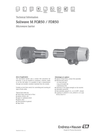
  • 1. Technical Information Soliwave M FQR50 / FDR50 Microwave barrier Advantages at a glance • Option of flush front, contact free assembly • Mechanically robust - no wear and tear - long serviceable life - maintenance free • Indication of the signal strength on the receiver • Adjustable sensitivity • Easy assembly using R 1½ - or 1½ NPT - thread • Conforms to ATEX II 1/2 D, ATEX II 1/2 G and IECEx Zone 0/1 TI00378F/97/EN/13.11 Area of application The microwave barrier uses a contact free procedure for detection. It can be installed in containers, conduits, shafts or on free fall shafts. It is possible to take a measurement through non-metallic container materials from the outside. Suitable as level limit switch for controlling and counting all types of bulk solids. Typical bulk solids are: • wood chips, wood dust or flour • plaster, cement, ash • paper or cardboard shred • gravel, sand • dried powders in general • bags, boxes
  • 2. 2 Soliwave M FQR50 / FDR50 Endress+Hauser Table of contents Function and system design ........................................ 3 Measuring principle ...................................................................... 3 Measuring system ......................................................................... 3 Equipment combinations ............................................................... 3 Input ........................................................................... 4 Measuring range (range of detection) ............................................. 4 Operating frequency ...................................................................... 4 Transmitter power ......................................................................... 4 Output ........................................................................ 4 Output signal ................................................................................ 4 Switching frequency FDR50 .......................................................... 4 Power supply .............................................................. 5 Electrical connection ..................................................................... 5 Ring wiring ................................................................................... 5 Star wiring .................................................................................... 5 Cable entry ................................................................................... 5 Cable gland ................................................................................... 6 Wire specification .......................................................................... 6 Operating conditions .................................................. 7 Installation instructions ................................................................. 7 Notes to orientation ...................................................................... 7 Minimum distance from emitter to receiver ................................... 7 Installation using reflectors ............................................................ 7 Parallel operation .......................................................................... 8 Relation between detection and minimum distance ........................................................................ 9 Direct installation with threaded connection ................................ 10 Bracket installation in front of microwave-permeable window ...... 11 Bracket installation in front of microwave-permeable window with danger of condensation on the container's inner wall ........... 11 Bracket installation in front of microwave-permeable sight glass fitting .................................................................................. 11 Angle installation on container .................................................... 12 Flange mounting using screw-in flange ........................................ 12 Flange mounting using screw-in flange for oblique conical containers ................................................................................... 12 Flange mounting using screw-in flange with danger of build-up ... 13 Installation with pipe as wave guide ............................................ 13 High-temperature application ...................................................... 14 Environment ............................................................. 15 Ambient temperature .................................................................. 15 Storage temperature .................................................................... 15 Degree of protection .................................................................... 15 Electromagnetic compatibility (EMC) .......................................... 15 Process ...................................................................... 15 Process temperature range ........................................................... 15 Process pressure .......................................................................... 15 Mechanical construction ........................................... 16 Design, dimensions F18-housing (aluminium) .............................. 16 Weight ........................................................................................ 16 Materials ..................................................................................... 16 Process connection ...................................................................... 16 Design, dimensions (stainless steel housing) ................................. 17 Weight ........................................................................................ 17 Material ...................................................................................... 17 Process connection ...................................................................... 17 Human interface ....................................................... 18 Display and operating elements (Receiver) ................................... 18 Calibration with covered path (switching point reached) .............. 19 Calibration with free path (switching point not reached) .............. 19 Configuration of the hysteresis ..................................................... 19 Calibration in applications with very low attenuation ................... 19 Display and operating elements (emitter) ..................................... 19 Certificates and approvals ......................................... 20 CE approval ................................................................................ 20 Ex approval ................................................................................. 20 Radio certification ....................................................................... 20 Other standards and guidelines .................................................... 20 Ordering information ................................................ 21 Ordering information Receiver FDR50 / Emitter FQR50 .............. 21 Comments regarding the product structure .................................. 21 Safety instructions ..................................................... 22 Zone classification ....................................................................... 22 General safety instructions for electrical equipment for hazardous areas .......................................................................... 22 Specific safety instructions ........................................................... 22 Accessories ............................................................... 23 Mounting bracket ....................................................................... 23 Adapter flange ............................................................................. 23 Installation flanges, material: 316Ti (stainless steel) ...................... 24 Sight glass fitting ......................................................................... 25 HT adapter and extension ........................................................... 27 Documentation ......................................................... 27 Operating instructions (KA) ......................................................... 27 Technical informations ................................................................ 27 Safety instructions ....................................................................... 27
  • 3. Soliwave M FQR50 / FDR50 Endress+Hauser 3 Function and system design Measuring principle The FQR50 emitter puts out the microwave signal via an integrated horn antenna. The FDR50 receiver directly opposite detects this signal and forwards a switching signal to the FTR325 evaluator. Alarm and control devices may be connected to these relay outputs. The range of the path is influenced by the different types of materials. The absorption of the microwaves here depends on the electric characteristics of the attenuating material. Materials with the capacity to conduct electricity, for example metals, reflect the waves and other materials with lower conductivity only weaken them or are even penetrated. The attenuation of the microwaves is reduced as the dielectric constant of the material to be emitted through becomes lower. FTR325 ReceiverEmitter Nivotester FTR325 Measuring system The complete measuring system for limit detection consists of: • an emitter FQR50, • a receiver FDR50 and • an evaluator Nivotester FTR325 Optical or acoustic signallers, contactors, relays, solenoids etc. may be connected to the Nivotester. Equipment combinations The emitter and receiver unit FQR50/FDR50-C* (ATEX II 1/2G Ex ia IIC T4 and ATEX II 1/2D Ex iaD 20/21 IP66 T98°C resp.) may only be combined with the Nivotester FTR325-B* (ATEX II (1)G [Ex ia] IIC and ATEX II (1)D [Ex iaD] resp.). The emitter and receiver unit FQR50/FDR50-D* (IECEx Zone 0/1 Ex ia IIC T4 and IECEx Ex iaD 20/21 IP66 T98°C resp.) may only be combined with the Nivotester FTR325-D* (IECEx [Zone 0] [Ex ia] IIC and IECEx [Ex iaD] resp.). Note: The devices FQR50/FDR50-A* (non hazardous area) and FQR50/FDR50-B* (ATEX II 1/2D IP66 T102°C) of the microwave barrier Soliwave M are no longer available, they have been replaced by the Soliwave FQR56/FDR56-AA* (non hazardous area) and FQR56/FDR56-BA* (ATEX II 1/2D Ex ta/tb IIIC T102°C Da/Db IP66). Please refer to the Technical Information TI00443F/97/EN for details about the new micro- wave barrier Soliwave. The following equipment combinations are impossible: • FQR50/FDR50-C* (ATEX II 1/2G Ex ia IIC T4 and ATEX II 1/2D Ex iaD 20/21 IP66 T98°C resp.) with Nivotester FTR325-A* (non hazardous area) • FQR50/FDR50-C* (ATEX II 1/2G Ex ia IIC T4 and ATEX II 1/2D Ex iaD 20/21 IP66 T98°C resp.) with Nivotester FTR325-D* (IECEx [Zone 0] [Ex ia] IIC and IECEx [Ex iaD] resp.) • FQR50/FDR50-D* (IECEx Zone 0/1 Ex ia IIC T4 and IECEx Ex iaD 20/21 IP66 T98°C resp.) with Nivotester FTR325-A* (non hazardous area) • FQR50/FDR50-D* (IECEx Zone 0/1 Ex ia IIC T4 and IECEx Ex iaD 20/21 IP66 T98°C resp.) with Nivotester FTR325-B* (ATEX II (1)G [Ex ia] IIC and ATEX II (1)D [Ex iaD] resp.)
  • 4. 4 Soliwave M FQR50 / FDR50 Endress+Hauser Input Measured variable Absorption of the electromagnetic waves produced by the FQR50 emitter. Measuring range (range of detection) When there is an unrestricted path between the emitter and the receiver the maximum range, depending on the version (see ordering information), is 8 m or 20 m. The range is also dependent on the container walls to be penetrated. Operating frequency 24.125 GHz Transmitter power The maximum power produced by the FQR50 emitter is 100 mW e.i.r.p. (equivalent isotrope radiation performance). • Power density directly in front of the emitter: 1 mW / cm2 • Power density at a distance of 1 m: 0.3 µW / cm2 Note: The power density is significantly below the recommended limit values of the ICNIRP guidelines "Guidelines for Limiting Exposure to Time-Varying Electric, Magnetic, and Electromagnetic Fields (up to 300 GHz)" and is thus harmless for humans! Output Output signal Switching signal for the Nivotester FTR325 Switching frequency FDR50 max. 2 Hz
  • 5. Soliwave M FQR50 / FDR50 Endress+Hauser 5 Power supply Electrical connection A suitable wire (see "Wire specification") is used to connect the emitter and receiver of the Soliwave M microwave barrier with the Nivotester FTR325. The following wiring variants are permitted: Ring wiring 6 7 8 6 7 8 1 2 1516 3 4 5 1 1 22 3 31 2 3 Emitter FQR50 Receiver FDR50 Contact circuit (terminal 3, 4, 5) and alarm output (terminal 15, 16) resp.: U = max. 253 V (AC) / 40 V (DC) I = max. 2 A P = max. 500 VA (cos φ ≥ 0.7) / 80 W Power supply (terminal 1, 2): A = 85 - 253 V (AC), 50/60 Hz E = 20 - 60 V (DC) 20 - 30 V (AC), 50/60 Hz FTR325 Star wiring 6 7 8 6 7 8 1 2 1516 3 4 5 1 1 22 3 31 2 3 Emitter FQR50 Receiver FDR50 Contact circuit (terminal 3, 4, 5) and alarm output (terminal 15, 16) resp.: U = max. 253 V (AC) / 40 V (DC) I = max. 2 A P = max. 500 VA (cos φ ≥ 0.7) / 80 W Power supply (terminal 1, 2): A = 85 - 253 V (AC), 50/60 Hz E = 20 - 60 V (DC) 20 - 30 V (AC), 50/60 Hz FTR325 Cable entry • M20 x 1.5 or • ½ NPT
  • 6. 6 Soliwave M FQR50 / FDR50 Endress+Hauser Cable gland • M20 x 1.5: - Degree of protection IP66 - Scope of supply: 2 Wire specification • Usual commercial installation wire • Conductor cross-section: max. 1.5 mm • Resistance: 15 Ω/km ≤ R' ≤ 150 Ω/km • Inductance: 0.4 mH/km ≤ L' ≤ 1 mH/km • Capacitance: 45 nF/km ≤ C' ≤ 200 nF/km • Length of spurs max. 1000 m (IIC) and 5000 m (IIB) respectively Example cable length Copper cable, specific resistance ρ = 0.0172 Ωmm2 /m, cross section 0.75mm2 It applies: R [Ω] = (ρ [Ωmm2 /m] * l [m]) / A [mm2 ] The maximum cable length is 1090 m.
  • 7. Soliwave M FQR50 / FDR50 Endress+Hauser 7 Operating conditions Installation instructions Both the FQR50 emitter and the FDR50 receiver are equipped with a standard thread (R 1½ in compliance with EN10226 and 1½" NPT in complience with ANSI/ASME B1.20.1) as a process connector. This makes a simple installation in the existing container sleeves or fittings possible. Note: • The fronts of the emitter and the receiver should face each other and be concentric. • Since the microwaves are polarised the FQR50 emitter and the FDR50 receiver may not be rotated around their longitudinal axis, unless they are rotated exactly 180°. • Disturbing reflections at metal parts are to be avoided. • An improvement in the signal quality can be achieved by an adjustable mounting of emitter and receiver of ± 15 mm along their longitudinal axis (see "Angle installation" on page 12). Notes to orientation Minimum distance from emitter to receiver A minimum distance of 30 mm should be maintained between the emitter and the receiver. Installation using reflectors If, for construction reasons, a direct confrontation of the FQR50 emitter and the FDR50 receiver is not pos- sible, the microwave beam can be redirected via a flat metal mirror (reflectors). By using reflectors the range of the microwave barrier is reduced by approximately 10% per reflector.
  • 8. 8 Soliwave M FQR50 / FDR50 Endress+Hauser ReflectorReflector Reflector Please make sure that FQR50 emitter and FDR50 receiver are placed at symmetrical angles toward the reflector (entry angle = exit angle), since otherwise the receiver will get no evaluable signal. Reflector Parallel operation It may be necessary to utilize several microwave barriers (each consisting of a FQR50 emitter, a FDR50 receiver and a FTR325 Nivotester) in one place (for example for detecting several limit states in a pipeline, see figure). To prevent interferences between the microwave paths, various modulation frequencies can be adjusted on the FQR50 emitter (as of production date July 2008). 1 2 3 3 2 1 Switch setting S1 Modulation frequency 1 (factory setting) 2 3
  • 9. Soliwave M FQR50 / FDR50 Endress+Hauser 9 The switch setting of S1 has no effect when using a single microwave barrier and can be any way. Regard the following advice for parallel use of several microwave barriers: - Use the differnt modulation frequencies in sequence, e.g. 1, 2, 3, 1, ... - Regard the minimum distance A depending on the detection distance D. - Rotate every other microwave barrier by 90° to eliminate interferences (see figure, pertains to emitter and receiver). A D Relation between detection and minimum distance The following relation between detection distance D and minimum distance between microwave barriers A applies to parallel operation of several barriers using emitters with selectable modulation frequency as shown in the figure. 10 20 30 40 50 60 70 80 90 100 110 120 130 140 150 160 170 180 190 200 210 45 40 35 30 25 20 15 10 5 0 A [cm] D [cm] Note: The values given in the diagramm relate to optimum installation conditions and may vary depending on the actual installation situation. The spacing of the microwave barriers may have to be adjusted with installations in sealed metal containers, funnels, or similar, due to occuring reflections for example.
  • 10. 10 Soliwave M FQR50 / FDR50 Endress+Hauser Installation examples Example 1: Bulk counting FTR325 Bulk good Emitter Receiver Evaluator FTR325 Example 2: Limit detection of bulk solids FTR325 Product Emitter Receiver Evaluator FTR325 Direct installation with threaded connection R 1½ / 1½ NPT
  • 11. Soliwave M FQR50 / FDR50 Endress+Hauser 11 Bracket installation in front of microwave- permeable window Mounting bracket *1 Bracket installation in front of microwave-permeable window with danger of condensation on the container's inner wall Bracket installation in front of microwave- permeable sight glass fitting Mounting bracket *1 Sight glass fitting *2 Mounting bracket *1 Sight glass fitting *2 A*3 Purge air *6
  • 12. 12 Soliwave M FQR50 / FDR50 Endress+Hauser Angle installation on container Mounting bracket *1 Securing arm max. 200 *4 Installation flange Ceramic disc (aluminium oxide) *1 Suitable installation brackets are available as accessories, see "Accessories" *2 Suitable microwave-permeable sight glass fittings are available as accessories, see "Accessories" *3 The distance A depends on the nominal diameter of the sight glass fitting (or the diameter of the sight glass) and the temperature at the fitting. To prevent possible signal attenuation, we recommend keeping the distance as short as possible (e. g. max. 40 mm at DN50). *4 Distance for temperature reduction between the process temperature and max. 70°C at the microwave barrier *5 Various installation adapters (e. g. for angle installation) are available as special equipment packages. *6 We recommend using purge air to prevent fouling (material accumulation) in the nozzle that is open to the process. Alternatively, you can also close the nozzle using a plastic plug. Flange mounting using screw-in flange L Plastic plug Installation flange *1 Note: • The maximum length L depends on the dielectric constant and the water absorption of the plastic materi- al. Observe the manufacturer's specifications. • We recommend PTFE as the material, as this allows the length at the emitter and receiver to be up to 300 mm. • For optimal orientation, the emitter and receiver should be able to be moved by ± 10 mm along their longitudinal axis. Flange mounting using screw-in flange for oblique conical containers
  • 13. Soliwave M FQR50 / FDR50 Endress+Hauser 13 Flange mounting using screw-in flange with danger of build-up Installation with pipe as wave guide L Note: • This type of mounting is recommended if conditions at the process or in the area surrounding the process are unfavorable (such as high temperatures or heavy contamination) or if the building's situation does not permit direct installation. • The pipe can be made of any desired metallic material, and the length L is unimportant due to the wave- guide effect. • Edges inside the pipe (for example at transitions) can cause signal attenuation and thus should be avoided wherever possible.
  • 14. 14 Soliwave M FQR50 / FDR50 Endress+Hauser High-temperature application For applications with process temperatures up to +450°C, the temperature reduction to max. +70°C takes place on the microwave barrier with a corresponding high-temperature adapter (with extension where necessary). The length of the adapter is based on the insulation thickness to be penetrated (if present) and the ambient conditions at the measuring point. Tmax = +70°CTP,max = +450°C Pmax = 80 ... 510 kPa abs. (0,8 ... 5,1 bar abs.) Wall Insulation HT adapter Extension X Note: • To maintain the maximum temperature of +70°C at the FQR50/FDR50, we recommend a minimum difference (X) of 200 mm between the process or the insulation and the devices. • The individual extensions can also be combined in any way desired. • We recommend the use of variants with a measuring range of max. 20 m, because each high- temperature adapter results in a reduction of the range.
  • 15. Soliwave M FQR50 / FDR50 Endress+Hauser 15 Environment Ambient temperature • -20°C ... +70°C Storage temperature • -40°C ... +80°C Degree of protection • With closed housing: IP 66 • With open housing: IP 20 Electromagnetic compatibility (EMC) • Interference Emission to EN 61326, Electrical Equipment Class B • Interference Immunity to EN 61326, Appendix A (Industrial) Process Process temperature range • -40°C to +70°C (without optional adapter for temperature reduction) • -40°C to +450°C (with optional adapter for temperature reduction, see Accessories) Process pressure • 80 to 480 kPa absolute (0.8 to 4.8 bar absolute) (Applies only when FQR50 emitter or FDR50 receiver is installed directly in the process.) • 80 to 510 kPa absolute (0.8 to 5.1 bar absolute) (Applies only when using the optional adapter for temperature reduction.)
  • 16. 16 Soliwave M FQR50 / FDR50 Endress+Hauser Mechanical construction Design, dimensions F18- housing (aluminium) Weight • 1.0 kg Materials • Housing: Aluminium • Process connection (fluid-wetted parts): - Stainless steel 316Ti/1.4571 - Sensor diaphragm: PTFE • Cable glands: PA Process connection • Thread R 1½ (EN 10226) or • 1½ NPT (ANSI/ASME B1.20.1)
  • 17. Soliwave M FQR50 / FDR50 Endress+Hauser 17 Design, dimensions (stainless steel housing) Weight • 2.1 kg Material • Housing: Stainless steel 316TI/1.4571 • Process connection (fluid-wetted parts): - Stainless steel 316Ti/1.4571 - Sensor diaphragm: PTFE • Cable glands: PA Process connection • Thread R 1½ (EN 10226) or • 1½ NPT (ANSI/ASME B1.20.1)
  • 18. 18 Soliwave M FQR50 / FDR50 Endress+Hauser Human interface By using frequencies in the 24 GHz range it is possible to detect products having low attenuation even with low amounts of bulk product between the emitter and the receiver. The calibration options of the units offer the necessary flexibility to be able to adjust the barrier to individual situations easily. • Rough/fine calibration (r, n) • Hysteresis p selected in 2 stages • LED field strength is displayed as an adjustment and positioning aid • LED for the switching output m and for operation status q (supply voltage is present) Display and operating elements (Receiver) 1 2 3 4 Bar Dot 1 2 3 4 1 2 3 4 1 2 3 4 1 2 3 4 Sensitivity minimum Sensitiivity maximum * factory setting * m r q p o n The microwave barrier Soliwave M is calibrated using 4 DIP switches for rough calibration r and a potenti- ometer for fine calibration n on the attenuation necessary for unambiguous product recognition. When there is sufficient attenuation or when the microwaves are interrupted by the product, the receiver reacts with an output (LED m) on the through connection to the external evaluator FTR325. Field status and operation status are indicated on the spot either by a bar graph or by a dot display o (switchable by p). • High sensitivity can be set for the detection of materials with a very high dielectric constant or of metals because then the beam is attenuated strongly enough or covered. • The sensitivity has to be adjusted precisely for the detection of materials with a low dielectric constant.
  • 19. Soliwave M FQR50 / FDR50 Endress+Hauser 19 Calibration with covered path (switching point reached) • The sensitivity of the microwave receiver FDR50 is to be adjusted in such a way that none, as a maximum however the first two LEDs in the LED line light up. If this should not be the case, the sensitivity is to be reduced appropriately. • With the path uncovered, LED 6 must light up in the LED line as a minimum. Calibration with free path (switching point not reached) • The sensitivity of the receiver FDR50 must be adjusted in such a way that as a maximum LED 10 just starts to light up, but at least LED 6 in the LED line must light up. • With the path covered, only LED 3 must light up in the LED line at the most. • After a few filling procedures, the sensitivity should be readjusted, if necessary, with the path covered. Configuration of the hysteresis Switch position large hysteresis Switch position small hysteresis Covered path Uncovered path Calibration in applications with very low attenuation Example: Paper shred Setting up with covered path • Reduce hysteresis: - adjust switch • Adjust sensitivity: - change the rough and fine calibration so that the LEDs 1 to 3 in the LED line light up. Display and operating elements (emitter) 1 2 3 3 2 1 m The emitter FQR50 has a green LED m, that signals the operating status (supply voltage present).
  • 20. 20 Soliwave M FQR50 / FDR50 Endress+Hauser Certificates and approvals CE approval The Soliwave M microwave barrier is in conformity with the statutory requirements of the EC Directives. The manufacturer confirms successful testing of the device by affixing to it the CE mark. Ex approval ATEX II 1/2D Ex iaD 20/21 IP66 T98°C (Certification number: BVS 07 ATEX E 148 X) ATEX II 1/2G Ex ia IIC T4 (Certification number: BVS 07 ATEX E 148 X) IECEx Zone 0/1 Ex ia IIC T4 (Certification number: IECEx BVS 09.0007X) IECEx Ex iaD 20/21 IP66 T98°C (Certification number: IECEx BVS 09.0007X) Radio certification RTTE according to EN 300440-2 FCC [FCC ID UAS-FQR50] Other standards and guidelines Directive 1999/05/EC Article 3.1 (a) and 3.1 (b) and the included Directives 73/23/EEC and 89/336/EEC
  • 21. Soliwave M FQR50 / FDR50 Endress+Hauser 21 Ordering information Ordering information Receiver FDR50 / Emitter FQR50 10 Approval: C ATEX II 1/2G Ex ia IIC T4 ATEX II 1/2D Ex iaD 20/21 IP66 T98°C D IECEx Zone 0/1 Ex ia IIC T4 IECEx Ex iaD 20/21 IP66 T98°C Y Special version, to be specified 20 Distance emitter/receiver: 1 Measuring range *1 maximum 8 m 2 Measuring range *1 maximum 20 m 9 Special version, to be specified 30 Process connection and material: R Thread R 1½ EN10226, stainless steel 316Ti S Thread 1½ NPT ANSI/ASME, stainless steel 316Ti Y Special version, to be specified 40 Housing and cable entry: D Aluminium F18-housing IP66, M20x1.5 F Aluminium F18-housing IP66, ½ NPT G Stainless steel 316Ti, IP66, M20x1.5 H Stainless steel 316Ti, IP66, ½ NPT Y Special version, to be specified 50 Optional features: A Basic equipment Y Special version, to be specified FDR50/FDR50 - *1 Please select the same version for emitter FQR50 and receiver FDR50 Comments regarding the product structure Only the following device combinations are possible: • FQR50/FDR50-C* with FTR325-B* • FQR50/FDR50-D* with FTR325-D*
  • 22. 22 Soliwave M FQR50 / FDR50 Endress+Hauser Safety instructions Zone classification FTR325FTR325 Non hazardous area Hazardous area FTR325-B* Emitter FQR50-C* Receiver FDR50-C* Zone 0 / Zone 20 Zone 1 / Zone 21 FTR325-D* Emitter FQR50-D* Receiver FDR50-D* Zone 0 / Zone 20 Zone 1 / Zone 21 General safety instructions for electrical equipment for hazardous areas • Install it according to manufacturer's specifications and the standards and regulations applicable in your area. • Installation, electrical connection, commissioning, operation and, if necessary, maintenance may be carried out only by trained specialists authorized to do so by the facility's owner-operator. • Do not operate the devices of the microwave barrier outside of the electrical, thermal or mechanical cha- racteristic quantities. • Seal unused entry glands with approved sealing plugs that correspond to the type of protection. The plastic transportation plug does not meet this requirement and must therefore be changed during the installation process. • For additional safety instructions, refer to the XA00219F (FQR50/FDR50-C*) or XA00484F (FQR50/FDR50-D*). Specific safety instructions • The emitter/receiver unit FQR50/FDR50-C* may only be combined with the Nivotester FTR325-B*. • The emitter/receiver unit FQR50/FDR50-D* may only be combined with the Nivotester FTR325-D*.
  • 23. Soliwave M FQR50 / FDR50 Endress+Hauser 23 Accessories Mounting bracket The FQR50 emitter and FDR50 receiver can be easily installed on existing frames using a mounting bracket. Mounting bracket for frame mounting • Aluminum material: Part number 52017501 • Plastic material: Part number 52017502 M6 / ¼ UNC86 66 66 66 Adapter flange The screw assembly of the microwave barrier Soliwave M is possible by an aluminium adapter flange (directly compatible to the microwave barrier QR30/DR30) or by a DIN flange. Adapter flange (directly compatible to the microwave barrier QR30/DR30) • DN 40 PN 6, connection dimensions according to DIN EN 1092-1, material aluminium, with Rp 1½ thread: Part number 71006345 • 1½ 150 lbs, connection dimensions according to ANSI/ASME B16.5, material aluminium, with 1½ NPT thread: Part number 71006346
  • 24. 24 Soliwave M FQR50 / FDR50 Endress+Hauser Installation flanges, material: 316Ti (stainless steel) Connection dimensions to DIN EN 1092-1, with Rp 1½ internal thread: • DN40 PN16 Part number 71006348 with inspection certificate to EN 10204-3.1 Part number 71108383 • DN50 PN16 Part number 71006350 with inspection certificate to EN 10204-3.1 Part number 71108388 • DN100 PN16 Part number 71006352 with inspection certificate to EN 10204-3.1 Part number 71108390 d3 Rp1½ d2 d1 D Flange d1/ mm d2/ mm d3/ mm D/ mm Number of holes DN40/PN16 110 150 18 16 4 DN50/PN16 125 165 18 18 4 DN100/PN16 180 220 18 20 8 Connection dimensions to ANSI/ASME B16.5, with 1½ NPT internal thread: • 1½ 150 lbs Part number 71006349 with inspection certificate to EN 10204-3.1 Part number 71108387 • 2 150 lbs Part number 71006351 with inspection certificate to EN 10204-3.1 Part number 71108389 • 4 150 lbs Part number 71006353 with inspection certificate to EN 10204-3.1 Part number 71108391 d3 1½NPT Flange d1/ mm d2/ mm d3/ mm D/ mm Number of holes 1½ 150 lbs 98.6 127 15.7 17.5 4 2 150 lbs 120.7 152.4 19.1 19.1 4 4 150 lbs 190.5 228.6 19.1 23.9 8 d1 d2 D
  • 25. Soliwave M FQR50 / FDR50 Endress+Hauser 25 Sight glass fitting Screw-type fitting similar to DIN 11851, materials: stainless steel 304, silicone and C4400, Pmax = 600 kPa (6 bar), Tmax = 200°C, borosilicate glass, screw-on installation, thread adapter nut d2 D A DN d1/ mm d2/ mm s/ mm D/ mm d/ mm A/ mm a/ mm 50 50 63 10 92 61 44 21 80 80 94 12 127 93 57 25 100 100 113 15 148 114 69 34 d1 DN d sa • DN 50 Part number 71026440 • DN 80 Part number 71026441 • DN 100 Part number 71026442 Weld-in fitting for unpressurized containers, materials: stainless steel 316Ti and silicone, Tmax = 200°C, borosilicate glass, screw-on installation DN d1/ mm d2/ mm D/ mm k/ mm d3/ mm 50 80 100 140 120 102 80 100 125 165 145 127 100 125 150 190 170 152 d2 d3 d1 k D 10 15 • DN 50 Part number 71026443 • DN 80 Part number 71026444 • DN 100 Part number 71026445
  • 26. 26 Soliwave M FQR50 / FDR50 Endress+Hauser Weld-in fitting to DIN 28120, materials: stainless steel 316Ti/321 and silicone, Pmax = 1 MPa (10 bar), Tmax = 200°C, borosilicate glass, screw-on installation k D DN d1/ mm d2/ mm D/ mm k/ mm h1/ mm d3/ mm 50 80 100 165 125 16 102 80 100 125 200 160 20 127 100 125 150 220 180 22 152 d1 d2 d3 h130 45° • DN 50 Part number 71026446 • DN 80 Part number 71026447 • DN 100 Part number 71026448 Flange fitting to DIN 28121 for screwing onto existing counterflanges, materials: stainless steel 316Ti, PTFE and C4400, Pmax = 2.5 MPa (25 bar), Tmax = 200°C, borosilicate glass d10 DN d1/ mm d3/ mm s/ mm D/ mm k/ mm h3/ mm d9/ mm d10/ mm 50 65 80 15 165 125 41 18 82 80 80 100 20 200 160 50 18 102 100 100 125 25 235 190 59 22 127 h3 7 d3 d1 d9 k D d1 d10 Gasket (product side) s • DN 50 Part number 71026449 • DN 80 Part number 71026450 • DN 100 Part number 71026451
  • 27. Soliwave M FQR50 / FDR50 Endress+Hauser 27 HT adapter and extension R1½/1½NPT 170 L m n HT adapter m with flush-mounted ceramic disk: • Thread R 1½ or Rp 1½, 55mm hex, 316Ti/1.4571 Part number 71113441 • Thread 1½ NPT, 55mm hex, 316Ti/1.4571 Part number 71113449 Extension for HT adapter n: • Thread R 1½ or Rp 1½, 55mm hex, 316Ti/1.4571 L = 225 mm Part number 71113450 L = 325 mm Part number 71113451 L = 525 mm Part number 71113452 • Thread 1½ NPT, 55mm hex, 316Ti/1.4571 L = 225 mm Part number 71113453 L = 325 mm Part number 71113454 L = 525 mm Part number 71113455 Documentation Operating instructions (KA) Soliwave M FQR50/FDR50 KA00206F/97/A6 Nivotester FTR325 KA00205F/97/A6 Technical informations Nivotester FTR325 TI00377F/97/EN Safety instructions Soliwave M FQR50/FDR50-C* with the Nivotester FTR325-B* XA00219F/97/A3 Soliwave M FQR50/FDR50-D* with the Nivotester FTR325-D* XA00484F/97/EN
  • 28. 28 Soliwave M FQR50 / FDR50 Endress+Hauser Instruments International Endress+Hauser Instruments International AG Kaegenstrasse 2 4153 Reinach Switzerland Tel.+41 61 715 81 00 Fax+41 61 715 25 00 www.endress.com info@ii.endress.com TI00378F/97/EN/13.11 InDesign 6.0.6 Subject to modification