SlideShare uma empresa Scribd logo
1 de 28
Problem 304 
A steel shaft 3 ft long that has a diameter of 4 in is subjected to a torque of 15 kip·ft. Determine the 
maximum shearing stress and the angle of twist. Use G = 12 × 106 psi. 
Solution 304 
HideClick here to show or hide the solution 
answer 
answer 
- See more at: http://www.mathalino.com/reviewer/mechanics-and-strength-of-materials/solution-to-problem- 
304-torsion#sthash.7et6x2qh.dpuf 
Problem 305 
What is the minimum diameter of a solid steel shaft that will not twist through more than 3° in a 6 -m 
length when subjected to a torque of 12 kN·m? What maximum shearing stress is developed? Use 
G = 83 GPa. 
Solution 305 
HideClick here to show or hide the solution 
answer 
answer 
- See more at: http://www.mathalino.com/reviewer/mechanics-and-strength-of-materials/solution-to-problem- 
305-torsion#sthash.xuscbNTO.dpuf
Problem 306 
A steel marine propeller shaft 14 in. in diameter and 18 ft long is used to transmit 5000 hp at 189 
rpm. If G = 12 × 106 psi, determine the maximum shearing stress. 
Solution 306 
HideClick here to show or hide the solution 
answer 
- See more at: http://www.mathalino.com/reviewer/mechanics-and-strength-of-materials/solution-to-problem- 
306-torsion#sthash.gWIzxTKY.dpuf 
Problem 307 
A solid steel shaft 5 m long is stressed at 80 MPa when twisted through 4°. Using G = 83 GPa, 
compute the shaft diameter. What power can be transmitted by the shaft at 20 Hz? 
Solution 307 
HideClick here to show or hide the solution 
answer
answer 
- See more at: http://www.mathalino.com/reviewer/mechanics-and-strength-of-materials/solution-to-problem- 
307-torsion#sthash.fLkmgj20.dpuf 
Problem 308 
A 2-in-diameter steel shaft rotates at 240 rpm. If the shearing stress is limited to 12 ksi, determine 
the maximum horsepower that can be transmitted. 
Solution 308 
HideClick here to show or hide the solution 
answer 
- See more at: http://www.mathalino.com/reviewer/mechanics-and-strength-of-materials/solution-to-problem- 
308-torsion#sthash.uqfrC5Oy.dpuf 
Problem 309 
A steel propeller shaft is to transmit 4.5 MW at 3 Hz without exceeding a shearing stress of 50 MPa 
or twisting through more than 1° in a length of 26 diameters. Compute the proper diameter if G = 83 
GPa. 
Solution 309 
HideClick here to show or hide the solution
Based on maximum allowable shearing stress: 
Based on maximum allowable angle of twist: 
Use the larger diameter, thus, d = 352 mm. answer 
- See more at: http://www.mathalino.com/reviewer/mechanics-and-strength-of-materials/solution-to-problem- 
309-torsion#sthash.o0ktq1Mp.dpuf 
Problem 310 
Show that the hollow circular shaft whose inner diameter is half the outer diameter has a torsional 
strength equal to 15/16 of that of a solid shaft of the same outside diameter. 
Solution 310 
HideClick here to show or hide the solution 
Hollow circular shaft: 
Solid circular shaft:
(okay!) 
- See more at: http://www.mathalino.com/reviewer/mechanics-and-strength-of-materials/solution-to-problem- 
310-torsion#sthash.5JhAkxrA.dpuf 
Problem 311 
An aluminum shaft with a constant diameter of 50 mm is loaded by torques applied to gears 
attached to it as shown in Fig. P-311. Using G = 28 GPa, determine the relative angle of twist of gear 
D relative to gear A. 
Solution 311 
HideClick here to show or hide the solution 
Rotation of D relative to A:
answer 
- See more at: http://www.mathalino.com/reviewer/mechanics-and-strength-of-materials/solution-to-problem- 
311-torsion#sthash.m2vqDvnC.dpuf 
Problem 312 
A flexible shaft consists of a 0.20-in-diameter steel wire encased in a stationary tube that fits closely 
enough to impose a frictional torque of 0.50 lb·in/in. Determine the maximum length of the shaft if 
the shearing stress is not to exceed 20 ksi. What will be the angular deformation of one end relative 
to the other end? G = 12 × 106 psi. 
Solution 312 
HideClick here to show or hide the solution 
If θ = dθ, T = 0.5L and L = dL 
answer
- See more at: http://www.mathalino.com/reviewer/mechanics-and-strength-of-materials/solution-to-problem- 
312-torsion#sthash.IMY9oI8U.dpuf 
Problem 313 
Determine the maximum torque that can be applied to a hollow circular steel shaft of 100 -mm 
outside diameter and an 80-mm inside diameter without exceeding a shearing stress of 60 MPa or a 
twist of 0.5 deg/m. Use G = 83 GPa. 
Solution 313 
HideClick here to show or hide the solution 
Based on maximum allowable shearing stress: 
Based on maximum allowable angle of twist: 
Use the smaller torque, T = 4 198.28 N·m. answer 
- See more at: http://www.mathalino.com/reviewer/mechanics-and-strength-of-materials/solution-to-problem- 
313-torsion#sthash.glMBmcRC.dpuf 
Problem 314 
The steel shaft shown in Fig. P-314 rotates at 4 Hz with 35 kW taken off at A, 20 kW removed at B, 
and 55 kW applied at C. Using G = 83 GPa, find the maximum shearing stress and the angle of 
rotation of gear A relative to gear C.
Solution 314 
HideClick here to show or hide the solution 
Relative to C: 
∴ answer
answer 
- See more at: http://www.mathalino.com/reviewer/mechanics-and-strength-of-materials/solution-to-problem- 
314-torsion#sthash.GZRzQW6J.dpuf 
Problem 315 
A 5-m steel shaft rotating at 2 Hz has 70 kW applied at a gear that is 2 m from the left end where 20 
kW are removed. At the right end, 30 kW are removed and another 20 kW leaves the shaft at 1.5 m 
from the right end. (a) Find the uniform shaft diameter so that the shearing stress will not exceed 60 
MPa. (b) If a uniform shaft diameter of 100 mm is specified, determine the angle by which one end of 
the shaft lags behind the other end. Use G = 83 GPa. 
Solution 315 
HideClick here to show or hide the solution
Part (a) 
For AB 
For BC 
For CD 
Use d = 69.6 mm answer 
Part (b) 
answer 
- See more at: http://www.mathalino.com/reviewer/mechanics-and-strength-of-materials/solution-to-problem- 
315-torsion#sthash.fBhMEs49.dpuf 
Problem 316 
A compound shaft consisting of a steel segment and an aluminum segment is acted upon by two 
torques as shown in Fig. P-316. Determine the maximum permissible value of T subject to the 
following conditions: τst ≤ 83 MPa, τal ≤ 55 MPa, and the angle of rotation of the free end is limited to 
6°. For steel, G = 83 GPa and for aluminum, G = 28 GPa.
Solution 316 
HideClick here to show or hide the solution 
Based on maximum shearing stress, τmax = 16T / πd3: 
Steel 
Aluminum 
Based on maximum angle of twist, θmax = 6°:
Use the least value of T. Thus, T = 679.04 N·m answer 
- See more at: http://www.mathalino.com/reviewer/mechanics-and-strength-of-materials/solution-to-problem- 
316-torsion#sthash.AgjqEvBj.dpuf 
Problem 317 
A hollow bronze shaft of 3 in. outer diameter and 2 in. inner diameter is slipped over a solid steel 
shaft 2 in. in diameter and of the same length as the hollow shaft. The two shafts are then fastened 
rigidly together at their ends. For bronze, G = 6 × 10⁶ psi, and for steel, G = 12 × 106 psi. What 
torque can be applied to the composite shaft without exceeding a shearing stress of 8000 psi in the 
bronze or 12 ksi in the steel? 
Solution 317 
HideClick here to show or hide the solution 
→ Equation (1) 
Applied Torque = Resisting Torque 
→ Equation (2) 
Equation (1) with Tst in terms of Tbr and Equation (2) 
Equation (1) with Tbr in terms of Tst and Equation (2)
Based on hollow bronze (Tbr = 0.6701T) 
Based on steel core (Tst = 0.3299T): 
Use T = 4232.44 lb·ft. answer 
- See more at: http://www.mathalino.com/reviewer/mechanics-and-strength-of-materials/solution-to-problem- 
317-torsion#sthash.0I4Fdv3a.dpuf 
Problem 318 
A solid aluminum shaft 2 in. in diameter is subjected to two torques as shown in Fig. P-318. 
Determine the maximum shearing stress in each segment and the angle of rotation of the free end. 
Use G = 4 × 10⁶ psi. 
Solution 318 
HideClick here to show or hide the solution
For the 2-ft segment: 
answer 
For the 3-ft segment: 
answer 
Angle of twist 
answer 
- See more at: http://www.mathalino.com/reviewer/mechanics-and-strength-of-materials/solution-to-problem- 
318-torsion#sthash.927Wj3R2.dpuf 
Problem 319 
The compound shaft shown in Fig. P-319 is attached to rigid supports. For the bronze segment AB, 
the diameter is 75 mm, τ ≤ 60 MPa, and G = 35 GPa. For the steel segment BC, the diameter is 50 
mm, τ ≤ 80 MPa, and G = 83 GPa. If a = 2 m and b = 1.5 m, compute the maximum torque T that 
can be applied.
Solution 319 
HideClick here to show or hide the solution 
→ Equation (1) 
→ Equation (2a) 
→ Equation (2b) 
Based on τbr ≤ 60 MPa 
→ Maximum allowable torque for bronze 
From Equation (2b)
Based on τbr ≤ 80 MPa 
→ Maximum allowable torque for steel 
From Equation (2a) 
From Equation (1), use Tbr = 3.142 kN·m and Tst = 1.963 kN·m 
answer 
- See more at: http://www.mathalino.com/reviewer/mechanics-and-strength-of-materials/solution-to-problem- 
319-torsion#sthash.ItnLWiwi.dpuf 
Problem 320 
In Prob. 319, determine the ratio of lengths b/a so that each material will be stressed to its 
permissible limit. What torque T is required? 
Solution 320 
HideClick here to show or hide the solution 
From the solution of Problem 319: 
Maximum Tbr = 4.970 kN·m 
Maximum Tst = 1.963 kN·m
answer 
- See more at: http://www.mathalino.com/reviewer/mechanics-and-strength-of-materials/solution-to-problem- 
320-torsion#sthash.6nxUFdzn.dpuf 
Problem 321 
A torque T is applied, as shown in Fig. P-321, to a solid shaft with built-in ends. Prove that the 
resisting torques at the walls are T1 = Tb/L and T2 = Ta/L. How would these values be changed if the 
shaft were hollow? 
Solution 321 
HideClick here to show or hide the solution 
→ Equation (1) 
→ Equation (2a) 
→ Equation (2b) 
Equations (1) and (2b):
(okay!) 
Equations (1) and (2a): 
(okay!) 
If the shaft were hollow, Equation (1) would be the same and the equality θ1 = θ2, by direct 
investigation, would yield the same result in Equations (2a) and (2b). Therefore, the values of 
T1 and T2 are the same (no change) if the shaft were hollow. 
- See more at: http://www.mathalino.com/reviewer/mechanics-and-strength-of-materials/solution-to-problem- 
321-torsion#sthash.MohyNe5b.dpuf 
Problem 322 
A solid steel shaft is loaded as shown in Fig. P-322. Using G = 83 GPa, determine the required 
diameter of the shaft if the shearing stress is limited to 60 MPa and the angle of rotation at the free 
end is not to exceed 4 deg. 
Solution 322 
HideClick here to show or hide the solution 
Based on maximum allowable shear:
For the 1st segment: 
For the 2nd segment: 
Based on maximum angle of twist: 
Use answer 
- See more at: http://www.mathalino.com/reviewer/mechanics-and-strength-of-materials/solution-to-problem- 
322-torsion#sthash.OWug7nMw.dpuf 
Problem 323 
A shaft composed of segments AC, CD, and DB is fastened to rigid supports and loaded as shown 
in Fig. P-323. For bronze, G = 35 GPa; aluminum, G = 28 GPa, and for steel, G = 83 GPa. 
Determine the maximum shearing stress developed in each segment.
Solution 323 
HideClick here to show or hide the solution 
Stress developed in each segment with respect to TA: 
The rotation of B relative to A is zero.
(okay!) 
answer 
answer 
answer 
- See more at: http://www.mathalino.com/reviewer/mechanics-and-strength-of-materials/solution-to-problem- 
323-torsion#sthash.dubUyY3F.dpuf 
Problem 324 
The compound shaft shown in Fig. P-324 is attached to rigid supports. For the bronze segment AB, 
the maximum shearing stress is limited to 8000 psi and for the steel segment BC, it is limited to 12 
ksi. Determine the diameters of each segment so that each material will be simultaneously stressed 
to its permissible limit when a torque T = 12 kip·ft is applied. For bronze, G = 6 × 10⁶ psi and for 
steel, G = 12 × 106 psi. 
Solution 324 
HideClick here to show or hide the solution
For bronze: 
For steel: 
→ Equation (1)
From Equation (1) 
answer 
answer 
- See more at: http://www.mathalino.com/reviewer/mechanics-and-strength-of-materials/solution-to-problem- 
324-torsion#sthash.74dyRe8X.dpuf 
Problem 325 
The two steel shaft shown in Fig. P-325, each with one end built into a rigid support have flanges 
rigidly attached to their free ends. The shafts are to be bolted together at their flanges. However, 
initially there is a 6° mismatch in the location of the bolt holes as shown in the figure. Determine the 
maximum shearing stress in each shaft after the shafts are bolted together. Use G = 12 × 106 psi 
and neglect deformations of the bolts and flanges. 
Solution 325 
HideClick here to show or hide the solution
answer 
answer 
- See more at: http://www.mathalino.com/reviewer/mechanics-and-strength-of-materials/solution-to-problem- 
325-torsion#sthash.rR8XqYaz.dpuf 
Problem 337 
A torque of 600 N·m is applied to the rectangular section shown in Fig. P-337. Determine the wall 
thickness t so as not to exceed a shear stress of 80 MPa. What is the shear stress in the short 
sides? Neglect stress concentration at the corners. 
Solution 337 
HideClick here to show or hide the solution 
Where: 
answer 
At any convenient center O within the section, the farthest side is the shorter one, thus, it is 
induced with the maximum allowable shear stress of 80 MPa. 
- See more at: http://www.mathalino.com/reviewer/mechanics-and-strength-of-materials/solution-to-problem- 
337-torsion-of-thin-walled-tube#sthash.NayevjH1.dpuf
Problem 338 
A tube 0.10 in. thick has an elliptical shape shown in Fig. P-338. What torque will cause a shearing 
stress of 8000 psi? 
Solution 338 
HideClick here to show or hide the solution 
Where: 
answer 
- See more at: http://www.mathalino.com/reviewer/mechanics-and-strength-of-materials/solution-to-problem- 
338-torsion-of-thin-walled-tube#sthash.DlHovKOp.dpuf
Problem 339 
A torque of 450 lb·ft is applied to the square section shown in Fig. P-339. Determine the smallest 
permissible dimension a if the shearing stress is limited to 6000 psi. 
Problem 339 
HideClick here to show or hide the solution 
Where: 
answer 
- See more at: http://www.mathalino.com/reviewer/mechanics-and-strength-of-materials/solution-to-problem- 
339-torsion-of-thin-walled-tube#sthash.KMfdcv2w.dpuf 
Problem 340 
A tube 2 mm thick has the shape shown in Fig. P-340. Find the shearing stress caused by a torque 
of 600 N·m.
Solution 340 
HideClick here to show or hide the solution 
Where: 
answer 
- See more at: http://www.mathalino.com/reviewer/mechanics-and-strength-of-materials/solution-to-problem- 
340-torsion-of-thin-walled-tube#sthash.vlSNH5IP.dpuf 
Problem 341 
Derive the torsion formula τ = Tρ / J for a solid circular section by assuming the section is composed 
of a series of concentric thin circular tubes. Assume that the shearing stress at any point is 
proportional to its radial distance. 
Solution 341 
HideClick here to show or hide the solution 
Where:
and it follows that (okay!) 
- See more at: http://www.mathalino.com/reviewer/mechanics-and-strength-of-materials/solution-to-problem- 
341-torsion-of-thin-walled-tube#sthash.DtqK6K15.dpuf

Mais conteúdo relacionado

Mais procurados

3_hydrostatic-force_tutorial-solution(1)
3_hydrostatic-force_tutorial-solution(1)3_hydrostatic-force_tutorial-solution(1)
3_hydrostatic-force_tutorial-solution(1)Diptesh Dash
 
Fluid mechanic white (cap2.1)
Fluid mechanic   white (cap2.1)Fluid mechanic   white (cap2.1)
Fluid mechanic white (cap2.1)Raul Garcia
 
Thermo problem set no. 1
Thermo problem set no. 1Thermo problem set no. 1
Thermo problem set no. 1Yuri Melliza
 
Simple Stress: Normal Stress
Simple Stress: Normal StressSimple Stress: Normal Stress
Simple Stress: Normal StressLk Rigor
 
Design of machine elements - DESIGN FOR SIMPLE STRESSES
Design of machine elements - DESIGN FOR SIMPLE STRESSESDesign of machine elements - DESIGN FOR SIMPLE STRESSES
Design of machine elements - DESIGN FOR SIMPLE STRESSESAkram Hossain
 
Tutorial # 3 +solution
Tutorial # 3  +solution Tutorial # 3  +solution
Tutorial # 3 +solution Eng. Ali Zekri
 
Chapter 5-cables and arches
Chapter 5-cables and archesChapter 5-cables and arches
Chapter 5-cables and archesISET NABEUL
 
Mecanica
MecanicaMecanica
MecanicaGlobal
 
Solucion tutoria 4 2017
Solucion tutoria 4 2017Solucion tutoria 4 2017
Solucion tutoria 4 2017Steven Jimenez
 
Fluid mechanics ( 2019 2020)
Fluid mechanics ( 2019 2020)Fluid mechanics ( 2019 2020)
Fluid mechanics ( 2019 2020)Yuri Melliza
 
Unit 3 Fluid Static
Unit 3 Fluid StaticUnit 3 Fluid Static
Unit 3 Fluid StaticMalaysia
 
Solution 2 3_8_bar_with_a_hole
Solution 2 3_8_bar_with_a_holeSolution 2 3_8_bar_with_a_hole
Solution 2 3_8_bar_with_a_holePraditaFirmansyah
 
Design for flexure and shear (rectangular & square section)
Design for flexure and shear (rectangular & square section)Design for flexure and shear (rectangular & square section)
Design for flexure and shear (rectangular & square section)Muhammad Bilal
 
Lec06 Analysis and Design of T Beams (Reinforced Concrete Design I & Prof. Ab...
Lec06 Analysis and Design of T Beams (Reinforced Concrete Design I & Prof. Ab...Lec06 Analysis and Design of T Beams (Reinforced Concrete Design I & Prof. Ab...
Lec06 Analysis and Design of T Beams (Reinforced Concrete Design I & Prof. Ab...Hossam Shafiq II
 

Mais procurados (20)

Ge 105 lecture 2 (TAPING CORRECTION) by: Broddett B. Abatayo
Ge 105 lecture 2 (TAPING CORRECTION) by: Broddett B. AbatayoGe 105 lecture 2 (TAPING CORRECTION) by: Broddett B. Abatayo
Ge 105 lecture 2 (TAPING CORRECTION) by: Broddett B. Abatayo
 
70148
70148 70148
70148
 
3_hydrostatic-force_tutorial-solution(1)
3_hydrostatic-force_tutorial-solution(1)3_hydrostatic-force_tutorial-solution(1)
3_hydrostatic-force_tutorial-solution(1)
 
Fluid mechanic white (cap2.1)
Fluid mechanic   white (cap2.1)Fluid mechanic   white (cap2.1)
Fluid mechanic white (cap2.1)
 
Thermo problem set no. 1
Thermo problem set no. 1Thermo problem set no. 1
Thermo problem set no. 1
 
Simple Stress: Normal Stress
Simple Stress: Normal StressSimple Stress: Normal Stress
Simple Stress: Normal Stress
 
Design of machine elements - DESIGN FOR SIMPLE STRESSES
Design of machine elements - DESIGN FOR SIMPLE STRESSESDesign of machine elements - DESIGN FOR SIMPLE STRESSES
Design of machine elements - DESIGN FOR SIMPLE STRESSES
 
Tutorial # 3 +solution
Tutorial # 3  +solution Tutorial # 3  +solution
Tutorial # 3 +solution
 
Chapter 5-cables and arches
Chapter 5-cables and archesChapter 5-cables and arches
Chapter 5-cables and arches
 
Chap 03
Chap 03Chap 03
Chap 03
 
Mecanica
MecanicaMecanica
Mecanica
 
Solucion tutoria 4 2017
Solucion tutoria 4 2017Solucion tutoria 4 2017
Solucion tutoria 4 2017
 
Fluids in Physics
Fluids in PhysicsFluids in Physics
Fluids in Physics
 
Fluid mechanics ( 2019 2020)
Fluid mechanics ( 2019 2020)Fluid mechanics ( 2019 2020)
Fluid mechanics ( 2019 2020)
 
Friction full
Friction fullFriction full
Friction full
 
Unit 3 Fluid Static
Unit 3 Fluid StaticUnit 3 Fluid Static
Unit 3 Fluid Static
 
Torsion
TorsionTorsion
Torsion
 
Solution 2 3_8_bar_with_a_hole
Solution 2 3_8_bar_with_a_holeSolution 2 3_8_bar_with_a_hole
Solution 2 3_8_bar_with_a_hole
 
Design for flexure and shear (rectangular & square section)
Design for flexure and shear (rectangular & square section)Design for flexure and shear (rectangular & square section)
Design for flexure and shear (rectangular & square section)
 
Lec06 Analysis and Design of T Beams (Reinforced Concrete Design I & Prof. Ab...
Lec06 Analysis and Design of T Beams (Reinforced Concrete Design I & Prof. Ab...Lec06 Analysis and Design of T Beams (Reinforced Concrete Design I & Prof. Ab...
Lec06 Analysis and Design of T Beams (Reinforced Concrete Design I & Prof. Ab...
 

Destaque

Strength of materials by singer and pytel (4th edt)
Strength of materials by singer and pytel (4th edt) Strength of materials by singer and pytel (4th edt)
Strength of materials by singer and pytel (4th edt) Abdullah Al Naser
 
strength of materials singer and pytel solution manual (chapter 9 )
strength of materials singer and pytel solution manual (chapter 9 )strength of materials singer and pytel solution manual (chapter 9 )
strength of materials singer and pytel solution manual (chapter 9 )Ahmad Haydar
 
Chap#5 Stresses in Beams solutions
Chap#5 Stresses in Beams solutionsChap#5 Stresses in Beams solutions
Chap#5 Stresses in Beams solutionsrnkhan
 
Chap#6 Beam Deflections solutions
Chap#6 Beam Deflections solutionsChap#6 Beam Deflections solutions
Chap#6 Beam Deflections solutionsrnkhan
 
Properties of surfaces-Centre of gravity and Moment of Inertia
Properties of surfaces-Centre of gravity and Moment of InertiaProperties of surfaces-Centre of gravity and Moment of Inertia
Properties of surfaces-Centre of gravity and Moment of InertiaJISHNU V
 
Centroids moments of inertia
Centroids moments of inertiaCentroids moments of inertia
Centroids moments of inertiacoolzero2012
 
Mechanics of materials solution manual (3 rd ed , by beer, johnston, & dewolf)
Mechanics of materials solution manual (3 rd ed , by beer, johnston, & dewolf)Mechanics of materials solution manual (3 rd ed , by beer, johnston, & dewolf)
Mechanics of materials solution manual (3 rd ed , by beer, johnston, & dewolf)Pawnpac
 
Civil Engineering (Beams,Columns)
Civil Engineering (Beams,Columns)Civil Engineering (Beams,Columns)
Civil Engineering (Beams,Columns)mbrsalman
 

Destaque (17)

Polytechnic of namibia ...
Polytechnic of namibia                                                       ...Polytechnic of namibia                                                       ...
Polytechnic of namibia ...
 
Mom lab revised
Mom lab revisedMom lab revised
Mom lab revised
 
Elc pre lab 2 complete
Elc pre lab 2 completeElc pre lab 2 complete
Elc pre lab 2 complete
 
Report 3
Report 3Report 3
Report 3
 
Okori
OkoriOkori
Okori
 
Polytechnic of namibia ...
Polytechnic of namibia                                                       ...Polytechnic of namibia                                                       ...
Polytechnic of namibia ...
 
Strength of materials by singer and pytel (4th edt)
Strength of materials by singer and pytel (4th edt) Strength of materials by singer and pytel (4th edt)
Strength of materials by singer and pytel (4th edt)
 
Beams
BeamsBeams
Beams
 
strength of materials singer and pytel solution manual (chapter 9 )
strength of materials singer and pytel solution manual (chapter 9 )strength of materials singer and pytel solution manual (chapter 9 )
strength of materials singer and pytel solution manual (chapter 9 )
 
Chap#5 Stresses in Beams solutions
Chap#5 Stresses in Beams solutionsChap#5 Stresses in Beams solutions
Chap#5 Stresses in Beams solutions
 
STREMA (SolMan) P&J
STREMA (SolMan) P&JSTREMA (SolMan) P&J
STREMA (SolMan) P&J
 
Chap#6 Beam Deflections solutions
Chap#6 Beam Deflections solutionsChap#6 Beam Deflections solutions
Chap#6 Beam Deflections solutions
 
Properties of surfaces-Centre of gravity and Moment of Inertia
Properties of surfaces-Centre of gravity and Moment of InertiaProperties of surfaces-Centre of gravity and Moment of Inertia
Properties of surfaces-Centre of gravity and Moment of Inertia
 
Centroids moments of inertia
Centroids moments of inertiaCentroids moments of inertia
Centroids moments of inertia
 
Lab report 2
Lab report 2Lab report 2
Lab report 2
 
Mechanics of materials solution manual (3 rd ed , by beer, johnston, & dewolf)
Mechanics of materials solution manual (3 rd ed , by beer, johnston, & dewolf)Mechanics of materials solution manual (3 rd ed , by beer, johnston, & dewolf)
Mechanics of materials solution manual (3 rd ed , by beer, johnston, & dewolf)
 
Civil Engineering (Beams,Columns)
Civil Engineering (Beams,Columns)Civil Engineering (Beams,Columns)
Civil Engineering (Beams,Columns)
 

Semelhante a Mom 3

Torsion-mmmmm-84739392727363638393999909
Torsion-mmmmm-84739392727363638393999909Torsion-mmmmm-84739392727363638393999909
Torsion-mmmmm-84739392727363638393999909elladanicaj
 
(PART1/2)COLLAPSE OF THE HYATT REGENCY WALKWAYS 1981
(PART1/2)COLLAPSE OF THE HYATT REGENCY WALKWAYS 1981(PART1/2)COLLAPSE OF THE HYATT REGENCY WALKWAYS 1981
(PART1/2)COLLAPSE OF THE HYATT REGENCY WALKWAYS 1981Ali Faizan Wattoo
 
Steel strucure lec # (5)
Steel strucure lec #  (5)Steel strucure lec #  (5)
Steel strucure lec # (5)Civil Zone
 
Power screw application
Power screw applicationPower screw application
Power screw applicationalsaid fathy
 
21-Design of Simple Shear Connections (Steel Structural Design & Prof. Shehab...
21-Design of Simple Shear Connections (Steel Structural Design & Prof. Shehab...21-Design of Simple Shear Connections (Steel Structural Design & Prof. Shehab...
21-Design of Simple Shear Connections (Steel Structural Design & Prof. Shehab...Hossam Shafiq II
 
Aci reinforcement limits
Aci reinforcement limitsAci reinforcement limits
Aci reinforcement limitsMeesum Zaidi
 
Basic of Brakes,
Basic of Brakes, Basic of Brakes,
Basic of Brakes, dodi mulya
 
Rcc member design steps
Rcc member design stepsRcc member design steps
Rcc member design stepsDYPCET
 
AAE550_Final_LuQi
AAE550_Final_LuQiAAE550_Final_LuQi
AAE550_Final_LuQiLU QI
 
Theory of machines by rs. khurmi_ solution manual _ chapter 11
Theory of machines by rs. khurmi_ solution manual _ chapter 11Theory of machines by rs. khurmi_ solution manual _ chapter 11
Theory of machines by rs. khurmi_ solution manual _ chapter 11Darawan Wahid
 

Semelhante a Mom 3 (20)

H#8
H#8H#8
H#8
 
TORSION (MECHANICS OF SOLIDS)
TORSION (MECHANICS OF SOLIDS)TORSION (MECHANICS OF SOLIDS)
TORSION (MECHANICS OF SOLIDS)
 
Torsion-mmmmm-84739392727363638393999909
Torsion-mmmmm-84739392727363638393999909Torsion-mmmmm-84739392727363638393999909
Torsion-mmmmm-84739392727363638393999909
 
Numerical Problem.pptx
Numerical Problem.pptxNumerical Problem.pptx
Numerical Problem.pptx
 
torsion
torsiontorsion
torsion
 
(PART1/2)COLLAPSE OF THE HYATT REGENCY WALKWAYS 1981
(PART1/2)COLLAPSE OF THE HYATT REGENCY WALKWAYS 1981(PART1/2)COLLAPSE OF THE HYATT REGENCY WALKWAYS 1981
(PART1/2)COLLAPSE OF THE HYATT REGENCY WALKWAYS 1981
 
Problems on Torsion
Problems on TorsionProblems on Torsion
Problems on Torsion
 
Lecture16.pdf
Lecture16.pdfLecture16.pdf
Lecture16.pdf
 
Steel strucure lec # (5)
Steel strucure lec #  (5)Steel strucure lec #  (5)
Steel strucure lec # (5)
 
TORSION,BENDING SHEAR ..pdf
TORSION,BENDING SHEAR  ..pdfTORSION,BENDING SHEAR  ..pdf
TORSION,BENDING SHEAR ..pdf
 
Power screw application
Power screw applicationPower screw application
Power screw application
 
10. One-way slab.pdf
10. One-way slab.pdf10. One-way slab.pdf
10. One-way slab.pdf
 
21-Design of Simple Shear Connections (Steel Structural Design & Prof. Shehab...
21-Design of Simple Shear Connections (Steel Structural Design & Prof. Shehab...21-Design of Simple Shear Connections (Steel Structural Design & Prof. Shehab...
21-Design of Simple Shear Connections (Steel Structural Design & Prof. Shehab...
 
Aci reinforcement limits
Aci reinforcement limitsAci reinforcement limits
Aci reinforcement limits
 
Basic of Brakes,
Basic of Brakes, Basic of Brakes,
Basic of Brakes,
 
4 static shear
4  static shear4  static shear
4 static shear
 
Rcc member design steps
Rcc member design stepsRcc member design steps
Rcc member design steps
 
AAE550_Final_LuQi
AAE550_Final_LuQiAAE550_Final_LuQi
AAE550_Final_LuQi
 
Solid mechanics 1 BDA 10903
Solid mechanics 1 BDA 10903Solid mechanics 1 BDA 10903
Solid mechanics 1 BDA 10903
 
Theory of machines by rs. khurmi_ solution manual _ chapter 11
Theory of machines by rs. khurmi_ solution manual _ chapter 11Theory of machines by rs. khurmi_ solution manual _ chapter 11
Theory of machines by rs. khurmi_ solution manual _ chapter 11
 

Mom 3

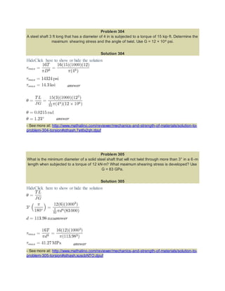
  • 1. Problem 304 A steel shaft 3 ft long that has a diameter of 4 in is subjected to a torque of 15 kip·ft. Determine the maximum shearing stress and the angle of twist. Use G = 12 × 106 psi. Solution 304 HideClick here to show or hide the solution answer answer - See more at: http://www.mathalino.com/reviewer/mechanics-and-strength-of-materials/solution-to-problem- 304-torsion#sthash.7et6x2qh.dpuf Problem 305 What is the minimum diameter of a solid steel shaft that will not twist through more than 3° in a 6 -m length when subjected to a torque of 12 kN·m? What maximum shearing stress is developed? Use G = 83 GPa. Solution 305 HideClick here to show or hide the solution answer answer - See more at: http://www.mathalino.com/reviewer/mechanics-and-strength-of-materials/solution-to-problem- 305-torsion#sthash.xuscbNTO.dpuf
  • 2. Problem 306 A steel marine propeller shaft 14 in. in diameter and 18 ft long is used to transmit 5000 hp at 189 rpm. If G = 12 × 106 psi, determine the maximum shearing stress. Solution 306 HideClick here to show or hide the solution answer - See more at: http://www.mathalino.com/reviewer/mechanics-and-strength-of-materials/solution-to-problem- 306-torsion#sthash.gWIzxTKY.dpuf Problem 307 A solid steel shaft 5 m long is stressed at 80 MPa when twisted through 4°. Using G = 83 GPa, compute the shaft diameter. What power can be transmitted by the shaft at 20 Hz? Solution 307 HideClick here to show or hide the solution answer
  • 3. answer - See more at: http://www.mathalino.com/reviewer/mechanics-and-strength-of-materials/solution-to-problem- 307-torsion#sthash.fLkmgj20.dpuf Problem 308 A 2-in-diameter steel shaft rotates at 240 rpm. If the shearing stress is limited to 12 ksi, determine the maximum horsepower that can be transmitted. Solution 308 HideClick here to show or hide the solution answer - See more at: http://www.mathalino.com/reviewer/mechanics-and-strength-of-materials/solution-to-problem- 308-torsion#sthash.uqfrC5Oy.dpuf Problem 309 A steel propeller shaft is to transmit 4.5 MW at 3 Hz without exceeding a shearing stress of 50 MPa or twisting through more than 1° in a length of 26 diameters. Compute the proper diameter if G = 83 GPa. Solution 309 HideClick here to show or hide the solution
  • 4. Based on maximum allowable shearing stress: Based on maximum allowable angle of twist: Use the larger diameter, thus, d = 352 mm. answer - See more at: http://www.mathalino.com/reviewer/mechanics-and-strength-of-materials/solution-to-problem- 309-torsion#sthash.o0ktq1Mp.dpuf Problem 310 Show that the hollow circular shaft whose inner diameter is half the outer diameter has a torsional strength equal to 15/16 of that of a solid shaft of the same outside diameter. Solution 310 HideClick here to show or hide the solution Hollow circular shaft: Solid circular shaft:
  • 5. (okay!) - See more at: http://www.mathalino.com/reviewer/mechanics-and-strength-of-materials/solution-to-problem- 310-torsion#sthash.5JhAkxrA.dpuf Problem 311 An aluminum shaft with a constant diameter of 50 mm is loaded by torques applied to gears attached to it as shown in Fig. P-311. Using G = 28 GPa, determine the relative angle of twist of gear D relative to gear A. Solution 311 HideClick here to show or hide the solution Rotation of D relative to A:
  • 6. answer - See more at: http://www.mathalino.com/reviewer/mechanics-and-strength-of-materials/solution-to-problem- 311-torsion#sthash.m2vqDvnC.dpuf Problem 312 A flexible shaft consists of a 0.20-in-diameter steel wire encased in a stationary tube that fits closely enough to impose a frictional torque of 0.50 lb·in/in. Determine the maximum length of the shaft if the shearing stress is not to exceed 20 ksi. What will be the angular deformation of one end relative to the other end? G = 12 × 106 psi. Solution 312 HideClick here to show or hide the solution If θ = dθ, T = 0.5L and L = dL answer
  • 7. - See more at: http://www.mathalino.com/reviewer/mechanics-and-strength-of-materials/solution-to-problem- 312-torsion#sthash.IMY9oI8U.dpuf Problem 313 Determine the maximum torque that can be applied to a hollow circular steel shaft of 100 -mm outside diameter and an 80-mm inside diameter without exceeding a shearing stress of 60 MPa or a twist of 0.5 deg/m. Use G = 83 GPa. Solution 313 HideClick here to show or hide the solution Based on maximum allowable shearing stress: Based on maximum allowable angle of twist: Use the smaller torque, T = 4 198.28 N·m. answer - See more at: http://www.mathalino.com/reviewer/mechanics-and-strength-of-materials/solution-to-problem- 313-torsion#sthash.glMBmcRC.dpuf Problem 314 The steel shaft shown in Fig. P-314 rotates at 4 Hz with 35 kW taken off at A, 20 kW removed at B, and 55 kW applied at C. Using G = 83 GPa, find the maximum shearing stress and the angle of rotation of gear A relative to gear C.
  • 8. Solution 314 HideClick here to show or hide the solution Relative to C: ∴ answer
  • 9. answer - See more at: http://www.mathalino.com/reviewer/mechanics-and-strength-of-materials/solution-to-problem- 314-torsion#sthash.GZRzQW6J.dpuf Problem 315 A 5-m steel shaft rotating at 2 Hz has 70 kW applied at a gear that is 2 m from the left end where 20 kW are removed. At the right end, 30 kW are removed and another 20 kW leaves the shaft at 1.5 m from the right end. (a) Find the uniform shaft diameter so that the shearing stress will not exceed 60 MPa. (b) If a uniform shaft diameter of 100 mm is specified, determine the angle by which one end of the shaft lags behind the other end. Use G = 83 GPa. Solution 315 HideClick here to show or hide the solution
  • 10. Part (a) For AB For BC For CD Use d = 69.6 mm answer Part (b) answer - See more at: http://www.mathalino.com/reviewer/mechanics-and-strength-of-materials/solution-to-problem- 315-torsion#sthash.fBhMEs49.dpuf Problem 316 A compound shaft consisting of a steel segment and an aluminum segment is acted upon by two torques as shown in Fig. P-316. Determine the maximum permissible value of T subject to the following conditions: τst ≤ 83 MPa, τal ≤ 55 MPa, and the angle of rotation of the free end is limited to 6°. For steel, G = 83 GPa and for aluminum, G = 28 GPa.
  • 11. Solution 316 HideClick here to show or hide the solution Based on maximum shearing stress, τmax = 16T / πd3: Steel Aluminum Based on maximum angle of twist, θmax = 6°:
  • 12. Use the least value of T. Thus, T = 679.04 N·m answer - See more at: http://www.mathalino.com/reviewer/mechanics-and-strength-of-materials/solution-to-problem- 316-torsion#sthash.AgjqEvBj.dpuf Problem 317 A hollow bronze shaft of 3 in. outer diameter and 2 in. inner diameter is slipped over a solid steel shaft 2 in. in diameter and of the same length as the hollow shaft. The two shafts are then fastened rigidly together at their ends. For bronze, G = 6 × 10⁶ psi, and for steel, G = 12 × 106 psi. What torque can be applied to the composite shaft without exceeding a shearing stress of 8000 psi in the bronze or 12 ksi in the steel? Solution 317 HideClick here to show or hide the solution → Equation (1) Applied Torque = Resisting Torque → Equation (2) Equation (1) with Tst in terms of Tbr and Equation (2) Equation (1) with Tbr in terms of Tst and Equation (2)
  • 13. Based on hollow bronze (Tbr = 0.6701T) Based on steel core (Tst = 0.3299T): Use T = 4232.44 lb·ft. answer - See more at: http://www.mathalino.com/reviewer/mechanics-and-strength-of-materials/solution-to-problem- 317-torsion#sthash.0I4Fdv3a.dpuf Problem 318 A solid aluminum shaft 2 in. in diameter is subjected to two torques as shown in Fig. P-318. Determine the maximum shearing stress in each segment and the angle of rotation of the free end. Use G = 4 × 10⁶ psi. Solution 318 HideClick here to show or hide the solution
  • 14. For the 2-ft segment: answer For the 3-ft segment: answer Angle of twist answer - See more at: http://www.mathalino.com/reviewer/mechanics-and-strength-of-materials/solution-to-problem- 318-torsion#sthash.927Wj3R2.dpuf Problem 319 The compound shaft shown in Fig. P-319 is attached to rigid supports. For the bronze segment AB, the diameter is 75 mm, τ ≤ 60 MPa, and G = 35 GPa. For the steel segment BC, the diameter is 50 mm, τ ≤ 80 MPa, and G = 83 GPa. If a = 2 m and b = 1.5 m, compute the maximum torque T that can be applied.
  • 15. Solution 319 HideClick here to show or hide the solution → Equation (1) → Equation (2a) → Equation (2b) Based on τbr ≤ 60 MPa → Maximum allowable torque for bronze From Equation (2b)
  • 16. Based on τbr ≤ 80 MPa → Maximum allowable torque for steel From Equation (2a) From Equation (1), use Tbr = 3.142 kN·m and Tst = 1.963 kN·m answer - See more at: http://www.mathalino.com/reviewer/mechanics-and-strength-of-materials/solution-to-problem- 319-torsion#sthash.ItnLWiwi.dpuf Problem 320 In Prob. 319, determine the ratio of lengths b/a so that each material will be stressed to its permissible limit. What torque T is required? Solution 320 HideClick here to show or hide the solution From the solution of Problem 319: Maximum Tbr = 4.970 kN·m Maximum Tst = 1.963 kN·m
  • 17. answer - See more at: http://www.mathalino.com/reviewer/mechanics-and-strength-of-materials/solution-to-problem- 320-torsion#sthash.6nxUFdzn.dpuf Problem 321 A torque T is applied, as shown in Fig. P-321, to a solid shaft with built-in ends. Prove that the resisting torques at the walls are T1 = Tb/L and T2 = Ta/L. How would these values be changed if the shaft were hollow? Solution 321 HideClick here to show or hide the solution → Equation (1) → Equation (2a) → Equation (2b) Equations (1) and (2b):
  • 18. (okay!) Equations (1) and (2a): (okay!) If the shaft were hollow, Equation (1) would be the same and the equality θ1 = θ2, by direct investigation, would yield the same result in Equations (2a) and (2b). Therefore, the values of T1 and T2 are the same (no change) if the shaft were hollow. - See more at: http://www.mathalino.com/reviewer/mechanics-and-strength-of-materials/solution-to-problem- 321-torsion#sthash.MohyNe5b.dpuf Problem 322 A solid steel shaft is loaded as shown in Fig. P-322. Using G = 83 GPa, determine the required diameter of the shaft if the shearing stress is limited to 60 MPa and the angle of rotation at the free end is not to exceed 4 deg. Solution 322 HideClick here to show or hide the solution Based on maximum allowable shear:
  • 19. For the 1st segment: For the 2nd segment: Based on maximum angle of twist: Use answer - See more at: http://www.mathalino.com/reviewer/mechanics-and-strength-of-materials/solution-to-problem- 322-torsion#sthash.OWug7nMw.dpuf Problem 323 A shaft composed of segments AC, CD, and DB is fastened to rigid supports and loaded as shown in Fig. P-323. For bronze, G = 35 GPa; aluminum, G = 28 GPa, and for steel, G = 83 GPa. Determine the maximum shearing stress developed in each segment.
  • 20. Solution 323 HideClick here to show or hide the solution Stress developed in each segment with respect to TA: The rotation of B relative to A is zero.
  • 21. (okay!) answer answer answer - See more at: http://www.mathalino.com/reviewer/mechanics-and-strength-of-materials/solution-to-problem- 323-torsion#sthash.dubUyY3F.dpuf Problem 324 The compound shaft shown in Fig. P-324 is attached to rigid supports. For the bronze segment AB, the maximum shearing stress is limited to 8000 psi and for the steel segment BC, it is limited to 12 ksi. Determine the diameters of each segment so that each material will be simultaneously stressed to its permissible limit when a torque T = 12 kip·ft is applied. For bronze, G = 6 × 10⁶ psi and for steel, G = 12 × 106 psi. Solution 324 HideClick here to show or hide the solution
  • 22. For bronze: For steel: → Equation (1)
  • 23. From Equation (1) answer answer - See more at: http://www.mathalino.com/reviewer/mechanics-and-strength-of-materials/solution-to-problem- 324-torsion#sthash.74dyRe8X.dpuf Problem 325 The two steel shaft shown in Fig. P-325, each with one end built into a rigid support have flanges rigidly attached to their free ends. The shafts are to be bolted together at their flanges. However, initially there is a 6° mismatch in the location of the bolt holes as shown in the figure. Determine the maximum shearing stress in each shaft after the shafts are bolted together. Use G = 12 × 106 psi and neglect deformations of the bolts and flanges. Solution 325 HideClick here to show or hide the solution
  • 24. answer answer - See more at: http://www.mathalino.com/reviewer/mechanics-and-strength-of-materials/solution-to-problem- 325-torsion#sthash.rR8XqYaz.dpuf Problem 337 A torque of 600 N·m is applied to the rectangular section shown in Fig. P-337. Determine the wall thickness t so as not to exceed a shear stress of 80 MPa. What is the shear stress in the short sides? Neglect stress concentration at the corners. Solution 337 HideClick here to show or hide the solution Where: answer At any convenient center O within the section, the farthest side is the shorter one, thus, it is induced with the maximum allowable shear stress of 80 MPa. - See more at: http://www.mathalino.com/reviewer/mechanics-and-strength-of-materials/solution-to-problem- 337-torsion-of-thin-walled-tube#sthash.NayevjH1.dpuf
  • 25. Problem 338 A tube 0.10 in. thick has an elliptical shape shown in Fig. P-338. What torque will cause a shearing stress of 8000 psi? Solution 338 HideClick here to show or hide the solution Where: answer - See more at: http://www.mathalino.com/reviewer/mechanics-and-strength-of-materials/solution-to-problem- 338-torsion-of-thin-walled-tube#sthash.DlHovKOp.dpuf
  • 26. Problem 339 A torque of 450 lb·ft is applied to the square section shown in Fig. P-339. Determine the smallest permissible dimension a if the shearing stress is limited to 6000 psi. Problem 339 HideClick here to show or hide the solution Where: answer - See more at: http://www.mathalino.com/reviewer/mechanics-and-strength-of-materials/solution-to-problem- 339-torsion-of-thin-walled-tube#sthash.KMfdcv2w.dpuf Problem 340 A tube 2 mm thick has the shape shown in Fig. P-340. Find the shearing stress caused by a torque of 600 N·m.
  • 27. Solution 340 HideClick here to show or hide the solution Where: answer - See more at: http://www.mathalino.com/reviewer/mechanics-and-strength-of-materials/solution-to-problem- 340-torsion-of-thin-walled-tube#sthash.vlSNH5IP.dpuf Problem 341 Derive the torsion formula τ = Tρ / J for a solid circular section by assuming the section is composed of a series of concentric thin circular tubes. Assume that the shearing stress at any point is proportional to its radial distance. Solution 341 HideClick here to show or hide the solution Where:
  • 28. and it follows that (okay!) - See more at: http://www.mathalino.com/reviewer/mechanics-and-strength-of-materials/solution-to-problem- 341-torsion-of-thin-walled-tube#sthash.DtqK6K15.dpuf