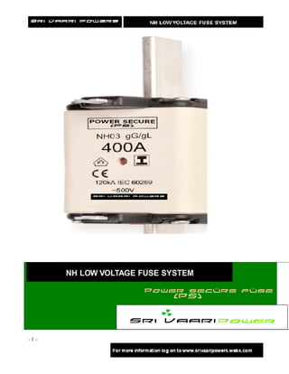
NH fuse system for Industrial application in wide range like 400, 500 & 690 V with Indicator functional as per BS & IEC Standards in brabd name of Power Secure (PS).
2. Power secure (PS) fuse brand a division of Sri Vaari Power Industries, is
the leading source of Circuit protection solutions in the global marketplace. Sri Vaari Power
products are manufactures under use of around the world and meet agency requirements and
international standards: IEC, VDE, DIN, UL, BS and others.
Sri Vaari Power manufacture over 10,000 part numbers covering extensive circuit protection
solutions for a wide range of applications: residential, industrial, motor protection, power
conversion, distribution, telecommunications, electronics and automotive.
Sri Vaari Power has been a leading in the design, development and manufacture of High
Voltage & low voltage fuse links and their associated accessories for more than five years and
has supplied fuse links to more than 50 countries worldwide.
The Sri Vaari Power team of specialist engineers plays a leading role in international
standardization of low voltage fuse links, offering comprehensive advice on selection and
applications.
With a continual commitment to meet our customers’ needs with innovative high quality
products with ISO 9002 “approval systems”, Sri Vaari Power is the suppliers’ choice for low
voltage circuit protection solutions.
Today, the majority of NH fuse like according to DIN 43 620 & IEC 60269 have single / Duel
indicator system. The most common most common type has the Indicator located on top end
plate of fuse link. In most cases that is used for Visual Indication, although it can also be used
to operate a micro switch where remote indication is required. The second type indicator is
located in the center of ceramic body of fuse link.
NH Fuse type Indicator system fuse link from Power Secure (PS) brand from Sri Vaari Powers
incorporates Top/Center Indicator system into a single ceramic fuse link body. All user benefits
from reliable and effective NH – Fuse Link compliments by a Proven Single/Duel Indication
system irrespective of whether the fuse is suitable in a fuse base, fuse switch disconnector and
Vertical fuse rail and regarding of various applications.
Fuse range is available at 400 Vac, 500 Vac & 690 Vac for ratings from 6 to 630 Amps. The
standard industrial design incorpates aluminium , copper with Isolation & Non – Isolation
extraction tag. The intrreputing ratings 100 kA at 400 Vac & 120 kA at 500 Vac.
-2-
3. NH Fuse Links Application
Introduction
The Sri Vaari Powers ® NH fuse link range uses the latest technology to provide class leading
fuse link performance and reliable indication. With a unique patented Single/Dual indicator
design capable of operating a micro switch for remote fuse indication, Powers Secure (PS)
provides one of the most reliable solutions available. The range is fully compliant with IEC 60269
standards and complies with the dimensional requirements of DIN 43620 for ease of use.
In order to help select the correct product for an application, Powers Secure (PS) provides the
following application notes.
Selecting the Correct Product
Before making a fuse link selection the following information should be known about the system
or circuit to be protected.
Type of Application (Cable Protection / Motor Protection)
For general applications or cable protection, the standard gG (general purpose) NH fuse link
should be considered. For Motor protection applications, the aM (motor protection) NH fuse link
should be considered. Motor Protection (aM) fuse links have partial range breaking ability and
cannot clear low overload faults. Should only be applied to circuits also protected by a motor
protection relay or where only high short-circuit faults could occur.
Please note that misapplication of a fuse link can be dangerous, consult Powers Secure (PS) if
there is any doubt over fuse link selection.
System Voltage
Powers Secure (PS) NH fuse links are available in three voltage ratings, 400V, 500V and 690V.
These are maximum voltage ratings and should not be used where the system voltage could
exceed the fuse link’s maximum rating.
Full Load Current
In accordance with IEC standards, Powers Secure (PS) NH fuse links are tested to carry full
load current. The rated current of a fuse link should be equal or greater than the operational
current of the circuit and equal or smaller than he continuous current carrying capacity of the
conductor. The standard gG (general purpose) NH fuse link with a conventional fusing current of
1.6 times rated current will give assured cable protection against the effects of overcurrent.
-3-
4. Non-Fault Overload Currents (motor inrush currents etc)
To prevent nuisance operation of the fuse link, the fuse link rating selected for the application
should take into account any non-fault overload currents. Please refer to the time-current curves
in the catalogue.
Possible Fault Conditions and Maximum Short-Circuit Current
This information is essential in order to select the fuse link that would provide the best possible
protection under all fault conditions. Powers Secure (PS) NH fuse links have a maximum
breaking capacity of 100 & 120kA and should never be used on a system where the maximum
short-circuit current exceeds this level. Please refer to the time-current curve in the catalogue.
NH Fuse Links Application
Time-Current Curves
The time-current curve is probably the most useful piece of all fuse link data available. It allows
you to determine how quickly the fuse link will operate under fault conditions and which fuse link
will not operate under non-fault overload currents.
To use the curve simply plot the prospective Root Mean Square (RMS) fault current along the X
axis and draw a line vertically upwards from this point. Where this point intersects the fuse curve
line, plot a line across to the Y axis for the relevant rating. The Y axis shows the nominal
operating time for the fuse in seconds. Hence, it shows how quickly the fuse link will operate
under different fault currents.
The graph can be used to check if a fuse link can withstand an overload condition that is not
considered to be a fault such as a direct-on-line (DOL) motor start. For example, if a motor starts
and the inrush current is six times the full load current for 10 seconds, the exact point can be
plotted onto the time-current curve. Any fuse link line lying to the right of this point will withstand
the motor start current (allowing for a +/-10% tolerance on each fuse link curve). If the fuse link
curve falls to the left of this point, then the fuse link will not withstand the motor start current and
will inadvertently operate when the motor is started.
In summary, the rule for time-current curves is that any point on or to the right of a fuse link
curve would indicate the fuse link has operated in the given time. Any point to the left of the
curve would indicate the fuse link has not operated.
-4-
5. B
Fuse rating
Cut off current Peak Peak let through current
Peak RMS let through Current
RMS Prospective fault current
A RMS Prospective fault current
Cut-Off Curves
The graph consists of an A-B line running diagonally from bottom left to top right, see drawing
below. This is known as he none current-limiting line. Branching from this A-B line you can see
each individual fuse link rating line running iagonally left to right. o read the graph, plot the RMS
prospective fault current along the X axis. If this point only ntersects the A-B line then the
prospective fault current is too low to benefit from the current-limiting effect of the fuse ink.
However, if this point intersects the relevant fuse link line, plot a line across to the Y axis. This
point on the Y axis shows the peak asymmetrical let-through current the fuse link will allow to
pass before operating. The peak asymmetrical let-through current is the absolute worst case
peak current the fuse link will allow to pass through, taking nto account the DC offset seen under
short-circuit conditions and low power factor.
The RMS let-through current is read from the graph sing the same procedure above. Instead of
plotting he point of intersection with the fuse link current limiting line over to the Y axis, it should
only be plotted as far as the A-B line. At this point, a line can be drawn back down to the X axis
to show a RMS symmetrical value of let-through current. This is known as the “up, over and
down method”.
-5-
6. NH Fuse Links Application
I2t Values
I2t values are measured at the time of testing the fuse link at their rated breaking capacity and
voltage. I2t is effectively the amount of heating energy the fuse link will allow to pass during fault
clearing at high short-circuit faults. I2t values relevant for short-circuit faults cannot be calculated
from the time-current or cut-off curves. The published I2t figures always show two values, pre-
arcing/total clearing and are representative of the area under the first half cycle of the fault
current. I2t values give a good representation of the speed of operation of a fuse link. A small I2t
value would indicate a very fast-acting fuse link whereas a large I2t value would indicate a fairly
slow operating fuse link.
In all cases the total clearing I2t value of the fuse link must be smaller than the I2t value of the
device to be protected in order for the fuse link to provide adequate protection against short-
circuit faults. For fuse link discrimination (see definition of discrimination below) in distribution
systems, the total clearing I2t value of the fuse link downstream should be less than the pre-
arcing I2t value of the fuse link upstream. This ensures the smaller fuse link, in the system
operates well before the larger upstream fuse link.
NH Discrimination
Power Secure (PS) ® NH fuse links are easy to use on distribution networks where
discrimination between large and small fuse links are required. This can be achieved by applying
a discrimination factor of 1 to 1.6 without the need to check the fuse link data. For example, by
using a 100A fuse link downstream from the main 160A fuse link, in the event of a fault
condition, the smaller 100A fuse link is sure to operate before the 160A fuse link, ensuring
discrimination.
DC Applications
Power Secure (PS) NH fuse links can be used on DC applications. In all cases the fuse links can
be used at half of their AC rating with a time constant of no more than 10mS. The time
constant is the rate of rise of fault current and should be as close to a 50Hz AC half cycle as
possible.
Power Loss
Every effort is made to ensure the power loss of the fuse link is kept to a minimum. Cooper
Bussmann provides fuse links with some of the lowest power losses in the industry. Power loss
of the fuse link is given off as heat and this should be taken into account when fitting fuse links
into unventilated areas. It is preferable that a fuse link has good airflow around the body of the
fuse link to ensure cool running and prevent nuisance operation of the fuse link due to thermal
stresses.
-6-
7. NH Dual Indicator System Catalogue
• The pre-arcing value is the area under the first half cycle of fault current showing on
the
graph in yellow to the point just before an arc occurs within the fuse link. This is due to
the element material being vaporized by the very high short-circuit current.
• The total clearing I2t is the yellow and green area under the first half cycle from the
start
of the short-circuit current flow to the point where the fuse link has become an
insulator, completely isolating the flow of current. The diagram here shows a
representation of I2t during a half cycle of fault current.
Time in Seconds
Potentional Fault Current
A – Pre Arc I2T
A Current in amps B – Total clearing I2T.
B
NH Industrial application Low Voltage
Fuse System
• High breaking capacity
• 400 Vac, 500Vac & 690 Vac
• Indication provide
• DIN 43 620 & IEC 60269 (Standard Dimensions)
-7-
9. VOLTAGE Amps
CLASS 2 4 6 10 16 25 32 40 50 63 80 100 125 160 200 250 315 3 4 5 6 8 1 1
5 0 0 3 0 0 2
SIZE 5 0 0 0 0 0
0
5
0
000
00
1
(C)
1
400 gG (S)
2
(C)
2
(S)
3
(C)
3
(S)
000
00
1
(C)
gG / 1
500 aM (S)
2
(C)
2
(S)
3
(C)
3
(S)
000
00
1
(C)
1
gG / (S)
2
690 aM (C)
2
(S)
3
(C)
3
(S)
C – COMPACT SIZE
S – STANDARD SIZE
-9-
10. KEY LIST FOR ORDERING
FUSE LINK MODLE TYPE NH
CURRENT RATING 100
UTILIZATION CLASS G
BRAND NAME : POWER SECURE (PS) PS
FUSE BODY SIZE 01C
INSULATED METAL GRIPPING LUGS
(OTHER OPTIONAL) I I
COMPLETE PART NUMBER NH 100 G PS 01C I
Intuitive Part Number:
Power secure fuse logical part numbering system provides simple identification of fuse
link current, utilization class, size and voltage, ensuring easy identification on site
reducing replacement time and improving network productivity.
- 10 -
11. NH Fuse Size 000 – 2 to 100 Amps
List of part numbers
Rating Rating
Size Class Voltage Current Part number Pack
(Vac) (Amps) Qty
2 NH 2 G PS 000 I - 400
4 NH 4 G PS 000 I - 400
6 NH 6 G PS 000 I - 400
10 NH 10 G PS 000 I - 400
16 NH 16 G PS 000 I - 400
000 gG/gL 400 25 NH 25 G PS 000 I - 400
32 NH 32 G PS 000 I - 400
40 NH 40 G PS 000 I - 400
50 NH 50 G PS 000 I - 400
63 NH 63 G PS 000 I - 400
80 NH 80 G PS 000 I - 400
2 NH 2 G PS 000 I - 500
4 NH 4 G PS 000 I - 500
6 NH 6 G PS 000 I - 500
10 NH 10 G PS 000 I - 500
16 NH 16 G PS 000 I - 500
500 25 NH 25 G PS 000 I - 500
000 gG/gL 32 NH 32 G PS 000 I - 500
40 NH 40 G PS 000 I - 500
50 NH 50 G PS 000 I - 500
63 NH 63 G PS 000 I - 500
80 NH 80 G PS 000 I - 500
100 NH100G PS 000 I - 500
2 NH 2 G PS 000 I - 690
4 NH 4 G PS 000 I - 690
6 NH 6 G PS 000 I - 690
10 NH 10 G PS 000 I - 690
000 gG 690 16 NH 16 G PS 000 I - 690
25 NH 25 G PS 000 I - 690
32 NH 32 G PS 000 I - 690
40 NH 40 G PS 000 I - 690
50 NH 50 G PS 000 I - 690
Size a a1 a2 a3 b c1 c2 d e1 e2 e3 e4 f
000 78.5 ± 2 54 45 50 15 35 10 2 ± 0.5 40 20 16 6 8
- 11 -
12. NH Fuse Size 000 – 2 to 50 Amps (Motor protection)
Rating Rating
Size Class Voltage Current Part number Pack
(Vac) (Amps) Qty
2 NH 2 AM PS 000 I - 690
4 NH 4 AM PS 000 I - 690
6 NH 6 AM PS 000 I - 690
10 NH 10 AM PS 000 I - 690
16 NH 16 AM PS 000 I - 400
000 aM 690 25 NH 25 AM PS 000 I - 690
32 NH 32 AM PS 000 I - 690
40 NH 40 AM PS 000 I - 690
50 NH 40 AM PS 000 I - 690
NH Fuse Size 00 (compact) – 63 to 100 Amps
Rating Rating
Size Class Voltage Current Part number Pack
(Vac) (Amps) Qty
63 NH 63 G PS 00 C - 400
00 gG/gL 80 NH 80 G PS 00 C - 400
(compact) 400 100 NH 100 G PS 00 C - 400
00 63 NH 63 G PS 00 C - 500
80 NH 80 G PS 00 C - 500
(compact) gG/gL 500 100 NH 100 G PS 00 C - 500
00 63 NH 63 G PS 00 C - 690
(compact) gG/gL 690 80 NH 80 G PS 00 C - 690
Size a a1 a2 a3 b c1 c2 d e1 e2 e3 e4 f
00 78.5 ± 2 54 45 50 15 35 12 2 ± 0.5 48 30 24 6 15
(compact)
NH Fuse Size 00 – 63 to 100 Amps (Motor protection)
List of part numbers
Rating Rating
Size Class Voltage Current Part number Pack
(Vac) (Amps) Qty
63 NH 2 AM PS 00 C - 500
aM 80 NH 4 AM PS 00 C - 500
00 500 100 NH 6 AM PS 00 C - 500
- 12 -
13. NH Fuse Size 0 (standard) – 32 to 100 Amps
List of part numbers
Rating Rating
Size Class Voltage Current Part number Pack
(Vac) (Amps) Qty
32 NH 32 G PS 00 S - 500
40 NH 40 G PS 00 S - 500
0 gG/gL 50 NH 50 G PS 00 S - 500
(standard) 500 63 NH 63 G PS 00 S - 500
80 NH 80 G PS 00 S - 500
100 NH 100 G PS 00 S - 500
32 NH 32 G PS 00 S - 690
40 NH 40 G PS 00 S - 690
0 gG/gL 50 NH 50 G PS 00 S - 690
(standard) 690 63 NH 63 G PS 00 S - 690
80 NH 80 G PS 00 S - 690
100 NH 100 G PS 00 S - 690
NH Fuse Size 0 (standard) – 6 to 100 Amps (Motor protection)
List of part numbers
` Rating Rating
Size Class Voltage Current Part number Pack
(Vac) (Amps) Qty
25 NH 25 AM PS 0 C - 500
0 aM 32 NH 32 AM PS 0 C - 500
(standard) 500 40 NH 40 AM PS 0 C - 500
50 NH 50 AM PS 0 C - 500
63 NH 63 AM PS 0 C - 500
80 NH 80 AM PS 0 C - 500
100 NH100 AM PS 0 C - 500
4 NH 4 AM PS 0 C - 690
0 aM 6 NH 6 AM PS 0 C - 690
(standard) 690 10 NH 10 AM PS 0 C - 690
16 NH 16 AM PS 0 C - 690
Size a a1 a2 a3 b c1 c2 d e1 e2 e3 e4 f
0 124 ± 2 66 60 66 15 35 12 2.5 ± 0.5 48 30 24 6 15
(standard)
- 13 -
14. NH Fuse Size 1 (compact) – 16 to 125 Amps
List of part numbers
Rating Rating
Size Class Voltage Current Part number Pack
(Vac) (Amps) Qty
16 NH 16 G PS 1 C - 400
25 NH 25 G PS 1 C - 400
32 NH 32 G PS 1 C - 400
40 NH 40 G PS 1 C - 400
1 gG/gL 400 50 NH 50 G PS 1 C - 400
63 NH 63 G PS 1 C - 400
(compact) 80 NH 80 G PS 1 C - 400
100 NH100 G PS 1 C - 400
125 NH125 G PS 1 C - 400
16 NH 16 G PS 1 C - 500
25 NH 25 G PS 1 C - 500
32 NH 32 G PS 1 C - 500
40 NH 40 G PS 1 C - 500
1 gG/gL 50 NH 50 G PS 1 C - 500
(compact) 500 63 NH 63 G PS 1 C - 500
80 NH 80 G PS 1 C - 500
100 NH100 G PS 1 C - 500
16 NH 16 G PS 1 C - 690
25 NH 25 G PS 1 C - 690
32 NH 32 G PS 1 C - 690
1 gG/gL 40 NH 40 G PS 1 C - 690
(compact) 690 50 NH 50 G PS 1 C - 690
63 NH 63 G PS 1 C - 690
80 NH 80 G PS 1 C - 690
63 NH 63 AM PS 1 C - 500
80 NH 80 AM PS 1 C - 500
1 aM 500 100 NH 100 AM PS 1 C - 500
(compact) 125 NH 125 AM PS 1 C - 500
Size a a1 a2 a3 b c1 c2 d e1 e2 e3 e4 f
1 136 ± 2 76 62 68 15 40 12 2.5 ± 0.5 48 30 24 6 15
(compact)
- 14 -
15. NH Fuse Size 1 (standard) – 125 to 200 Amps
List of part numbers
Rating Rating
Size Class Voltage Current Part number Pack
(Vac) (Amps) Qty
125 NH125 G PS 1 S - 400
1 gG/gL 160 NH160 G PS 1 S - 400
(standard) 400 200 NH200 G PS 1 S - 400
125 NH125 G PS 1 S - 500
1 gG/gL 500 160 NH160 G PS 1 S - 500
(standard) 200 NH200 G PS 1 S - 500
100 NH100 G PS 1 S - 690
1 gG/gL 125 NH125 G PS 1 S - 690
(standard) 690 160 NH160 G PS 1 S - 690
200 NH200 G PS 1 S - 690
1 160 NH 160 AM PS 1 S - 500
200 NH 200 AM PS 1 S - 500
(standard aM 500
690 160 NH 160 AM PS 1 S - 690
NH Fuse Size 1 (standard) – 160 Amps (Motor protection)
List of part numbers
` Rating Rating
Size Class Voltage Current Part number Pack
(Vac) (Amps) Qty
1 aM 160 NH 160 AM PS 1 S - 690
(standard) 690
Size a a1 a2 a3 b c1 c2 d e1 e2 e3 e4 f
1 136 ± 2 76 62 68 20 40 12 2.5 ± 0.5 52 52 24 6 15
(standard)
- 15 -
16. NH Fuse Size 2 (compact) – 32 to 200 Amps
List of part numbers
Rating Rating
Size Class Voltage Current Part number Pack
(Vac) (Amps) Qty
32 NH 32 G PS 2 C - 400
40 NH 40 G PS 2 C - 400
50 NH 50 G PS 2 C - 400
63 NH 63 G PS 2 C - 400
2 gG/gL 400 80 NH 80 G PS 2 C - 400
100 NH100 G PS 2 C - 400
(compact) 125 NH 125G PS 2 C - 400
160 NH 160G PS 2 C - 400
200 NH 200G PS 2 C - 400
32 NH 32 G PS 2 C - 500
40 NH 40 G PS 2 C - 500
50 NH 50 G PS 2 C - 500
63 NH 63 G PS 2 C - 500
02 gG/gL 80 NH 80 G PS 2 C - 500
(compact) 500 100 NH100 G PS 2 C - 500
125 NH125 G PS 2 C - 500
160 NH160 G PS 2 C - 500
200 NH200 G PS 2 C - 500
250 NH250 G PS 2 C - 500
32 NH 32 G PS 2 C - 690
40 NH 40 G PS 2 C - 690
50 NH 50 G PS 2 C - 690
02 gG/gL 63 NH 63 G PS 2 C - 690
(compact) 690 80 NH 80 G PS 2 C - 690
100 NH100 G PS 2 C - 690
125 NH125 G PS 2 C - 690
Size a a1 a2 a3 b c1 c2 d e1 e2 e3 e4 f
2 150 ± 2 76 62 68 20 48 12 2.5 ± 0.5 52 52 24 6 15
(compact)
- 16 -
17. NH Fuse Size 2 (standard) – 250 to 400 Amps
List of part numbers
Rating Rating
Size Class Voltage Current Part number Pack
(Vac) (Amps) Qty
250 NH250 G PS 2 S - 400
315 NH315 G PS 2 S - 400
2 gG/gL 400 355 NH355 G PS 2 S - 400
(standard) 400 NH400 G PS 2 S - 400
250 NH250 G PS 2 S - 500
315 NH315 G PS 2 S - 500
2 gG/gL 355 NH355 G PS 2 S - 500
(standard) 500 400 NH400 G PS 2 S - 500
500 NH500 G PS 2 S - 500
200 NH200 G PS 2 S - 690
2 gG/gL 690 250 NH250 G PS 2 S - 690
(standard)
Size a a1 a2 a3 b c1 c2 d e1 e2 e3 e4 f
2 150 ± 2 76 62 68 25 48 12 2.5 ± 0.5 60 60 24 6 15
(standard)
NH Fuse Size 2 (standard) – 125 to 400 Amps (Motor protection)
List of part numbers
` Rating Rating
Size Class Voltage Current Part number Pack
(Vac) (Amps) Qty
2
(standard) aM 500 400 NH 400 AM PS 2 C - 500
125 NH 125 AM PS 2 C - 690
2 aM 160 NH 160 AM PS 2 C - 690
(standard) 690 200 NH 200 AM PS 2 C - 690
250 NH 250 AM PS 2 C - 690
315 NH 315 AM PS 2 C - 690
350 NH 350 AM PS 2 C - 690
- 17 -
18. NH Fuse Size 03 (compact) – 200 to 315 Amps
List of part numbers
Rating Rating
Size Class Voltage Current Part number Pack
(Vac) (Amps) Qty
200 NH200 G PS 3 C - 400
250 NH250 G PS 3 C - 400
gG/gL 315 NH315 G PS 3 C - 400
03 400 355 NH355 G PS 3 C - 400
(compact) 400 NH400 G PS 3 C - 400
250 NH250 G PS 3 C - 500
315 NH315 G PS 3 C - 500
03 gG/gL 355 NH355 G PS 3 C - 500
(compact) 500 400 NH400 G PS 3 C - 500
500 NH500 G PS 3 C - 500
250 NH250 G PS 3 C - 690
03 gG/gL 690
315 NH315 G PS 3 C - 690
(compact)
Size a a1 a2 a3 b c1 c2 d e1 e2 e3 e4 f
03 150 ± 2 76 62 68 32 61 12 2.5 ± 0.5 60 60 24 6 15
(compact)
- 18 -
19. NH Fuse Size 3 (standard) – 400 to 1000 Amps
List of part numbers
Rating Rating
Size Class Voltage Current Part number Pack
(Vac) (Amps) Qty
400 NH400 G PS 3 S - 400
3 gG/gL 500 NH500 G PS 3 S - 400
(standard) 400 630 NH630 G PS 3 S - 400
500 NH500 G PS 3 S - 500
gG/gL 500 630 NH630 G PS 3 S - 500
3 800 NH800 G PS 3 S - 500
(standard) 1000 NH1000 G PS 3 S - 500
250 NH250 G PS 3 S - 690
3 gG/gL 315 NH315 G PS 3 S - 690
(standard) 690 355 NH355 G PS 3 S - 690
400 NH400 G PS 3 S - 690
Size a a1 a2 a3 b c1 c2 d e1 e2 e3 e4 f
3 150 ± 2 76 62 68 32 61 12 3 ± 0.5 60 60 24 6 18
(standard)
NH Fuse Size 3 (standard) – 300 to 630 Amps (Motor protection)
List of part numbers
Rating Rating
Size Class Voltage Current Part number Pack
(Vac) (Amps) Qty
3
(standard) aM 500 630 NH 630 AM PS 3 S - 500
315 NH 315 AM PS 3 S - 690
3 aM 355 NH 355 AM PS 3 S - 690
(standard) 690 400 NH 400 AM PS 3 S - 690
500 NH 500 AM PS 3 S - 690
- 19 -