1. GRAVITY THICKENER
(SEDIMENTATION)
Thickener
The process by which biosolids are condensed to produce a concentrated solids product
and a relatively solids-free supernatant. Separation of suspended solid particles from a liquid
stream by gravity settling. The primary purpose of thickening is to increase the solids
concentration of the feed stream. Used at most wastewater treatment plants, economic measure,
to reduce the volume of sludge. It reduces the volume of residuals, improves operation, and
reduces costs for subsequent storage, processing, transfer, end use, or disposal.
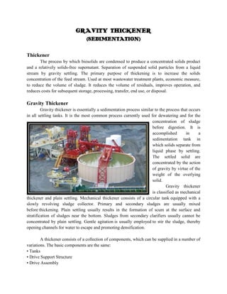
Gravity Thickener
Gravity thickener is essentially a sedimentation process similar to the process that occurs
in all settling tanks. It is the most common process currently used for dewatering and for the
concentration of sludge
before digestion. It is
accomplished
in
a
sedimentation tank in
which solids separate from
liquid phase by settling.
The settled solid are
concentrated by the action
of gravity by virtue of the
weight of the overlying
solid.
Gravity thickener
is classified as mechanical
thickener and plain settling. Mechanical thickener consists of a circular tank equipped with a
slowly revolving sludge collector. Primary and secondary sludges are usually mixed
before thickening. Plain settling usually results in the formation of scum at the surface and
stratification of sludges near the bottom. Sludges from secondary clarifiers usually cannot be
concentrated by plain settling. Gentle agitation is usually employed to stir the sludge, thereby
opening channels for water to escape and promoting densification.
A thickener consists of a collection of components, which can be supplied in a number of
variations. The basic components are the same:
• Tanks
• Drive Support Structure
• Drive Assembly
2. • Rake mechanism
• Feed Well
• Overflow Arrangement
• Underflow Arrangement
Tanks
Tanks or Basins are constructed of such material as steel, concrete, wood, compacted
earth,
plastic sheeting, and soil cement. The selection of the materials of construction is based on cost,
availability, topography, water table, ground condition, climate, operating temperature and
chemical corrosion resistance. Typically, industrial tanks up to 100 ft. in diameter are made of
steel.
Drive Support Structure
Bridge supported thickeners are common in diameters of 30m, the maximum being 45m.
They offer the following advantages over other thickeners:
• Ability to transfer loads to the tank periphery
• Ability to give a denser and more consistent underflow concentration with a single
draws off point
• A less complicated lifting device;
• Fewer structure members subject to mud accumulation;
• Access to the drive from both ends of the bridge; and
• Lower cost for units smaller than 30m in diameters.
Drive Assembly
The drive assembly is the key component of a thickener. The drive typically provides a
torque measurement that is indicated on the mechanism and may be transmitted to a remote
indicator. If the torque becomes excessive, it can automatically activate such safeguards against
structural damage as sounding an alarm, raising the rakes, and stopping the drive. Drives may be
mechanical or hydraulic.
The drive assembly provides:
● The force to move the rakes through the thickened pulp and move settled solids
to the point of discharge.
● The support mechanism which permits it to rotate.
● Adequate reserve capacity to withstand upsets and temporary overloads.
● A reliable control which protects the mechanism from the damage when a
major overload
3. Rake Mechanism
Aids in thickening the pulp by disrupting bridged floccules, permitting trapped fluid to
escape and allowing the floccules to become more consolidated. Rake mechanisms are designed
for specific application, usually having two long rakes with an option for two short rake arms.
Assists in moving the settled solids to the point of discharge.
Feedwell
An element of most sedimentation units, introduces the feeds with a minimum of
turbulence, promoting fast settling of the particles an minimizing short circuiting toward the
overflow point. A pipe or launder supported on or from the bridge transports the feed to the
feedwell.
To avoid excess velocity, an open launder normally has a slope no greater than 2/100.
Pulp should enter the launder, suspended from the bridge, at a velocity that prevents sanding at
the inlet. The
standard feed well for conventional thickeners is designed for a maximum nominal flow velocity
of 1.5 m/min.
High turbidity caused by the depth of the feed well. When overflow clarity is important
or the solids gravity is close to the liquid specific gravity, deep feed wells of large diameter are
used. Shallow feed wells may be used when overflow clarity is not important, the overflow rate
is low, and or the solids density is appreciably greater than water.
Overflow Launder
Clarified effluent typically is removed in a peripheral launder located inside or outside
the tank.
The effluent enters the launder by overflowing a V-notch or level flat weir. Uneven overflow
rates caused by wind blowing across the liquid surface in large thickeners can be better
controlled when V-notch weirs are used. The hydraulic capacity of a launder must be sufficient
to prevent flooding, which can cause short-circuiting of the feed and deterioration of overflow
density.
Deflector Cone
The Deflector Cone must be designed to remove solids, without plugging upsets, at the
maximum rate at which they will enter the thickener. Provisions must be made to unplug or to
bypass plugged piping so that solids can always be removed from the thickener to preclude their
filling the thickener and stalling the mechanism. Underflow recycle back to the feed well is used
in some applications to aid in flocculation of the unit during periods when the feed is reduced or
interrupted.
4. OPERATION:
First, the feed will enter to the feedwell, as it moves down to the feedwell flocculant is
injected so that as it moves down to the feedwell, flocculation and deaeration occur. Flocculant
causes fine particles to bind together and settled rapidly. The flocculant feed will go down to the
rake arms. The rake arm rotates slowly with the scraper blades on the bottom to push the solids
in the thickener to the deflector cone. The deflector cone is the cone shaped discharged located in
the center of the thickener. Once the solids enter the deflector cone, they are removed by pumps,
pumping the concentrated solid underflow to a conditioning tank. The clear water overflows at
the top of the thickener which channels the clear water to the overflow discharged. The overflow
is pumped from the thickener.