Reduced Axial Movement Error In a Torque-Sensing System - Hong Wan, Michael L. Freeman, Chuck von Beck

An improved torque sensing arrangement including a magnetoelastic ring on a rotatable shaft, along with two or more magnetic bands magnetized in opposite directions to produce at least two magnetic fields. Alternatively, the rotatable shaft could be magnetized into bands, eliminating the need for a magnetoelastic ring. The magnetic field sensors are positioned next to, but not contacting, the bands, and can be used to measure the field strength, which can be converted to torque. The sensors are preferable positioned to either side of the peak axial magnetic field strength areas of the bands, one offset from the center of one band in a first direction and the other offset from the center of the other band in a second direction opposite the first direction, thereby limiting the average change in the reading when the fields move under the shaft. A patent by inventors Hong Wan, Michael L. Freeman, and Chuck von Beck.

Recomendados
Mais conteúdo relacionado
Mais procurados
Mais procurados (9)
Destaque
Destaque (16)
Semelhante a Reduced Axial Movement Error In a Torque-Sensing System - Hong Wan, Michael L. Freeman, Chuck von Beck
Semelhante a Reduced Axial Movement Error In a Torque-Sensing System - Hong Wan, Michael L. Freeman, Chuck von Beck (20)
Mais de Chuck von Beck
Último
Último (20)
Reduced Axial Movement Error In a Torque-Sensing System - Hong Wan, Michael L. Freeman, Chuck von Beck
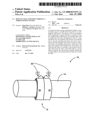
- 1. US 20060137473A1 (12) Patent Application Publication (10) Pub. No.: US 2006/0137473 A1 (19) United States Wan et al. (43) Pub. Date: Jun. 29, 2006 (54) REDUCED AXIAL MOVEMENT ERROR IN A TORQUE-SENSING SYSTEM (75) Inventors: Hong Wan, Plymouth, MN (US); Michael L. Freeman, Woodbury, MN (US); Chuck H. Von Beck, Mesa, AZ (Us) Correspondence Address: HONEYWELL INTERNATIONAL INC. 101 COLUMBIA ROAD P 0 BOX 2245 MORRISTOWN, NJ 07962-2245 (US) (73) Assignee: Honeywell International Inc., Morris toWn, NJ (21) Appl. No.: 11/023,075 (22) Filed: Dec. 27, 2004 30 12 Publication Classi?cation (51) Int. Cl. G01L 3/10 (2006.01) (52) Us. or. ........................................................73/862.331 (57) ABSTRACT An improved torque sensing arrangement includes a mag netoelastic ring on a rotatable shaft, along With tWo or more magnetic ?eld sensors. The ring has at least tWo magnetic bands magnetized in opposite directions to produce at least tWo magnetic ?elds. Alternatively, the rotatable shaft could be magnetized into bands, eliminating the need for a mag netoelastic ring. The magnetic ?eld sensors are positioned next to, but not contacting, the bands, and can be used to measure the ?eld strength, Which can be converted to torque. The sensors are preferably positioned to either side of the peak axial magnetic ?eld strength areas of the bands, one offset from the center of one band in a ?rst direction and the other offset from the center of the other band in a second direction opposite the ?rst direction, thereby limiting the average change in the reading When the ?elds move under the shaft. 10 14
- 2. Patent Application Publication Jun. 29, 2006 Sheet 1 0f 4 US 2006/0137473 A1 Fig. 1 (PriorArt)
- 3. Patent Application Publication Jun. 29, 2006 Sheet 2 of 4 US 2006/0137473 A1 Figure 1A (Prior Art) ........---._-.-.-.....-....-.--'-...----.> Figure 2 (Prior Art) H
- 4. Patent Application Publication Jun. 29, 2006 Sheet 3 0f 4 US 2006/0137473 A1 Fig. 3 30
- 5. Patent Application Publication Jun. 29, 2006 Sheet 4 0f 4 US 2006/0137473 A1 Figure 3A 31 32 H1 H2 Figure 4 31 32 <-'-------------
- 6. US 2006/0137473 A1 REDUCED AXIAL MOVEMENT ERROR IN A TORQUE-SENSING SYSTEM GOVERNMENT RIGHTS [0001] The United States Government has acquired cer tain rights in this invention pursuant to Contract No. DMHl0-03-9-000l awarded by the US. Department of the Army. BACKGROUND OF THE INVENTION [0002] [0003] This invention relates to the ?eld ofusing magnetic sensors to measure torque applied to a rotatable shaft. More particularly, the invention relates to the particular placement of magnetic torque sensors in relation to magnetic ?eld bands to reduce the axial movement error in a torque system. [0004] 2. Description of the Related Art [0005] In control of systems having rotatable drive shafts, torque and speed are the fundamental parameters of interest. The sensing and measurement of torque in an accurate, reliable, and inexpensive manner has been a primary objec tive of Workers for several decades. Examples of applica tions in Which inexpensive torque sensing devices are used include electric poWer steering systems, rotating shafts in machinery, and others. In such environments, the torque sensing devices are typically required to make loW-error continuous torque measurements over extended time peri ods, despite severe operating conditions. [0006] FIGS. 1 and 1A shoW a typical system for mea suring the torque applied to a rotatable shaft using non contact magnetic ?eld sensors. The sensors are positioned approximately directly over the peak axial strength area of each band of magnetic ?cld. However, the shaft may have axial movement due to its ?oating design or the force applied. This con?guration is very susceptible to any axial, or left and right, physical movement of the shaft. Since the sum of the sensor readings indicates the amount of torque measured, ifthe ?elds change at the sensor locations, due to movement by the shaft or ring, then both sensors Will be at a point of loWer axial ?eld, as shoWn in FIG. 2. The signal becomes Weaker and is interpreted as a loss of torque, When the actual ?eld and torque is unchanged. This causes a greater tendency for error in the torque reading. 1. Field of the Invention [0007] Accordingly, it is desirable to create a more accu rate con?guration for the magnetic sensors to reduce the torque measurement error due to the physical axial move ment of the shaft in the system. SUMMARY OF THE INVENTION [0008] The present invention meets shortcomings of the other torque sensing devices by arranging the magnetic torque sensors in a manner that minimiZes the amount of error in the torque reading. [0009] A magnetoelastic ring is press-?t onto a rotatable shaft to Which a torque may be applied. The ring has a cylindrical shape With tWo magnetic bands that are magne tiZed in opposite directions. Alternatively, the rotatable shaft could be magnetiZed into bands, eliminating the need for a magnetoelastic ring. Each band has a peak magnetic ?eld strength along the axial direction near its center. Magnetic Jun. 29, 2006 sensors, Which measure the ?eld strength in the axial direc tion to determine torque, are positioned next to, but not contacting, the bands. The sensors are positioned to either side of the peak axial ?eld strength areas of the bands, one offset from the center of one band in a ?rst direction and the other offset from the center of the other band in a second direction opposite the ?rst direction, thereby limiting the average change in the reading When the shaft moves in relation to the sensors. Upon axial movement of the shaft (magneto-elastic bands), one sensor measures a decrease in ?eld strength and the other measures an increase. The tWo ?eld strength measurements are combined and averaged to indicate the torque being applied to the shaft. Since one sensor reading is increasing and the other is decreasing due to axial movement of the shaft (but actual torque remains constant), the total error from the axial movement is less than typical torque sensing arrangements, resulting in a more accurate system. [0010] Additionally, ifthe sensors are positioned at slopes of the ?elds that are chosen in such a Way that the same amount of increase or decrease occurs When the position of shaft (bands) moves, then the torque reading is essentially immune to the axial movement of the shaft. BRIEF DESCRIPTION OF THE DRAWINGS [0011] FIG. 1 is a simpli?ed pictorial representation of a conventional sensor arrangement. [0012] FIG. 1A is a schematic representation of a con ventional sensor arrangement. [0013] FIG. 2 is a schematic representation of the con ventional sensor arrangement shoWn in FIG. 1A after under going axial movement. [0014] FIG. 3 is a simpli?ed pictorial representation ofthe sensor arrangement of the present invention. [0015] FIG. 3A is a schematic representation ofthe sensor arrangement of the present invention. [0016] FIG. 4 is a schematic representation of the sensor arrangement shoWn in FIG. 3A after undergoing axial movement. DETAILED DESCRIPTION OF PRESENTLY PREFERRED EMBODIMENTS [0017] As shoWn in FIGS. 3 and 3A, an improved sensor arrangement 10 includes a magnetoelastic ring 12 press-?t onto a rotatable shaft 14 to Which a torque may be applied. The ring 12 generally has a cylindrical shape With tWo magnetic bands 20 that are magnetiZed in opposite direc tions, producing magnetic ?elds H1 and H2. Alternatively, the rotatable shaft 14 could be magnetiZed into bands, eliminating the need for a magnetoelastic ring. Magnetic ?eld sensors 30 positioned next to, but not contacting, the bands 20, can be used to measure the ?eld strength along the axial direction, Which can be converted to torque. The sensors 30 are positioned to either side ofthe peak axial ?eld strength areas of the bands 20 so that When the magnetic ?elds H1 and H2 move (due to movement of the shaft 14 or ring 12), the average change in the reading is limited. One sensor, S1, has sensitivity in the direction of arroW 31 and is offset from the center of one band in a ?rst direction, and the other sensor, S2, has sensitivity in the direction of arroW
- 7. US 2006/0137473 A1 32 and is offset from the center ofthe other band in a second direction opposite the ?rst direction. [0018] If no torque is applied, no ?eld is detected outside the ring 12. When torque is applied, the magnetization ofthe ring 12 is reoriented and provides a magnetic ?eld outside the ring 12. The axial component of the magnetic ?eld has a maximum value near the center of each band, but since the tWo bands 20 provide opposite directions for the ?eld, the tWo sensors 30 that read the signal from the tWo bands 20 can be used to cancel the unWanted stray ?eld. This com mon-mode rejection enables a measurement of ?eld strength that is proportional to only the applied torque. [0019] Upon any physical axial movement ofthe shaft 14, and consequently the bands 20, the sensors S1 and S2 change locations relative to the shaft 14, and therefore measure di?ferent magnetic ?elds from the shaft 14 (bands 20). S1 measures an increase (or decrease) in ?eld strength and S2 measures a decrease (or increase). The tWo ?eld strength measurements are combined and averaged to indi cate the torque being applied to the shaft 14. Since one reading is increasing and the other is decreasing due to the axial movement of the shaft 14 (but actual torque remains constant), the total error is less than typical torque sensing arrangements, resulting in a more accurate system. [0020] Additionally, if the sensors 30 are positioned at slopes of the ?elds H1 and H2 that are chosen in such a Way that the same amount of increase or decrease occurs at any particular moment, then the torque reading is essentially immune to the axial movement. [0021] While certain features and embodiments of the present invention have been described in detail herein, it is to be understood that the invention encompasses all modi ?cations and enhancements Within the scope and spirit ofthe folloWing claims. 1. A magnetic torque sensing system for providing a reading indicative of the torque applied to a member about an axially extending axis of a rotatable shaft, the system comprising: a magnetoelastic ring positioned on the rotatable shaft and having ?rst and second magnetic ?eld bands, each producing a magnetic ?eld With a peak ?eld strength near the center of the band When torque is applied; and ?rst and second magnetic sensors operable to measure the magnetic ?elds of the bands in the ring; Wherein the ?rst sensor is positioned to one side of the center of the ?rst band and the second sensor is positioned to the other side of the center of the second band, thereby minimizing error in the sensed torque. 2. The system of claim 1 Wherein the ?rst sensor is offset from the center of the ?rst band in a ?rst direction. 3. The system of claim 1 Wherein the second sensor is offset from the center of the second band in a second direction, Wherein the second direction is opposite the ?rst direction. 4. The system of claim 1 Wherein the bands are magne tiZed in opposite directions. 5. The system ofclaim 1 Wherein the ring has a cylindrical shape and is press-?t onto the shaft. 6. A method for reducing the axial movement error in a torque system comprising a ring press-?t onto a shaft, the Jun. 29, 2006 ring including a ?rst and a second magnetic ?eld band, the bands having a peak ?eld strength in the center of each band, a ?rst sensor, and a second sensor, the method comprising: positioning the ?rst sensor offset from the center of the ?rst band in a ?rst direction; positioning the second sensor offset from the center ofthe second band in a second direction, Wherein the second direction is opposite the ?rst direction; measuring the magnetic ?eld of each ofthe bands With its respective sensor; determining a total magnetic ?eld from the measured magnetic ?elds of the ?rst and second bands; and converting the total magnetic ?eld into torque to obtain an initial torque for the system. 7. The method of claim 6, further comprising: measuring the magnetic ?eld of each of the bands after axial movement of the ring has occurred; determining a total magnetic ?eld from the measured magnetic ?elds of the ?rst and second bands after axial movement of the ring has occurred; and converting the total magnetic ?eld into torque to obtain a ?nal torque for the system, the ?nal total torque being approximately equal to the initial torque. 8. A magnetic torque sensing system for providing a reading indicative of the torque applied to a member about an axially extending axis of a rotatable shaft, the system comprising: a magnetoelastic ring press-?t onto the shaft; the ring having a cylindrical shape With ?rst and second magnetic ?eld bands magnetiZed in opposite directions; the magnetic ?eld bands each having a peak ?eld strength near the center of the band; and ?rst and second magnetic sensors operable to measure the magnetic ?elds of the bands in the ring; Wherein the ?rst sensor is positioned to one side of the center of the band and the second sensor is positioned to the other side of the center of the band to minimiZe the error in the torque reading. 9. The system of claim 8 Wherein the ?rst sensor is offset from the center of the ?rst band in a ?rst direction. 10. The system of claim 8 Wherein the second sensor is offset from the center of the second band in a second direction, Wherein the second direction is opposite the ?rst direction. 11. A magnetic torque sensing system for providing a reading indicative of the torque applied to a member about an axially extending axis of a rotatable shaft, the system comprising: the rotatable shaft having ?rst and second magnetic ?eld bands, each producing a magnetic ?eld With a peak ?eld strength near the center of the band When torque is applied; and ?rst and second magnetic sensors operable to measure the magnetic ?elds of the bands;
- 8. US 2006/0137473 A1 wherein the ?rst sensor is positioned to one side of the center of the ?rst band and the second sensor is positioned to the other side of the center of the second hand, thereby minimizing error in the sensed torque When the shaft moves in an axial direction. 12. The system of claim 11 Wherein the ?rst sensor is o?‘set from the center of the ?rst band in a ?rst direction. Jun. 29, 2006 13. The system of claim 11 Wherein the second sensor is o?‘set from the center of the second hand in a second direction, Wherein the second direction is opposite the ?rst direction. 14. The system of claim 11 Wherein the bands are mag netiZed in opposite directions. * * * * *