SlideShare uma empresa Scribd logo
1 de 142
Baixar para ler offline
IBM Software Group                                                                                                                    Foreword

The file "Deskbook Rel311.pdf" is the latest version of the Rational Harmony for Systems Engineering Deskbook Release 3.1 (“Deskbook”), released
May 28, 2010.

July 2010
The Deskbook is written for the practitioner. Screenshots, notes and best practice tips are added to the workflow descriptions. The brief introductions
are minimal rather than narrative. The Deskbook is not intended to replace training for the IBM Rational Rhapsody component of the IBM Rational
Workbench for Systems and Sofware Enigineering; it is intended to supplement it. It is assumed that the reader is familiar with UML/SysML and the
IBM Rational Rhapsody component of the IBM Rational Workbench for Systems and Software Engineering.

Systems Engineering Best Practices with the Rational
Permission to use, copy, and distribute, this Deskbook, is granted; provided, however, that the use, copy, and distribution of the Deskbook is made in
whole and not in part.
Workbench for Systems and Software Engineering
THIS DESKBOOK IS PROVIDED "AS IS." IBM MAKE NO REPRESENTATIONS OR WARRANTIES, EXPRESS OR IMPLIED, INCLUDING, BUT
NOT LIMITED TO, WARRANTIES OF MERCHANTABILITY, OR FITNESS FOR A PARTICULAR PURPOSE.

IBM WILL NOT BE LIABLE FOR ANY DIRECT, INDIRECT, SPECIAL, OR CONSEQUENTIAL DAMAGES ARISING OUT OF ANY USE OF THE
DESKBOOK OR THE PERFORMANCE OR IMPLEMENTATION OF THE CONTENTS OF THE DESKBOOK..


Deskbook
The directory "Deskbook Rel.3.1 Requirements and Models" contains the requirements specification for the Security System example and snapshots
of the models generated with Rhapsody.    Release 3.1.1
Copyright IBM Corporation 2006, 2010
IBM Corporation
Software Group
Route 100
Model-Based Systems Engineering with Rational Rhapsody and
Somers, NY 10589
U.S.A.
Rational Harmony for Systems Engineering
Licensed Materials - Property of IBM Corporation
U.S. Government Users Restricted Rights: Use, duplication or disclosure restricted by GSA ADP Schedule Contract with IBM Corp.

IBM, the IBM logo, Rational, the Rational logo, Telelogic, the Telelogic logo and other IBM products and services are trademarks of the International
Business Machines Corporation, in the United States, other countries or both.


Hans-Peter Hoffmann, may be trademarks or service marks of others.
Other company, product, or service names
                                         Ph.D.
Chief Systems Methodologist found at ibm.com/software/rational
The Rational Software home page on the Internet can be

The IBM home page on the Internet can be found at ibm.com
hoffmape@us.ibm.com


                                                                                                                                © 2010 IBM Corporation
The file "Deskbook Rel311.pdf" is the latest version of the “Systems Engineering Best Practices with the Rational Workbench for Systems and
Software Engineering Deskbook Release 3.1.1” (“Deskbook”), released July 1, 2010.

The Deskbook is written for the practitioner. Screenshots, notes and best practice tips are added to the workflow descriptions. The brief introductions
are minimal rather than narrative. The Deskbook is not intended to replace IBM Rational Rhapsody training; it is intended to supplement it. It is
assumed that the reader is familiar with UML/SysML and the IBM Rational Rhapsody tool.

Permission to use, copy, and distribute, this Deskbook, is granted; provided, however, that the use, copy, and distribution of the Deskbook is made in
whole and not in part.

THIS DESKBOOK IS PROVIDED "AS IS." IBM MAKE NO REPRESENTATIONS OR WARRANTIES, EXPRESS OR IMPLIED, INCLUDING, BUT
NOT LIMITED TO, WARRANTIES OF MERCHANTABILITY, OR FITNESS FOR A PARTICULAR PURPOSE.

IBM WILL NOT BE LIABLE FOR ANY DIRECT, INDIRECT, SPECIAL, OR CONSEQUENTIAL DAMAGES ARISING OUT OF ANY USE OF THE
DESKBOOK OR THE PERFORMANCE OR IMPLEMENTATION OF THE CONTENTS OF THE DESKBOOK..

The directory "Deskbook Rel.3.1.1 Requirements and Models" contains the requirements specification for the Security System example and
snapshots of the models generated with Rhapsody.

Copyright IBM Corporation 2006, 2010
IBM Corporation
Software Group
Route 100
Somers, NY 10589
U.S.A.

Licensed Materials - Property of IBM Corporation
U.S. Government Users Restricted Rights: Use, duplication or disclosure restricted by GSA ADP Schedule Contract with IBM Corp.

IBM, the IBM logo, Rational, the Rational logo, Telelogic, the Telelogic logo and other IBM products and services are trademarks of the International
Business Machines Corporation, in the United States, other countries or both.

Other company, product, or service names may be trademarks or service marks of others.

The Rational Software home page on the Internet can be found at ibm.com/software/rational

The IBM home page on the Internet can be found at ibm.com
Foreword

                                                               Foreword to the Deskbook Release 3.0

                                                               Here it is – the long awaited next iteration. I completely restructured
                                                               the Deskbook, focusing more on the methododical part of Harmony for
                                                               Systems Engineering and its support in Rhapsody by means of the
                                                               Rhapsody SE-Toolkit. This release also extends the previous scope.
                                                               It now addresses Requirements Elaboration and Traceability as well
                                                               as Architectural Analysis through Trade Studies.

                                                               I want to thank two colleagues who deserve special mentions with
                                                               regard to their contributions to this release: Andy Lapping and Dr.
                                                               Graham Bleakley. Andy - the “Wizard Guru” – is the author of the
                                                               Rhapsody-SE-Toolkit. Whenever I came up with an idea, how the SE
                                                               workflow could be automated, the next day I got the wizard-based
                                                               solution. Graham is the specialist for Architectural Analysis. The
                                                               chapter on how to perform a trade study is based on his input. Here
                                                               again, Andy automated it by respective wizards.

                                                               Any feed-back for the next iteration (release) is appreciated.

                                                               Andover, 06-01-09


                                                               Foreword to the Deskbook Release 2.0
                                                               The systems engineering process is iterative. There is no reason why
                                                               this should not be applicable also to this Deskbook. Meanwhile,
                                                               numerous companies started to apply the Harmony for Systems
                                                               Engineering process using the Deskbook as a general guideline.

                                                               This revision takes into consideration the feed-back that I got from “the
                                                               field”. Especially with regard to the use case analysis, I realized that
                                                               the approach needed to consider the needs of projects with a large
                                                               numbers of use cases. Nothing changed with regard to the workflow.
                                                               What changed, is the project structure. The new project structure
                                                               supports team collaboration. Each use case now may be elaborated
                                                               separately and then – iteratively - merged to a common system model.
                                                               The outlined process (Harmony for Systems Engineering) is tool
                                                               independent.

                                                               Andover, 10-12-06
                 The Author - by J. Rick White


© Copyright IBM Corporation 2006, 2010. All Rights Reserved.
Table of Contents


Table of Contents

1     INTRODUCTION                                         1
    1.1      Scope.................................................................................................................................................................................................................... 1
    1.2      Document Overview ............................................................................................................................................................................................. 1
2     FUNDAMENTALS OF HARMONY FOR SYSTEMS ENGINEERING...............................................................................................................................2
    2.1      Rational Integrated Systems / Embedded Software Development Process Harmony ........................................................................................ 2
    2.2      Model-based Systems Engineering Process........................................................................................................................................................ 4
          2.2.1 Requirements Analysis.................................................................................................................................................................................. 5
          2.2.2 System Functional Analysis .......................................................................................................................................................................... 6
          2.2.3 Design Synthesis......................................................................................................................................................................................... 10
          2.2.3.1   Architectural Analysis (Trade Study).................................................................................................................................................... 11
          2.2.3.2   Architectural Design ............................................................................................................................................................................. 14
          2.2.3.3   Detailed Architectural Design............................................................................................................................................................... 16
          2.2.4 Systems Engineering Hand-Off................................................................................................................................................................... 18
    2.3      Essential SysML Artifacts of Model-based Systems Engineering ...................................................................................................................... 19
          2.3.1 Requirements Diagram ............................................................................................................................................................................... 20
          2.3.2 Structure Diagrams...................................................................................................................................................................................... 20
          2.3.2.1    Block Definition Diagram...................................................................................................................................................................... 20
          2.3.2.2    Internal Block Diagram......................................................................................................................................................................... 20
          2.3.2.3    Parametric Diagram ............................................................................................................................................................................. 22
          2.3.3 Behavior Diagrams ...................................................................................................................................................................................... 22
          2.3.3.1    Use Case Diagram ............................................................................................................................................................................... 23
          2.3.3.2    Activity Diagram ................................................................................................................................................................................... 23
          2.3.3.3    Sequence Diagram .............................................................................................................................................................................. 24
          2.3.3.4    Statechart Diagram .............................................................................................................................................................................. 24
          2.3.4 Artifact Relationships at the Requirements Analysis / System Functional Analysis Level.......................................................................... 25
    2.4      Service Request-Driven Modeling Approach ..................................................................................................................................................... 26
3     RHAPSODY PROJECT STRUCTURE............................................................................................................................................................................27
    3.1      Project Structure Overview................................................................................................................................................................................. 27
    3.2      Requirements Analysis Package........................................................................................................................................................................ 28
    3.3      Functional Analysis Package.............................................................................................................................................................................. 29
    3.4      Design Synthesis Package................................................................................................................................................................................. 30


ii | Systems Engineering Best Practices Deskbook                                                                                     © Copyright IBM Corporation 2006, 2010. All Rights Reserved.
Table of Contents

          3.4.1 Architectural Analysis Package ................................................................................................................................................................... 30
          3.4.2 Architectural Design Package ..................................................................................................................................................................... 31
    3.5      System-Level Definitions .................................................................................................................................................................................... 32
4     CASE STUDY: SECURITY SYSTEM ............................................................................................................................................................................. 33
    4.1      Getting Started.................................................................................................................................................................................................... 33
    4.2      Requirements Analysis ....................................................................................................................................................................................... 34
          4.2.1     Import of Stakeholder Requirements........................................................................................................................................................... 35
          4.2.2     Generation of System Requirements .......................................................................................................................................................... 36
          4.2.3     Linking System Requirements to Stakeholder Requirements..................................................................................................................... 38
          4.2.4     Definition of System-Level Use Cases ........................................................................................................................................................ 40
          4.2.5     Linking Requirements to Use Cases ........................................................................................................................................................... 41
    4.3      System Functional Analysis................................................................................................................................................................................ 43
          4.3.1 Uc1ControlEntry .......................................................................................................................................................................................... 44
          4.3.1.1  Project Structure of the Uc1 Model ...................................................................................................................................................... 44
          4.3.1.2  Definition of Uc1 Functional Flow......................................................................................................................................................... 45
          4.3.1.3  Definition of Uc1 Scenarios .................................................................................................................................................................. 46
          4.3.1.4  Definition of Ports and Interfaces ......................................................................................................................................................... 50
          4.3.1.5  Definition of State-based Behavior....................................................................................................................................................... 51
          4.3.1.6  Uc1 Model Verification ......................................................................................................................................................................... 53
          4.3.1.7  Linking Uc1 Block Properties to Requirements................................................................................................................................... 55
          4.3.2 Uc2ControlExit............................................................................................................................................................................................. 58
          4.3.2.1  Project Structure of the Uc2 Model ...................................................................................................................................................... 58
          4.3.2.2  Definition of Uc2 Functional Flow......................................................................................................................................................... 58
          4.3.2.3  Definition of Uc2 Scenarios .................................................................................................................................................................. 59
          4.3.2.4  Definition of Ports and Interfaces ......................................................................................................................................................... 60
          4.3.2.5  Definition of State-based Behavior....................................................................................................................................................... 60
          4.3.2.6  Uc2 Model Verification ......................................................................................................................................................................... 61
          4.3.2.7  Linking Uc2 Block Properties to Requirements................................................................................................................................... 61
          4.3.3 Merging Use Case Blocks ........................................................................................................................................................................... 62
    4.4      Design Synthesis ................................................................................................................................................................................................ 63
          4.4.1 Architectural Analysis (Trade-Off Analysis)................................................................................................................................................. 63
          4.4.1.1   Definition of Key System Functions ..................................................................................................................................................... 64
          4.4.1.2   Definition of Candidate Solutions ......................................................................................................................................................... 65
          4.4.1.3   Definition of Assessment Criteria ......................................................................................................................................................... 66
          4.4.1.4   Assigning Weights to Assessment Criteria .......................................................................................................................................... 67
          4.4.1.5   Definition of a Utility Curve for each Criterion ...................................................................................................................................... 68
          4.4.1.6   Assigning Measures of Effectiveness (MoE) to each Solution............................................................................................................. 69
          4.4.1.7   Determination of Solution ..................................................................................................................................................................... 70
          4.4.2 Architectural Design .................................................................................................................................................................................... 72

© Copyright IBM Corporation 2006, 2010. All Rights Reserved.                                                                           Systems Engineering Best Practices Deskbook | iii
Table of Contents

         4.4.2.1         Security System Decomposition .......................................................................................................................................................... 72
         4.4.2.2         Graphical Allocation of Operations....................................................................................................................................................... 74
         4.4.2.3         Formalizing the Allocation of Operations ............................................................................................................................................. 77
         4.4.2.4         Allocation of Non-functional Requirements.......................................................................................................................................... 79
         4.4.3           Detailed Architectural Design............................................................................................................................................................... 81
         4.4.3.1         Derive White-Box Sequence Diagrams ............................................................................................................................................... 82
         4.4.3.2         Definition of Ports and Interfaces ......................................................................................................................................................... 87
         4.4.3.3         Definition of State-based Behavior....................................................................................................................................................... 89
         4.4.3.4         System Architecture Model Verification .............................................................................................................................................. 93
5    HAND-OFF TO SUBSYSTEM DEVELOPMENT.............................................................................................................................................................94
6    APPENDIX                                           95
    A1      Mapping Security System Requirements to Model Artifacts .............................................................................................................................. 95
    A2      Extended Architectural Model of the Security System ....................................................................................................................................... 98
         A2.1 Extended System Architecture .................................................................................................................................................................... 99
         A2.2 Extended State-based Behavior of Subsystems...................................................................................................................................... 100
         A2.3 Verification of the Extended System Architecture Model ......................................................................................................................... 102
    A3      Modeling Guidelines ......................................................................................................................................................................................... 103
         A3.1     General Guidelines and Drawing Conventions ......................................................................................................................................... 103
         A3.2     Use Case Diagram .................................................................................................................................................................................... 104
         A3.3     Block Definition Diagram ........................................................................................................................................................................... 105
         A3.4     Internal Block Diagram .............................................................................................................................................................................. 106
         A3.5     Activity Diagram......................................................................................................................................................................................... 108
         A3.6     Sequence Diagram.................................................................................................................................................................................... 111
         A3.7     Statechart Diagram.................................................................................................................................................................................... 113
         A3.8     Profiles....................................................................................................................................................................................................... 115
    A4      Guideline: Deriving a Statechart Diagram ....................................................................................................................................................... 116
    A5      Guideline: Logical Decomposition of a Use Case Black-Box Activity Diagram............................................................................................... 121
    A6      Rhapsody Action Language ............................................................................................................................................................................. 128
    A7      Rhapsody SE-Toolkit (Overview) ..................................................................................................................................................................... 131
7    REFERENCES                                         134


iv | Systems Engineering Best Practices Deskbook                                                                                  © Copyright IBM Corporation 2006, 2010. All Rights Reserved.
Table of Figures


Table of Figures
Fig.2-1 Rational Integrated Systems / Embedded Software Development Process Harmony.......................................................................................... 2
Fig.2-2 Model-based Systems Engineering ....................................................................................................................................................................... 4
Fig.2-3 Workflow in the Requirements Analysis Phase ..................................................................................................................................................... 5
Fig.2-4 Alternative Approaches of Building an Executable Use Case Model .................................................................................................................... 6
Fig.2-5 Derivation of a Use Case Scenario from a Use Case Black-Box Activity Diagram (Industrial Automation Use Case)........................................ 8
Fig.2-6 Workflow of the Use Case Model Rainy Day Analysis .......................................................................................................................................... 9
Fig.2-7 Workflow in the System Functional Analysis Phase .............................................................................................................................................. 9
Fig.2-8 Subphases and Workflow in the Design Synthesis Phase .................................................................................................................................. 10
Fig.2-9 Workflow and Work Product ............................................................................................................................................................................... 11
Fig.2-10 Different Shapes of Utility Curves ...................................................................................................................................................................... 12
Fig.2-11 Tasks and Workproducts in the Architectural Design Phase............................................................................................................................. 14
Fig.2-12 Nested Use Case White-Box Activity Diagram .................................................................................................................................................. 14
Fig.2-13 Allocation of Operations to Subsystems (Use Case Fig.2-5) ............................................................................................................................ 15
Fig.2-14 Workflow and Workproducts in the Detailed Architectural Design Phase ......................................................................................................... 16
Fig. 2-15 Derivation of White-Box Scenarios from a Use Case White-Box Activity Diagram (ref. Fig.2-13) ................................................................... 17
Fig.2-16 Overview of UML/SysML Interrelationship......................................................................................................................................................... 19
Fig.2-17 Taxonomy of SysML Diagrams Used in Harmony for Systems Engineering .................................................................................................... 19
Fig.2-18 Requirements Diagram ...................................................................................................................................................................................... 20
Fig.2-19 Block Definition Diagram.................................................................................................................................................................................... 20
Fig.2-20 Internal Block Diagram....................................................................................................................................................................................... 20
Fig.2-21 Standard Ports ................................................................................................................................................................................................... 21
Fig.2-22 Flow Ports .......................................................................................................................................................................................................... 21
Fig.2-23 Constraint Block Definition in a Block Definition Diagram ................................................................................................................................. 22
Fig.2-24 Parametric Diagram ........................................................................................................................................................................................... 22
Fig.2-25 Use Case Diagram............................................................................................................................................................................................. 23
Fig.2-26 Activity Diagram ................................................................................................................................................................................................. 23
Fig.2-27 Sequence Diagram ............................................................................................................................................................................................ 24
Fig.2-28 Statechart Diagram ............................................................................................................................................................................................ 24
Fig.2-29 SysML Artifacts Relationship at the Requirements Analysis / System Functional Analysis Level .................................................................... 25
Fig.4-1 Requirements Analysis Workflow and its Support through the Rhapsody SE-Toolkit......................................................................................... 34
Fig.4-2 Stakeholder Requirements Specification............................................................................................................................................................. 35
Fig.4-3 System Functional Analysis Workflow and its Support through the Rhapsody SE-Toolkit ................................................................................. 43
Fig.4-4 Workflow in the Architectural Analysis Phase and its Support through the Rhapsody SE-Toolkit ...................................................................... 63

 © Copyright IBM Corporation 2006, 2010. All Rights Reserved.                                                                             Systems Engineering Best Practices Deskbook | v
Tables

Fig.4-5 Architectural Design Workflow and its Support through the Rhapsody SE-Toolkit ............................................................................................. 72
Fig.4-6 Detailed Architectural Design Workflow and its Support through the Rhapsody SE-Toolkit............................................................................... 81

Fig.A4-1     Use Case Black-Box Activity Diagram Uc2 ControlExit .................................................................................................................................. 116
Fig.A4-2     UC-Scenario Uc2_Sc1 .................................................................................................................................................................................... 116
Fig.A4-3     Uc-Scenario Uc2_Sc2 ..................................................................................................................................................................................... 116
Fig.A4-4     Wait States of Uc2_ControlExit ....................................................................................................................................................................... 117
Fig.A4-5     Action States of Uc2 ControlExit ..................................................................................................................................................................... 117
Fig.A4-6     Flat Statechart of Uc2_ControlExit .................................................................................................................................................................. 118
Fig.A4-7     Composite State ProcessingCardData............................................................................................................................................................ 119
Fig.A4-8     Composite State UnlockingAndLockingAccessPoint ...................................................................................................................................... 119
Fig.A4-9     Top-Level Statechart of Uc2_ControlExit ........................................................................................................................................................ 120

Fig.A5-1 Use Case Diagram UCD_MultiAxesSystem ................................................................................................................................................... 121
Fig.A5-2 Use Case HomingAndManualMode: Functional and State-based Behavior at the System Decomposition Level 1.................................... 122
Fig.A5-3 Reference Activity Diagram Level2_moveAxisB and Associated Derived Scenarios...................................................................................... 123
Fig.A5-4 Linking the Reference Activity Diagram ........................................................................................................................................................... 124
Fig.A5-5 Automatically generated Extended Uc1Sc1 Sequence Diagram..................................................................................................................... 124
Fig.A5-6 Linking RefAD_MoveAxisB Scenarios to Black-Box Use Case Scenario Uc1Sc1 ......................................................................................... 125
Fig.A5-7 Extended State-Based Behavior of the Use Case Block ................................................................................................................................ 126
Fig.A5-8 Animated Sequence Diagram (Extended Uc1Sc1) ......................................................................................................................................... 126
Fig.A5-9 Allocation of RefAD_MoveAxisB Operations to Subsystems in the Architectural Design Phase ................................................................... 127


Tables
Tab.A1-1 Mapping Security System Requirements to Model Artifacts ............................................................................................................................ 95
Tab.A1-2 Mapping Security System Requirements to Model Artifacts (cont’d)............................................................................................................... 96
Tab.A1-3 Mapping Security System Requirements to Model Artifacts (cont’d)............................................................................................................... 97

Tab.A3-1 Project-Specific Tags Defined in a Profile...................................................................................................................................................... 115
Tab.A3-2 Project-Specific Properties Defined in a Profile ............................................................................................................................................. 115

Tab.A7-1 Rhapsody SE-Toolkit Features ...................................................................................................................................................................... 131
Tab.A7-2 Rhapsody SE-Toolkit Features cont’d............................................................................................................................................................ 132


vi | Systems Engineering Best Practices Deskbook                                                                             © Copyright IBM Corporation 2006, 2010. All Rights Reserved.
Introduction


1 Introduction
                                                                            •   Section 3 describes the project structure that should be followed
1.1 Scope                                                                       when the Rhapsody tool is used in a model-based systems
                                                                                engineering project.
Meanwhile, many books and articles have been published about                •   Section 4 details a case study of the Harmony for Systems
SysML, the standardized language for model-based systems                        Engineering workflow using the Rhapsody tool. The chosen
engineering [1]. But in most cases, the question of how to apply it in          example is a Security System. The workflow starts with the import
an integrated systems and software development process has not                  of stakeholder requirements into Rhapsody and ends with the
been addressed. This deskbook tries to close the gap. Based on the              definition of an executable system architecture model.        The
tool independent Rational® Integrated Systems/Embedded Software                 workflow is application oriented and focuses on the usage of the
Development Process Harmony™ it provides systems engineers with a               Rhapsody SE-Toolkit.
step-by step guide on using the SysML in a way that allows a                •   Section 5 addresses the handoff to the subsequent subsystem
seamless transition to the subsequent system development.                       (SecSysController) development.
In this deskbook the chosen tool is the Rational® systems and
software design tool Rhapsody® Release 7.5 .                                Also provided are several appendices, including
                                                                            • the documentation of the Extended System Architecture Model of
The deskbook is written for the practitioner. Screenshots, notes, and          the Security System which takes into consideration the inclusion of
best practice tips are added to the workflow descriptions. The brief           COTS components,
introductions are minimal rather than narrative.
                                                                            • a chapter about modeling/style guidelines regarding the usage of
                                                                               the various SysML diagrams in model-based systems engineering
The deskbook does not replace the Rhapsody training documentation.
It rather is intended to supplement it. It is assumed, that the reader is   • a guideline how to derive a statechart diagram from the information
familiar with the UML/SysML and the Rhapsody tool.                             captured in an activity diagram and associated sequence diagrams,
                                                                            • a guideline how to logically decompose a use case black-box
1.2 Document Overview                                                          activity diagram,
                                                                            • a quick reference guide to the Rhapsody Action Language,
The deskbook is divided into 5 sections:                                    • an overview of the Rhapsody SE-Toolkit features that are applied in
                                                                               the case study, and
• Section 1 describes the scope and structure of this book.
                                                                            • a set of references.
• Section 2 introduces the basic concepts of Harmony for Systems
   Engineering. It starts with an overview of how the systems
                                                                             Included to this deskbook is a volume containing
   engineering part of the integrated systems/embedded software
   development process Harmony fits into the model-driven                   •    the Security System stakeholder requirements,
   development lifecycle. Then, the task flow and the associated            •    for each of the SE phases the incrementally extended Rhapsody
   work products in the different systems engineering phases are                 model database:
   detailed. With regard to modeling, this section also provides an              - SecSys_RA (Requirements Analysis),
   overview of SysML artifacts that are considered essential for                 - SecSys_FA (System Functional Analysis),
   model-based systems engineering, followed by an introduction to               - SecSys_AA (Architectural Analysis),
   the service request driven modeling approach.                                 - SecSys_AD (Architectural Design/Detailed Architectural Design)
                                                                             • the Extended System Architecture Model (SecSys_EAD).


© Copyright IBM Corporation 2006, 2010. All Rights Reserved.                             Systems Engineering Best Practices Deskbook | 1
Fundamentals of Harmony for Systems Engineering


2 Fundamentals of Harmony for Systems Engineering

2.1 Rational Integrated Systems / Embedded Software Development Process Harmony
Fig.2-1 shows the Rational Integrated Systems / Embedded Software                           The Harmony process consists of two closely coupled sub-processes
Development Process Harmony by means of the classic “V” diagram.
                                                                                            - Harmony for Systems Engineering and
The left leg of the “V” describes the top-down design flow, while the
                                                                                            - Harmony for Embedded Real Time Development
right hand side shows the bottom-up integration phases from unit test
to the final system acceptance. Using the notation of statecharts, the                      The systems engineering workflow is iterative with incremental cycles
impact of a change request on the workflow is visualized by the “high-                      through the phases requirements analysis, system functional analysis
level interrupt”. Whenever a change request occurs, the process will                        and design synthesis. The increments are use case based.
restart at the requirements analysis phase.

                                                                           Change Request


                                           Stakeholder                             Harmony™ for
                                          Requirements                             Systems
                                                                                   Engineering
                                                                                                                                     System
                                                                                                                                     Validation
                                                                           Scenarios (ConOps)
                           Requirements Models,       Requirements                                                                   Plan                          System


                                                                                                  Model / Requirements Repository
                         System Use Cases Model         Analysis                                                                                                 Acceptance
                                                                                        Test
                                          Executable                               Scenarios
                                                          System Functional
                                    Use Case Model(s)         Analysis
                                                                                                                                    System
                                                                                                                                    Verification
                             Architectural Analysis Model(s),                                                                       Plan             (Sub-)System
                                 System Architecture Model      Design Synthesis
                                                                                                                                                   Integration & Test
                                                                                                                                    Component
                                                                                                                                    Verification                   Harmony™ for
                                                         System
                                                                                                                                    Procedure
                                                     Architecture                                                                                                  Embedded RT
                                                        Baseline             SW                                                                 Module             Development
                                                                      Analysis & Design                                                    Integration & Test
                                                        Software
                                                  Implementation
                                                          Model                        SW Implementation
                                                                                          & Unit Test


                               Fig.2-1 Rational Integrated Systems / Embedded Software Development Process Harmony

2 | Systems Engineering Best Practices Deskbook                                                                                     © Copyright IBM Corporation 2006, 2010. All Rights Reserved.
Fundamentals of Harmony for Systems Engineering

The software engineering workflow is characterized by the iterative       The system architecture model captures the allocation of the system
incremental cycles through the software analysis and design phase,        operations to the system architecture that was elaborated in the
the implementation phase, and the different levels of integration and     previous architectural analysis phase.       The correctness and
testing.                                                                  completeness of the system architecture model is verified through
Regarding the systems engineering and implementation iterations, it       model execution. Once the model is verified, the architectural design
should be noted, that the analysis iterations continue through            may be analyzed with regard to performance and safety requirements.
implementation and testing, thus providing something demonstrable         The analysis may include Failure Modes Effects Analysis (FMEA), and
with each iteration.                                                      Mission Criticality Analysis.

It is important to note the creation and reuse of requirements related    The baselined system architecture model defines the hand-off to the
test scenarios all along the top-down design path. These scenarios        subsequent HW/SW development.
are also used to assist the bottom-up integration and test phases and,
in the case of system changes, regression test cycles.                    Model-driven software development is supported by the Software
                                                                          Implementation Model. This model is the basis for - either manual or
The Harmony process supports Model-Driven Development (MDD). In           automatic - code generation [5,6].
a model-driven development, the model is the central work product of
the development processes, encompassing both analysis and design.         An essential element of the model-driven development process is the
Each development phase is supported by a specific type of model.          Model/Requirements Repository.       It contains the configuration
                                                                          controlled knowledge of the system under development, i.e.
Models that support the requirements analysis phase are                   -   Requirements documentation
- the Requirement Models and                                              -   Requirements traceability
- the System Use Cases Model.                                             -   Design documentation and
                                                                          -   Test definitions
A requirement model visualizes the taxonomy of requirements. The
system use cases model groups requirements into system use cases.
Neither of these models is executable.

In the system functional analysis phase the focus is on the translation
of the functional requirements into a coherent description of system
functions (operations). Each use case is translated into an executable
model and the underlying system requirements verified through model
execution.

There are two types of executable models supporting the design
synthesis phase:
- Architectural Analysis Model(s) and
- System Architecture Model
The objective of the architectural analysis model(s) - also referred to
as Trade Study Model(s) - is to elaborate an architectural concept for
the implementation of the identified operations e.g. through a
parametric analysis.


© Copyright IBM Corporation 2006, 2010. All Rights Reserved.                           Systems Engineering Best Practices Deskbook | 3
Fundamentals of Harmony for Systems Engineering


2.2 Model-based Systems Engineering Process
Key objectives of Harmony for Systems Engineering are:                                                          Fig.2-2 depicts an overview of Harmony for Systems Engineering. For
                                                                                                                each of the systems engineering phases, it shows the essential input
•   Identification and derivation of required system functions
                                                                                                                and outputs.
•   Identification of associated system modes and states
•   Allocation of the identified system functions and modes/states to a                                         The following paragraphs detail the workflow and artifacts of the
    subsystem structure                                                                                         model-based systems engineering process and outline an associated
With regard to modeling, these objectives imply a top-down approach                                             Requirements Management and Traceability (RT) concept. For a
on a high level of abstraction. The main emphasis is on the                                                     more application oriented workflow description, please refer to the
identification and allocation of a needed functionality and state-based                                         case study in Section 4.
behavior, rather than on the details of its functional behavior.

                                                                                                                          Next Iteration or
                                                                                                                          Change Request
                                                                      Stakeholder Requirements
                                                                      Stakeholder Requirements

                                                                      System Requirements                      Requirements Analysis
                                                                      System Use Cases Model                                                        SRS
                                    Model / Requirements Repository


                                                                                                                                                    (Draft)
                                                                                                                       System Use Cases

                                                                      Updated System Requirements            System Functional Analysis             System-Level
                                                                      Executable Use Case Model(s)                (Use Case-Based)                  ICD
                                                                      Use Case Scenarios (Black-Box)                                                 SRS
                                                                                                                       System Operations             (Baseline)
                                                                      Non-Functional System Requirements
                                                                                                                 Design Synthesis
                                                                      Updated System Requirements
                                                                                                                Architectural Analysis
                                                                      Architectural Analysis Model(s)               (Trade Study)
                                                                                                                      Architectural Concept
                                                                      UC Activity Diagram(s) (Black-Box)
                                                                                                                 Architectural Design
                                                                      UC Activity Diagram(s) (White-Box)
                                                                                                                      Allocated
                                                                                                                      System Operations
                                                                      UC Activity Diagram(s) (White-Box)
                                                                                                                      Detailed
                                                                      Scenarios (White-Box)                     Architectural Design
                                                                      System Architecture Model (Baseline)


                                  Links providing traceability
                                                                                                                               Logical ICDs
                                  to original requirements
                                                                                                                             HW/SW Req Specs
                                                                                                               HW/SW
                                                                                                                             incl. Test Scenarios
                                                                                                             Development


                                                                               Fig.2-2 Model-based Systems Engineering

4 | Systems Engineering Best Practices Deskbook                                                                         © Copyright IBM Corporation 2006, 2010. All Rights Reserved.
Fundamentals of Harmony for Systems Engineering


2.2.1 Requirements Analysis                                                         into required system functions (“shall” statements) and documented in
                                                                                    the Draft System Requirements Specification. For traceability, the
The objective of the requirements analysis phase is to analyze the
                                    alysis                                          identified system requirements are linked to the associated
process inputs. Stakeholder requirements are translated into system                 stakeholder requirements.
requirements that define what the system must do (functional
requirements) and how well it must perform (quality of service                      The next major step in the requirements analysis phase is the
requirements)                                                                       definition of system use cases. A use case describes a specific
                                                                                    operational aspect of the system (operational thread). It specifies the
The essential steps of the requirements analysis workflow are shown                 behavior as perceived by the actors (user) and the message flow
in Fig.2-3. It starts with the analysis and optional refinement of the              between the actors and the use case. An actor may be a person,
stakeholder requirements. Output of this phase is the Stakeholder                   another system or a piece of hardware external to the system under
                                                                                                                                             s
Requirements Specification. Essentially, stakeholder requirements                   development (SuD). A use case does not reveal or imply the system’s
focus on required capabilities. In the next step, these are transformed             internal structure (black box view).
                                                                                    Use cases may be structured hierarchically – but care should be taken
                                                                                    not to functionally decompose the use cases. Use cases are not
                                              [System Use Cases defined]            functions, they use functions. There is no “golden rule” with regard to
                                                                                    the number of use cases needed to describe a system. Experience
                                     [else]
                                                                                    shows that for large systems, typically 6 to 24 use cases may be
                            Analyze/Refine
                           Stakeholder Reqs
                                                                                    defined at the top level. At the lowest level a use case should be
                                                                                    described by at least 5, with a maximum of 25 essential use case
                                              Stakeholder
                                              Requirements                          scenarios. At this stage, emphasis is put on the identification of
                                              Specification                         “sunny day” use cases, assuming an error/fail free system behavior.
                                                                                    Exception scenarios will be identified at a later stage (=> system
                 Generate
                                              Link                                  functional analysis) through model execution. If more than 5 error/fail
                                        Stakeholder Reqs
               System Reqs
                                         to System Reqs
                                                                                    scenarios are found for a use case, they should be grouped in a
                                                                                    separate exception use case, which are then linked to the “sunny day”
                                               System                               use case via an include or extend dependency.
                                               Requirements
                                               Specification (Draft)
                                                                                    In order to assure that all functional and associated performance
                               Define                                               requirements are covered by the use cases, respective traceability
                          System Use Case
                                                                                    links need to be established.
                                Link
                      Functional / Performance                                      Once the system-level use cases are defined and the complete
                      Reqs to System Use Case                                       coverage of the functional and associated performance requirements
                                                                                    is assured, they need to be ranked according to their importance for
        [Next System Use Case]                                                      the definition of the system architecture. The order defines the
                                     [else]
                                                                                    increments of the iterative SE workflow. At the end of each iteration
                         Prioritize and Partition
                           System Use Cases
                                                                                    this ranking might need to be updated.


     Fig.2-3 Workflow in the Requirements Analysis Phase

© Copyright IBM Corporation 2006, 2010. All Rights Reserved.                                     Systems Engineering Best Practices Deskbook | 5
Fundamentals of Harmony for Systems Engineering


2.2.2 System Functional Analysis

The main emphasis of the system functional analysis phase is on the                                        Fig.2-4 details the modeling tasks and the associated work products.
transformation of the functional system requirements into a coherent                                       First, the use case model context is defined in an Internal Block
description of system functions (operations). The analysis is use                                          Diagram. Elements of this diagram are instances of SysML blocks,
case-based, i.e. each system-level use case that was identified in the                                     representing the use case and its associated actor(s). At this stage,
previous requirements analysis phase is translated into an executable                                      the blocks are empty and not linked.
model. The model and the underlying requirements then are verified
through model execution.
                                                                                   Build Executable Model of Use Case


                                                                                             Define Use Case Model Context
                                                                                               (UC Internal Block Diagram)

                                                                                                                    [Alternative 3]
                                                                                         [Alternative 1]
                                                                                                              [Alternative 2]

                                                      Define UC Scenarios                      Define UC Functional Flow              Define UC State-Based Behavior
                                                (UC Black-Box Sequence Diagrams)             (UC Black-Box Activity Diagram)               (UC Statechart Diagram)


                                                   Derive UC Functional Flow                      Derive UC Scenarios                       Derive UC Scenarios
                                                       from UC Scenarios                        from UC Functional Flow                  from UC Statechart Diagram
                                                 (UC Black-Box Activity Diagram)            (UC Black-Box Sequence Diagrams)          (UC Black-Box Sequence Diagrams)


                                                                                               Define Ports And Interfaces               Define Ports And Interfaces
                                                                                               (UC Internal Block Diagram)               (UC Internal Block Diagram)

                                      Document
                                  New / Derived Reqs                                        Derive UC State-Based Behavior
                                                                                            from UC Black-Box AD and SDs
                                                                                                (UC Statechart Diagram)


                                                                                                   Verify UC Model
                                                                                               through Model Execution

                                                                                                                    [else]

                                                                                                               [Rainy Day Analysis]
                                                                                                    Extend UC Model
                                                                                                w.r.t. Error/Fail Behavior


                                                                                      Link
                                                                           UC Block Properties to Reqs


                                                                                      Update
                                                                              Draft System Req Spec


                                          Fig.2-4 Alternative Approaches of Building an Executable Use Case Model

6 | Systems Engineering Best Practices Deskbook                                                                        © Copyright IBM Corporation 2006, 2010. All Rights Reserved.
Fundamentals of Harmony for Systems Engineering

The next step in the modeling workflow is the definition of the behavior    activity diagram (ref. Fig.2-5). Ports and interfaces of the use case
of the use case block. It is captured by means of three SysML               block are created from the sequence diagrams. Lastly, its state-based
diagrams:                                                                   behavior is captured in a statechart diagram.

- Activity Diagram,                                                         Alternative 3 starts with the definition of the use case state-based
- Sequence Diagrams, and                                                    behavior. This approach is recommended if the system under design
- Statechart Diagram.                                                       (SuD) is strongly state-based. In this case, the creation of a use case
                                                                            black-box activity diagram may even be skipped. Use case scenarios
Each diagram plays a specific role in the elaboration of the use case       then are derived as paths through the statechart diagram. From the
behavior. The activity diagram – referred to as Use Case Black-Box          sequence diagram then ports and associated interfaces are
Activity Diagram - describes the overall functional flow (storyboard) of    generated.
the use case. It groups functional requirements in actions – in
Harmony for Systems Engineering the equivalent of operations - and          It should be noted, that regardless of which approach is chosen, the
shows, how these actions/operations are linked to each other. The           most important diagram in the system functional analysis process is
sequence diagram – referred to as Use Case Black-Box Sequence               the use case block statechart diagram. It comprises the information of
Diagram - describes a specific path through the use case and defines        both the black-box sequence diagrams and the use case black-box
the interactions (messages) between the operations and the actors.          activity diagram and can be verified through model execution. The
The statechart diagram aggregates the information from the activity         use case black-box activity diagram and the associated black-box
diagram (functional flow) and the sequence diagrams (actor                  sequence diagrams will be reused further down in the design process.
interactions). It puts this information into the context of system states
                                                                            Whenever during the use case based system functional analysis new
and adds to it the system behavior due to external stimuli of different
                                                                            requirements are identified or high-level requirements are detailed by
priority.
                                                                            derived requirements, they need to be documented. Last at the end of
There is no mandate directing in which order these diagrams should          the system functional analysis phase, these additional requirements
be generated. The order may depend on the available information and         need to be approved by the stakeholders and exported to the
the modeler’s preference.        Fig.2-4 shows three alternative            requirements traceability tool.
approaches:
                                                                            The use case model is analyzed through model execution using the
                                                                            black-box use case scenarios as the basis for respective stimuli. It
Alternative 1 starts with the definition of use case scenarios.
                                                                            should be noted, that - following the previously outlined key objectives
Customers often describe sequences of required system usage (e.g.
                                                                            of this process - the primary focus is on the verification of the
Concept of Operations). Once a set of essential scenarios is
                                                                            generated sequences rather than on the validation of the underlying
captured, the identified functional flow is merged into a common
                                                                            functionality.
description in an activity diagram. Ports and interfaces are created
from the sequence diagrams (ref. section 2.4 Service Request-Driven
Modeling Approach). They define the links between the actor(s) and
the use case block in the use case model internal block diagram. The
final step in this approach is the definition of the state-based behavior
of the use case block in a statechart diagram.

Alternative 2 starts with the definition of the use case functional
flow. This is a common approach, if systems engineers have to
elaborate requirements. Typically, customers like to express their
requirements from the “big picture” point of view. Once the overall
functional flow is defined, use case scenarios are derived from the

© Copyright IBM Corporation 2006, 2010. All Rights Reserved.                             Systems Engineering Best Practices Deskbook | 7
Deskbook:  Systems Engineering Best Practices with the Rational Workbench for Systems and Software Engineering

Mais conteúdo relacionado

Mais de Bill Duncan

Red Hat Accredited Professional - Red Hat Sales Specialist Infrastructure as ...
Red Hat Accredited Professional - Red Hat Sales Specialist Infrastructure as ...Red Hat Accredited Professional - Red Hat Sales Specialist Infrastructure as ...
Red Hat Accredited Professional - Red Hat Sales Specialist Infrastructure as ...Bill Duncan
 
Ibm bluemix—from idea to application by karim abousedera
Ibm bluemix—from idea to application by karim abousederaIbm bluemix—from idea to application by karim abousedera
Ibm bluemix—from idea to application by karim abousederaBill Duncan
 
IBM Federal Systems Integrator Forum at InterConnect
IBM Federal Systems Integrator Forum at InterConnectIBM Federal Systems Integrator Forum at InterConnect
IBM Federal Systems Integrator Forum at InterConnectBill Duncan
 
Create software builds with jazz team build
Create software builds with jazz team buildCreate software builds with jazz team build
Create software builds with jazz team buildBill Duncan
 
How DOORS Helps JPL Get to Mars & Beyond
How DOORS Helps JPL Get to Mars & BeyondHow DOORS Helps JPL Get to Mars & Beyond
How DOORS Helps JPL Get to Mars & BeyondBill Duncan
 
Space Quarterly: September 2011
Space Quarterly:  September 2011Space Quarterly:  September 2011
Space Quarterly: September 2011Bill Duncan
 
Tutorial: Create a custom work item in Rational Team Concert
Tutorial: Create a custom work item in Rational Team ConcertTutorial: Create a custom work item in Rational Team Concert
Tutorial: Create a custom work item in Rational Team ConcertBill Duncan
 
How to implement access restrictions to your EA artifacts using Rational Syst...
How to implement access restrictions to your EA artifacts using Rational Syst...How to implement access restrictions to your EA artifacts using Rational Syst...
How to implement access restrictions to your EA artifacts using Rational Syst...Bill Duncan
 
Speed delivery of Android devices and applications with model-driven development
Speed delivery of Android devices and applications with model-driven developmentSpeed delivery of Android devices and applications with model-driven development
Speed delivery of Android devices and applications with model-driven developmentBill Duncan
 
Optimize load handling for high-volume tests with IBM Rational Performance Te...
Optimize load handling for high-volume tests with IBM Rational Performance Te...Optimize load handling for high-volume tests with IBM Rational Performance Te...
Optimize load handling for high-volume tests with IBM Rational Performance Te...Bill Duncan
 
Improve software development project success with better information
Improve software development project success with better informationImprove software development project success with better information
Improve software development project success with better informationBill Duncan
 
Automate document generation from SysML models with Rational Rhapsody Reporte...
Automate document generation from SysML models with Rational Rhapsody Reporte...Automate document generation from SysML models with Rational Rhapsody Reporte...
Automate document generation from SysML models with Rational Rhapsody Reporte...Bill Duncan
 
Automate document generation from sys ml models with rational rhapsody report...
Automate document generation from sys ml models with rational rhapsody report...Automate document generation from sys ml models with rational rhapsody report...
Automate document generation from sys ml models with rational rhapsody report...Bill Duncan
 
Inadequate Security Practices Expose Key NASA Network to Cyber Attack
Inadequate Security Practices Expose Key NASA Network to Cyber AttackInadequate Security Practices Expose Key NASA Network to Cyber Attack
Inadequate Security Practices Expose Key NASA Network to Cyber AttackBill Duncan
 
Integrate Rational DOORS and Rational Team Concert change management
Integrate Rational DOORS and Rational Team Concert change managementIntegrate Rational DOORS and Rational Team Concert change management
Integrate Rational DOORS and Rational Team Concert change managementBill Duncan
 
IBM Rational Harmony Deskbook rel 3.1.2
IBM Rational Harmony Deskbook rel 3.1.2IBM Rational Harmony Deskbook rel 3.1.2
IBM Rational Harmony Deskbook rel 3.1.2Bill Duncan
 
Advanced Rational Performance Tester reports
Advanced Rational Performance Tester reportsAdvanced Rational Performance Tester reports
Advanced Rational Performance Tester reportsBill Duncan
 
Developing service component architecture applications using rational applica...
Developing service component architecture applications using rational applica...Developing service component architecture applications using rational applica...
Developing service component architecture applications using rational applica...Bill Duncan
 
Managing requirements across Analysis and Design phases using System Architec...
Managing requirements across Analysis and Design phases using System Architec...Managing requirements across Analysis and Design phases using System Architec...
Managing requirements across Analysis and Design phases using System Architec...Bill Duncan
 
What's New in Rational Team Concert 3.0
What's New in Rational Team Concert 3.0What's New in Rational Team Concert 3.0
What's New in Rational Team Concert 3.0Bill Duncan
 

Mais de Bill Duncan (20)

Red Hat Accredited Professional - Red Hat Sales Specialist Infrastructure as ...
Red Hat Accredited Professional - Red Hat Sales Specialist Infrastructure as ...Red Hat Accredited Professional - Red Hat Sales Specialist Infrastructure as ...
Red Hat Accredited Professional - Red Hat Sales Specialist Infrastructure as ...
 
Ibm bluemix—from idea to application by karim abousedera
Ibm bluemix—from idea to application by karim abousederaIbm bluemix—from idea to application by karim abousedera
Ibm bluemix—from idea to application by karim abousedera
 
IBM Federal Systems Integrator Forum at InterConnect
IBM Federal Systems Integrator Forum at InterConnectIBM Federal Systems Integrator Forum at InterConnect
IBM Federal Systems Integrator Forum at InterConnect
 
Create software builds with jazz team build
Create software builds with jazz team buildCreate software builds with jazz team build
Create software builds with jazz team build
 
How DOORS Helps JPL Get to Mars & Beyond
How DOORS Helps JPL Get to Mars & BeyondHow DOORS Helps JPL Get to Mars & Beyond
How DOORS Helps JPL Get to Mars & Beyond
 
Space Quarterly: September 2011
Space Quarterly:  September 2011Space Quarterly:  September 2011
Space Quarterly: September 2011
 
Tutorial: Create a custom work item in Rational Team Concert
Tutorial: Create a custom work item in Rational Team ConcertTutorial: Create a custom work item in Rational Team Concert
Tutorial: Create a custom work item in Rational Team Concert
 
How to implement access restrictions to your EA artifacts using Rational Syst...
How to implement access restrictions to your EA artifacts using Rational Syst...How to implement access restrictions to your EA artifacts using Rational Syst...
How to implement access restrictions to your EA artifacts using Rational Syst...
 
Speed delivery of Android devices and applications with model-driven development
Speed delivery of Android devices and applications with model-driven developmentSpeed delivery of Android devices and applications with model-driven development
Speed delivery of Android devices and applications with model-driven development
 
Optimize load handling for high-volume tests with IBM Rational Performance Te...
Optimize load handling for high-volume tests with IBM Rational Performance Te...Optimize load handling for high-volume tests with IBM Rational Performance Te...
Optimize load handling for high-volume tests with IBM Rational Performance Te...
 
Improve software development project success with better information
Improve software development project success with better informationImprove software development project success with better information
Improve software development project success with better information
 
Automate document generation from SysML models with Rational Rhapsody Reporte...
Automate document generation from SysML models with Rational Rhapsody Reporte...Automate document generation from SysML models with Rational Rhapsody Reporte...
Automate document generation from SysML models with Rational Rhapsody Reporte...
 
Automate document generation from sys ml models with rational rhapsody report...
Automate document generation from sys ml models with rational rhapsody report...Automate document generation from sys ml models with rational rhapsody report...
Automate document generation from sys ml models with rational rhapsody report...
 
Inadequate Security Practices Expose Key NASA Network to Cyber Attack
Inadequate Security Practices Expose Key NASA Network to Cyber AttackInadequate Security Practices Expose Key NASA Network to Cyber Attack
Inadequate Security Practices Expose Key NASA Network to Cyber Attack
 
Integrate Rational DOORS and Rational Team Concert change management
Integrate Rational DOORS and Rational Team Concert change managementIntegrate Rational DOORS and Rational Team Concert change management
Integrate Rational DOORS and Rational Team Concert change management
 
IBM Rational Harmony Deskbook rel 3.1.2
IBM Rational Harmony Deskbook rel 3.1.2IBM Rational Harmony Deskbook rel 3.1.2
IBM Rational Harmony Deskbook rel 3.1.2
 
Advanced Rational Performance Tester reports
Advanced Rational Performance Tester reportsAdvanced Rational Performance Tester reports
Advanced Rational Performance Tester reports
 
Developing service component architecture applications using rational applica...
Developing service component architecture applications using rational applica...Developing service component architecture applications using rational applica...
Developing service component architecture applications using rational applica...
 
Managing requirements across Analysis and Design phases using System Architec...
Managing requirements across Analysis and Design phases using System Architec...Managing requirements across Analysis and Design phases using System Architec...
Managing requirements across Analysis and Design phases using System Architec...
 
What's New in Rational Team Concert 3.0
What's New in Rational Team Concert 3.0What's New in Rational Team Concert 3.0
What's New in Rational Team Concert 3.0
 

Último

Apidays Singapore 2024 - Building Digital Trust in a Digital Economy by Veron...
Apidays Singapore 2024 - Building Digital Trust in a Digital Economy by Veron...Apidays Singapore 2024 - Building Digital Trust in a Digital Economy by Veron...
Apidays Singapore 2024 - Building Digital Trust in a Digital Economy by Veron...apidays
 
IAC 2024 - IA Fast Track to Search Focused AI Solutions
IAC 2024 - IA Fast Track to Search Focused AI SolutionsIAC 2024 - IA Fast Track to Search Focused AI Solutions
IAC 2024 - IA Fast Track to Search Focused AI SolutionsEnterprise Knowledge
 
Advantages of Hiring UIUX Design Service Providers for Your Business
Advantages of Hiring UIUX Design Service Providers for Your BusinessAdvantages of Hiring UIUX Design Service Providers for Your Business
Advantages of Hiring UIUX Design Service Providers for Your BusinessPixlogix Infotech
 
Boost PC performance: How more available memory can improve productivity
Boost PC performance: How more available memory can improve productivityBoost PC performance: How more available memory can improve productivity
Boost PC performance: How more available memory can improve productivityPrincipled Technologies
 
Exploring the Future Potential of AI-Enabled Smartphone Processors
Exploring the Future Potential of AI-Enabled Smartphone ProcessorsExploring the Future Potential of AI-Enabled Smartphone Processors
Exploring the Future Potential of AI-Enabled Smartphone Processorsdebabhi2
 
The Role of Taxonomy and Ontology in Semantic Layers - Heather Hedden.pdf
The Role of Taxonomy and Ontology in Semantic Layers - Heather Hedden.pdfThe Role of Taxonomy and Ontology in Semantic Layers - Heather Hedden.pdf
The Role of Taxonomy and Ontology in Semantic Layers - Heather Hedden.pdfEnterprise Knowledge
 
Data Cloud, More than a CDP by Matt Robison
Data Cloud, More than a CDP by Matt RobisonData Cloud, More than a CDP by Matt Robison
Data Cloud, More than a CDP by Matt RobisonAnna Loughnan Colquhoun
 
From Event to Action: Accelerate Your Decision Making with Real-Time Automation
From Event to Action: Accelerate Your Decision Making with Real-Time AutomationFrom Event to Action: Accelerate Your Decision Making with Real-Time Automation
From Event to Action: Accelerate Your Decision Making with Real-Time AutomationSafe Software
 
🐬 The future of MySQL is Postgres 🐘
🐬  The future of MySQL is Postgres   🐘🐬  The future of MySQL is Postgres   🐘
🐬 The future of MySQL is Postgres 🐘RTylerCroy
 
Presentation on how to chat with PDF using ChatGPT code interpreter
Presentation on how to chat with PDF using ChatGPT code interpreterPresentation on how to chat with PDF using ChatGPT code interpreter
Presentation on how to chat with PDF using ChatGPT code interpreternaman860154
 
A Domino Admins Adventures (Engage 2024)
A Domino Admins Adventures (Engage 2024)A Domino Admins Adventures (Engage 2024)
A Domino Admins Adventures (Engage 2024)Gabriella Davis
 
EIS-Webinar-Prompt-Knowledge-Eng-2024-04-08.pptx
EIS-Webinar-Prompt-Knowledge-Eng-2024-04-08.pptxEIS-Webinar-Prompt-Knowledge-Eng-2024-04-08.pptx
EIS-Webinar-Prompt-Knowledge-Eng-2024-04-08.pptxEarley Information Science
 
Strategies for Unlocking Knowledge Management in Microsoft 365 in the Copilot...
Strategies for Unlocking Knowledge Management in Microsoft 365 in the Copilot...Strategies for Unlocking Knowledge Management in Microsoft 365 in the Copilot...
Strategies for Unlocking Knowledge Management in Microsoft 365 in the Copilot...Drew Madelung
 
Automating Google Workspace (GWS) & more with Apps Script
Automating Google Workspace (GWS) & more with Apps ScriptAutomating Google Workspace (GWS) & more with Apps Script
Automating Google Workspace (GWS) & more with Apps Scriptwesley chun
 
Scaling API-first – The story of a global engineering organization
Scaling API-first – The story of a global engineering organizationScaling API-first – The story of a global engineering organization
Scaling API-first – The story of a global engineering organizationRadu Cotescu
 
Mastering MySQL Database Architecture: Deep Dive into MySQL Shell and MySQL R...
Mastering MySQL Database Architecture: Deep Dive into MySQL Shell and MySQL R...Mastering MySQL Database Architecture: Deep Dive into MySQL Shell and MySQL R...
Mastering MySQL Database Architecture: Deep Dive into MySQL Shell and MySQL R...Miguel Araújo
 
Understanding Discord NSFW Servers A Guide for Responsible Users.pdf
Understanding Discord NSFW Servers A Guide for Responsible Users.pdfUnderstanding Discord NSFW Servers A Guide for Responsible Users.pdf
Understanding Discord NSFW Servers A Guide for Responsible Users.pdfUK Journal
 
A Year of the Servo Reboot: Where Are We Now?
A Year of the Servo Reboot: Where Are We Now?A Year of the Servo Reboot: Where Are We Now?
A Year of the Servo Reboot: Where Are We Now?Igalia
 
2024: Domino Containers - The Next Step. News from the Domino Container commu...
2024: Domino Containers - The Next Step. News from the Domino Container commu...2024: Domino Containers - The Next Step. News from the Domino Container commu...
2024: Domino Containers - The Next Step. News from the Domino Container commu...Martijn de Jong
 
How to Troubleshoot Apps for the Modern Connected Worker
How to Troubleshoot Apps for the Modern Connected WorkerHow to Troubleshoot Apps for the Modern Connected Worker
How to Troubleshoot Apps for the Modern Connected WorkerThousandEyes
 

Último (20)

Apidays Singapore 2024 - Building Digital Trust in a Digital Economy by Veron...
Apidays Singapore 2024 - Building Digital Trust in a Digital Economy by Veron...Apidays Singapore 2024 - Building Digital Trust in a Digital Economy by Veron...
Apidays Singapore 2024 - Building Digital Trust in a Digital Economy by Veron...
 
IAC 2024 - IA Fast Track to Search Focused AI Solutions
IAC 2024 - IA Fast Track to Search Focused AI SolutionsIAC 2024 - IA Fast Track to Search Focused AI Solutions
IAC 2024 - IA Fast Track to Search Focused AI Solutions
 
Advantages of Hiring UIUX Design Service Providers for Your Business
Advantages of Hiring UIUX Design Service Providers for Your BusinessAdvantages of Hiring UIUX Design Service Providers for Your Business
Advantages of Hiring UIUX Design Service Providers for Your Business
 
Boost PC performance: How more available memory can improve productivity
Boost PC performance: How more available memory can improve productivityBoost PC performance: How more available memory can improve productivity
Boost PC performance: How more available memory can improve productivity
 
Exploring the Future Potential of AI-Enabled Smartphone Processors
Exploring the Future Potential of AI-Enabled Smartphone ProcessorsExploring the Future Potential of AI-Enabled Smartphone Processors
Exploring the Future Potential of AI-Enabled Smartphone Processors
 
The Role of Taxonomy and Ontology in Semantic Layers - Heather Hedden.pdf
The Role of Taxonomy and Ontology in Semantic Layers - Heather Hedden.pdfThe Role of Taxonomy and Ontology in Semantic Layers - Heather Hedden.pdf
The Role of Taxonomy and Ontology in Semantic Layers - Heather Hedden.pdf
 
Data Cloud, More than a CDP by Matt Robison
Data Cloud, More than a CDP by Matt RobisonData Cloud, More than a CDP by Matt Robison
Data Cloud, More than a CDP by Matt Robison
 
From Event to Action: Accelerate Your Decision Making with Real-Time Automation
From Event to Action: Accelerate Your Decision Making with Real-Time AutomationFrom Event to Action: Accelerate Your Decision Making with Real-Time Automation
From Event to Action: Accelerate Your Decision Making with Real-Time Automation
 
🐬 The future of MySQL is Postgres 🐘
🐬  The future of MySQL is Postgres   🐘🐬  The future of MySQL is Postgres   🐘
🐬 The future of MySQL is Postgres 🐘
 
Presentation on how to chat with PDF using ChatGPT code interpreter
Presentation on how to chat with PDF using ChatGPT code interpreterPresentation on how to chat with PDF using ChatGPT code interpreter
Presentation on how to chat with PDF using ChatGPT code interpreter
 
A Domino Admins Adventures (Engage 2024)
A Domino Admins Adventures (Engage 2024)A Domino Admins Adventures (Engage 2024)
A Domino Admins Adventures (Engage 2024)
 
EIS-Webinar-Prompt-Knowledge-Eng-2024-04-08.pptx
EIS-Webinar-Prompt-Knowledge-Eng-2024-04-08.pptxEIS-Webinar-Prompt-Knowledge-Eng-2024-04-08.pptx
EIS-Webinar-Prompt-Knowledge-Eng-2024-04-08.pptx
 
Strategies for Unlocking Knowledge Management in Microsoft 365 in the Copilot...
Strategies for Unlocking Knowledge Management in Microsoft 365 in the Copilot...Strategies for Unlocking Knowledge Management in Microsoft 365 in the Copilot...
Strategies for Unlocking Knowledge Management in Microsoft 365 in the Copilot...
 
Automating Google Workspace (GWS) & more with Apps Script
Automating Google Workspace (GWS) & more with Apps ScriptAutomating Google Workspace (GWS) & more with Apps Script
Automating Google Workspace (GWS) & more with Apps Script
 
Scaling API-first – The story of a global engineering organization
Scaling API-first – The story of a global engineering organizationScaling API-first – The story of a global engineering organization
Scaling API-first – The story of a global engineering organization
 
Mastering MySQL Database Architecture: Deep Dive into MySQL Shell and MySQL R...
Mastering MySQL Database Architecture: Deep Dive into MySQL Shell and MySQL R...Mastering MySQL Database Architecture: Deep Dive into MySQL Shell and MySQL R...
Mastering MySQL Database Architecture: Deep Dive into MySQL Shell and MySQL R...
 
Understanding Discord NSFW Servers A Guide for Responsible Users.pdf
Understanding Discord NSFW Servers A Guide for Responsible Users.pdfUnderstanding Discord NSFW Servers A Guide for Responsible Users.pdf
Understanding Discord NSFW Servers A Guide for Responsible Users.pdf
 
A Year of the Servo Reboot: Where Are We Now?
A Year of the Servo Reboot: Where Are We Now?A Year of the Servo Reboot: Where Are We Now?
A Year of the Servo Reboot: Where Are We Now?
 
2024: Domino Containers - The Next Step. News from the Domino Container commu...
2024: Domino Containers - The Next Step. News from the Domino Container commu...2024: Domino Containers - The Next Step. News from the Domino Container commu...
2024: Domino Containers - The Next Step. News from the Domino Container commu...
 
How to Troubleshoot Apps for the Modern Connected Worker
How to Troubleshoot Apps for the Modern Connected WorkerHow to Troubleshoot Apps for the Modern Connected Worker
How to Troubleshoot Apps for the Modern Connected Worker
 

Deskbook: Systems Engineering Best Practices with the Rational Workbench for Systems and Software Engineering

  • 1. IBM Software Group Foreword The file "Deskbook Rel311.pdf" is the latest version of the Rational Harmony for Systems Engineering Deskbook Release 3.1 (“Deskbook”), released May 28, 2010. July 2010 The Deskbook is written for the practitioner. Screenshots, notes and best practice tips are added to the workflow descriptions. The brief introductions are minimal rather than narrative. The Deskbook is not intended to replace training for the IBM Rational Rhapsody component of the IBM Rational Workbench for Systems and Sofware Enigineering; it is intended to supplement it. It is assumed that the reader is familiar with UML/SysML and the IBM Rational Rhapsody component of the IBM Rational Workbench for Systems and Software Engineering. Systems Engineering Best Practices with the Rational Permission to use, copy, and distribute, this Deskbook, is granted; provided, however, that the use, copy, and distribution of the Deskbook is made in whole and not in part. Workbench for Systems and Software Engineering THIS DESKBOOK IS PROVIDED "AS IS." IBM MAKE NO REPRESENTATIONS OR WARRANTIES, EXPRESS OR IMPLIED, INCLUDING, BUT NOT LIMITED TO, WARRANTIES OF MERCHANTABILITY, OR FITNESS FOR A PARTICULAR PURPOSE. IBM WILL NOT BE LIABLE FOR ANY DIRECT, INDIRECT, SPECIAL, OR CONSEQUENTIAL DAMAGES ARISING OUT OF ANY USE OF THE DESKBOOK OR THE PERFORMANCE OR IMPLEMENTATION OF THE CONTENTS OF THE DESKBOOK.. Deskbook The directory "Deskbook Rel.3.1 Requirements and Models" contains the requirements specification for the Security System example and snapshots of the models generated with Rhapsody. Release 3.1.1 Copyright IBM Corporation 2006, 2010 IBM Corporation Software Group Route 100 Model-Based Systems Engineering with Rational Rhapsody and Somers, NY 10589 U.S.A. Rational Harmony for Systems Engineering Licensed Materials - Property of IBM Corporation U.S. Government Users Restricted Rights: Use, duplication or disclosure restricted by GSA ADP Schedule Contract with IBM Corp. IBM, the IBM logo, Rational, the Rational logo, Telelogic, the Telelogic logo and other IBM products and services are trademarks of the International Business Machines Corporation, in the United States, other countries or both. Hans-Peter Hoffmann, may be trademarks or service marks of others. Other company, product, or service names Ph.D. Chief Systems Methodologist found at ibm.com/software/rational The Rational Software home page on the Internet can be The IBM home page on the Internet can be found at ibm.com hoffmape@us.ibm.com © 2010 IBM Corporation
  • 2. The file "Deskbook Rel311.pdf" is the latest version of the “Systems Engineering Best Practices with the Rational Workbench for Systems and Software Engineering Deskbook Release 3.1.1” (“Deskbook”), released July 1, 2010. The Deskbook is written for the practitioner. Screenshots, notes and best practice tips are added to the workflow descriptions. The brief introductions are minimal rather than narrative. The Deskbook is not intended to replace IBM Rational Rhapsody training; it is intended to supplement it. It is assumed that the reader is familiar with UML/SysML and the IBM Rational Rhapsody tool. Permission to use, copy, and distribute, this Deskbook, is granted; provided, however, that the use, copy, and distribution of the Deskbook is made in whole and not in part. THIS DESKBOOK IS PROVIDED "AS IS." IBM MAKE NO REPRESENTATIONS OR WARRANTIES, EXPRESS OR IMPLIED, INCLUDING, BUT NOT LIMITED TO, WARRANTIES OF MERCHANTABILITY, OR FITNESS FOR A PARTICULAR PURPOSE. IBM WILL NOT BE LIABLE FOR ANY DIRECT, INDIRECT, SPECIAL, OR CONSEQUENTIAL DAMAGES ARISING OUT OF ANY USE OF THE DESKBOOK OR THE PERFORMANCE OR IMPLEMENTATION OF THE CONTENTS OF THE DESKBOOK.. The directory "Deskbook Rel.3.1.1 Requirements and Models" contains the requirements specification for the Security System example and snapshots of the models generated with Rhapsody. Copyright IBM Corporation 2006, 2010 IBM Corporation Software Group Route 100 Somers, NY 10589 U.S.A. Licensed Materials - Property of IBM Corporation U.S. Government Users Restricted Rights: Use, duplication or disclosure restricted by GSA ADP Schedule Contract with IBM Corp. IBM, the IBM logo, Rational, the Rational logo, Telelogic, the Telelogic logo and other IBM products and services are trademarks of the International Business Machines Corporation, in the United States, other countries or both. Other company, product, or service names may be trademarks or service marks of others. The Rational Software home page on the Internet can be found at ibm.com/software/rational The IBM home page on the Internet can be found at ibm.com
  • 3. Foreword Foreword to the Deskbook Release 3.0 Here it is – the long awaited next iteration. I completely restructured the Deskbook, focusing more on the methododical part of Harmony for Systems Engineering and its support in Rhapsody by means of the Rhapsody SE-Toolkit. This release also extends the previous scope. It now addresses Requirements Elaboration and Traceability as well as Architectural Analysis through Trade Studies. I want to thank two colleagues who deserve special mentions with regard to their contributions to this release: Andy Lapping and Dr. Graham Bleakley. Andy - the “Wizard Guru” – is the author of the Rhapsody-SE-Toolkit. Whenever I came up with an idea, how the SE workflow could be automated, the next day I got the wizard-based solution. Graham is the specialist for Architectural Analysis. The chapter on how to perform a trade study is based on his input. Here again, Andy automated it by respective wizards. Any feed-back for the next iteration (release) is appreciated. Andover, 06-01-09 Foreword to the Deskbook Release 2.0 The systems engineering process is iterative. There is no reason why this should not be applicable also to this Deskbook. Meanwhile, numerous companies started to apply the Harmony for Systems Engineering process using the Deskbook as a general guideline. This revision takes into consideration the feed-back that I got from “the field”. Especially with regard to the use case analysis, I realized that the approach needed to consider the needs of projects with a large numbers of use cases. Nothing changed with regard to the workflow. What changed, is the project structure. The new project structure supports team collaboration. Each use case now may be elaborated separately and then – iteratively - merged to a common system model. The outlined process (Harmony for Systems Engineering) is tool independent. Andover, 10-12-06 The Author - by J. Rick White © Copyright IBM Corporation 2006, 2010. All Rights Reserved.
  • 4. Table of Contents Table of Contents 1 INTRODUCTION 1 1.1 Scope.................................................................................................................................................................................................................... 1 1.2 Document Overview ............................................................................................................................................................................................. 1 2 FUNDAMENTALS OF HARMONY FOR SYSTEMS ENGINEERING...............................................................................................................................2 2.1 Rational Integrated Systems / Embedded Software Development Process Harmony ........................................................................................ 2 2.2 Model-based Systems Engineering Process........................................................................................................................................................ 4 2.2.1 Requirements Analysis.................................................................................................................................................................................. 5 2.2.2 System Functional Analysis .......................................................................................................................................................................... 6 2.2.3 Design Synthesis......................................................................................................................................................................................... 10 2.2.3.1 Architectural Analysis (Trade Study).................................................................................................................................................... 11 2.2.3.2 Architectural Design ............................................................................................................................................................................. 14 2.2.3.3 Detailed Architectural Design............................................................................................................................................................... 16 2.2.4 Systems Engineering Hand-Off................................................................................................................................................................... 18 2.3 Essential SysML Artifacts of Model-based Systems Engineering ...................................................................................................................... 19 2.3.1 Requirements Diagram ............................................................................................................................................................................... 20 2.3.2 Structure Diagrams...................................................................................................................................................................................... 20 2.3.2.1 Block Definition Diagram...................................................................................................................................................................... 20 2.3.2.2 Internal Block Diagram......................................................................................................................................................................... 20 2.3.2.3 Parametric Diagram ............................................................................................................................................................................. 22 2.3.3 Behavior Diagrams ...................................................................................................................................................................................... 22 2.3.3.1 Use Case Diagram ............................................................................................................................................................................... 23 2.3.3.2 Activity Diagram ................................................................................................................................................................................... 23 2.3.3.3 Sequence Diagram .............................................................................................................................................................................. 24 2.3.3.4 Statechart Diagram .............................................................................................................................................................................. 24 2.3.4 Artifact Relationships at the Requirements Analysis / System Functional Analysis Level.......................................................................... 25 2.4 Service Request-Driven Modeling Approach ..................................................................................................................................................... 26 3 RHAPSODY PROJECT STRUCTURE............................................................................................................................................................................27 3.1 Project Structure Overview................................................................................................................................................................................. 27 3.2 Requirements Analysis Package........................................................................................................................................................................ 28 3.3 Functional Analysis Package.............................................................................................................................................................................. 29 3.4 Design Synthesis Package................................................................................................................................................................................. 30 ii | Systems Engineering Best Practices Deskbook © Copyright IBM Corporation 2006, 2010. All Rights Reserved.
  • 5. Table of Contents 3.4.1 Architectural Analysis Package ................................................................................................................................................................... 30 3.4.2 Architectural Design Package ..................................................................................................................................................................... 31 3.5 System-Level Definitions .................................................................................................................................................................................... 32 4 CASE STUDY: SECURITY SYSTEM ............................................................................................................................................................................. 33 4.1 Getting Started.................................................................................................................................................................................................... 33 4.2 Requirements Analysis ....................................................................................................................................................................................... 34 4.2.1 Import of Stakeholder Requirements........................................................................................................................................................... 35 4.2.2 Generation of System Requirements .......................................................................................................................................................... 36 4.2.3 Linking System Requirements to Stakeholder Requirements..................................................................................................................... 38 4.2.4 Definition of System-Level Use Cases ........................................................................................................................................................ 40 4.2.5 Linking Requirements to Use Cases ........................................................................................................................................................... 41 4.3 System Functional Analysis................................................................................................................................................................................ 43 4.3.1 Uc1ControlEntry .......................................................................................................................................................................................... 44 4.3.1.1 Project Structure of the Uc1 Model ...................................................................................................................................................... 44 4.3.1.2 Definition of Uc1 Functional Flow......................................................................................................................................................... 45 4.3.1.3 Definition of Uc1 Scenarios .................................................................................................................................................................. 46 4.3.1.4 Definition of Ports and Interfaces ......................................................................................................................................................... 50 4.3.1.5 Definition of State-based Behavior....................................................................................................................................................... 51 4.3.1.6 Uc1 Model Verification ......................................................................................................................................................................... 53 4.3.1.7 Linking Uc1 Block Properties to Requirements................................................................................................................................... 55 4.3.2 Uc2ControlExit............................................................................................................................................................................................. 58 4.3.2.1 Project Structure of the Uc2 Model ...................................................................................................................................................... 58 4.3.2.2 Definition of Uc2 Functional Flow......................................................................................................................................................... 58 4.3.2.3 Definition of Uc2 Scenarios .................................................................................................................................................................. 59 4.3.2.4 Definition of Ports and Interfaces ......................................................................................................................................................... 60 4.3.2.5 Definition of State-based Behavior....................................................................................................................................................... 60 4.3.2.6 Uc2 Model Verification ......................................................................................................................................................................... 61 4.3.2.7 Linking Uc2 Block Properties to Requirements................................................................................................................................... 61 4.3.3 Merging Use Case Blocks ........................................................................................................................................................................... 62 4.4 Design Synthesis ................................................................................................................................................................................................ 63 4.4.1 Architectural Analysis (Trade-Off Analysis)................................................................................................................................................. 63 4.4.1.1 Definition of Key System Functions ..................................................................................................................................................... 64 4.4.1.2 Definition of Candidate Solutions ......................................................................................................................................................... 65 4.4.1.3 Definition of Assessment Criteria ......................................................................................................................................................... 66 4.4.1.4 Assigning Weights to Assessment Criteria .......................................................................................................................................... 67 4.4.1.5 Definition of a Utility Curve for each Criterion ...................................................................................................................................... 68 4.4.1.6 Assigning Measures of Effectiveness (MoE) to each Solution............................................................................................................. 69 4.4.1.7 Determination of Solution ..................................................................................................................................................................... 70 4.4.2 Architectural Design .................................................................................................................................................................................... 72 © Copyright IBM Corporation 2006, 2010. All Rights Reserved. Systems Engineering Best Practices Deskbook | iii
  • 6. Table of Contents 4.4.2.1 Security System Decomposition .......................................................................................................................................................... 72 4.4.2.2 Graphical Allocation of Operations....................................................................................................................................................... 74 4.4.2.3 Formalizing the Allocation of Operations ............................................................................................................................................. 77 4.4.2.4 Allocation of Non-functional Requirements.......................................................................................................................................... 79 4.4.3 Detailed Architectural Design............................................................................................................................................................... 81 4.4.3.1 Derive White-Box Sequence Diagrams ............................................................................................................................................... 82 4.4.3.2 Definition of Ports and Interfaces ......................................................................................................................................................... 87 4.4.3.3 Definition of State-based Behavior....................................................................................................................................................... 89 4.4.3.4 System Architecture Model Verification .............................................................................................................................................. 93 5 HAND-OFF TO SUBSYSTEM DEVELOPMENT.............................................................................................................................................................94 6 APPENDIX 95 A1 Mapping Security System Requirements to Model Artifacts .............................................................................................................................. 95 A2 Extended Architectural Model of the Security System ....................................................................................................................................... 98 A2.1 Extended System Architecture .................................................................................................................................................................... 99 A2.2 Extended State-based Behavior of Subsystems...................................................................................................................................... 100 A2.3 Verification of the Extended System Architecture Model ......................................................................................................................... 102 A3 Modeling Guidelines ......................................................................................................................................................................................... 103 A3.1 General Guidelines and Drawing Conventions ......................................................................................................................................... 103 A3.2 Use Case Diagram .................................................................................................................................................................................... 104 A3.3 Block Definition Diagram ........................................................................................................................................................................... 105 A3.4 Internal Block Diagram .............................................................................................................................................................................. 106 A3.5 Activity Diagram......................................................................................................................................................................................... 108 A3.6 Sequence Diagram.................................................................................................................................................................................... 111 A3.7 Statechart Diagram.................................................................................................................................................................................... 113 A3.8 Profiles....................................................................................................................................................................................................... 115 A4 Guideline: Deriving a Statechart Diagram ....................................................................................................................................................... 116 A5 Guideline: Logical Decomposition of a Use Case Black-Box Activity Diagram............................................................................................... 121 A6 Rhapsody Action Language ............................................................................................................................................................................. 128 A7 Rhapsody SE-Toolkit (Overview) ..................................................................................................................................................................... 131 7 REFERENCES 134 iv | Systems Engineering Best Practices Deskbook © Copyright IBM Corporation 2006, 2010. All Rights Reserved.
  • 7. Table of Figures Table of Figures Fig.2-1 Rational Integrated Systems / Embedded Software Development Process Harmony.......................................................................................... 2 Fig.2-2 Model-based Systems Engineering ....................................................................................................................................................................... 4 Fig.2-3 Workflow in the Requirements Analysis Phase ..................................................................................................................................................... 5 Fig.2-4 Alternative Approaches of Building an Executable Use Case Model .................................................................................................................... 6 Fig.2-5 Derivation of a Use Case Scenario from a Use Case Black-Box Activity Diagram (Industrial Automation Use Case)........................................ 8 Fig.2-6 Workflow of the Use Case Model Rainy Day Analysis .......................................................................................................................................... 9 Fig.2-7 Workflow in the System Functional Analysis Phase .............................................................................................................................................. 9 Fig.2-8 Subphases and Workflow in the Design Synthesis Phase .................................................................................................................................. 10 Fig.2-9 Workflow and Work Product ............................................................................................................................................................................... 11 Fig.2-10 Different Shapes of Utility Curves ...................................................................................................................................................................... 12 Fig.2-11 Tasks and Workproducts in the Architectural Design Phase............................................................................................................................. 14 Fig.2-12 Nested Use Case White-Box Activity Diagram .................................................................................................................................................. 14 Fig.2-13 Allocation of Operations to Subsystems (Use Case Fig.2-5) ............................................................................................................................ 15 Fig.2-14 Workflow and Workproducts in the Detailed Architectural Design Phase ......................................................................................................... 16 Fig. 2-15 Derivation of White-Box Scenarios from a Use Case White-Box Activity Diagram (ref. Fig.2-13) ................................................................... 17 Fig.2-16 Overview of UML/SysML Interrelationship......................................................................................................................................................... 19 Fig.2-17 Taxonomy of SysML Diagrams Used in Harmony for Systems Engineering .................................................................................................... 19 Fig.2-18 Requirements Diagram ...................................................................................................................................................................................... 20 Fig.2-19 Block Definition Diagram.................................................................................................................................................................................... 20 Fig.2-20 Internal Block Diagram....................................................................................................................................................................................... 20 Fig.2-21 Standard Ports ................................................................................................................................................................................................... 21 Fig.2-22 Flow Ports .......................................................................................................................................................................................................... 21 Fig.2-23 Constraint Block Definition in a Block Definition Diagram ................................................................................................................................. 22 Fig.2-24 Parametric Diagram ........................................................................................................................................................................................... 22 Fig.2-25 Use Case Diagram............................................................................................................................................................................................. 23 Fig.2-26 Activity Diagram ................................................................................................................................................................................................. 23 Fig.2-27 Sequence Diagram ............................................................................................................................................................................................ 24 Fig.2-28 Statechart Diagram ............................................................................................................................................................................................ 24 Fig.2-29 SysML Artifacts Relationship at the Requirements Analysis / System Functional Analysis Level .................................................................... 25 Fig.4-1 Requirements Analysis Workflow and its Support through the Rhapsody SE-Toolkit......................................................................................... 34 Fig.4-2 Stakeholder Requirements Specification............................................................................................................................................................. 35 Fig.4-3 System Functional Analysis Workflow and its Support through the Rhapsody SE-Toolkit ................................................................................. 43 Fig.4-4 Workflow in the Architectural Analysis Phase and its Support through the Rhapsody SE-Toolkit ...................................................................... 63 © Copyright IBM Corporation 2006, 2010. All Rights Reserved. Systems Engineering Best Practices Deskbook | v
  • 8. Tables Fig.4-5 Architectural Design Workflow and its Support through the Rhapsody SE-Toolkit ............................................................................................. 72 Fig.4-6 Detailed Architectural Design Workflow and its Support through the Rhapsody SE-Toolkit............................................................................... 81 Fig.A4-1 Use Case Black-Box Activity Diagram Uc2 ControlExit .................................................................................................................................. 116 Fig.A4-2 UC-Scenario Uc2_Sc1 .................................................................................................................................................................................... 116 Fig.A4-3 Uc-Scenario Uc2_Sc2 ..................................................................................................................................................................................... 116 Fig.A4-4 Wait States of Uc2_ControlExit ....................................................................................................................................................................... 117 Fig.A4-5 Action States of Uc2 ControlExit ..................................................................................................................................................................... 117 Fig.A4-6 Flat Statechart of Uc2_ControlExit .................................................................................................................................................................. 118 Fig.A4-7 Composite State ProcessingCardData............................................................................................................................................................ 119 Fig.A4-8 Composite State UnlockingAndLockingAccessPoint ...................................................................................................................................... 119 Fig.A4-9 Top-Level Statechart of Uc2_ControlExit ........................................................................................................................................................ 120 Fig.A5-1 Use Case Diagram UCD_MultiAxesSystem ................................................................................................................................................... 121 Fig.A5-2 Use Case HomingAndManualMode: Functional and State-based Behavior at the System Decomposition Level 1.................................... 122 Fig.A5-3 Reference Activity Diagram Level2_moveAxisB and Associated Derived Scenarios...................................................................................... 123 Fig.A5-4 Linking the Reference Activity Diagram ........................................................................................................................................................... 124 Fig.A5-5 Automatically generated Extended Uc1Sc1 Sequence Diagram..................................................................................................................... 124 Fig.A5-6 Linking RefAD_MoveAxisB Scenarios to Black-Box Use Case Scenario Uc1Sc1 ......................................................................................... 125 Fig.A5-7 Extended State-Based Behavior of the Use Case Block ................................................................................................................................ 126 Fig.A5-8 Animated Sequence Diagram (Extended Uc1Sc1) ......................................................................................................................................... 126 Fig.A5-9 Allocation of RefAD_MoveAxisB Operations to Subsystems in the Architectural Design Phase ................................................................... 127 Tables Tab.A1-1 Mapping Security System Requirements to Model Artifacts ............................................................................................................................ 95 Tab.A1-2 Mapping Security System Requirements to Model Artifacts (cont’d)............................................................................................................... 96 Tab.A1-3 Mapping Security System Requirements to Model Artifacts (cont’d)............................................................................................................... 97 Tab.A3-1 Project-Specific Tags Defined in a Profile...................................................................................................................................................... 115 Tab.A3-2 Project-Specific Properties Defined in a Profile ............................................................................................................................................. 115 Tab.A7-1 Rhapsody SE-Toolkit Features ...................................................................................................................................................................... 131 Tab.A7-2 Rhapsody SE-Toolkit Features cont’d............................................................................................................................................................ 132 vi | Systems Engineering Best Practices Deskbook © Copyright IBM Corporation 2006, 2010. All Rights Reserved.
  • 9. Introduction 1 Introduction • Section 3 describes the project structure that should be followed 1.1 Scope when the Rhapsody tool is used in a model-based systems engineering project. Meanwhile, many books and articles have been published about • Section 4 details a case study of the Harmony for Systems SysML, the standardized language for model-based systems Engineering workflow using the Rhapsody tool. The chosen engineering [1]. But in most cases, the question of how to apply it in example is a Security System. The workflow starts with the import an integrated systems and software development process has not of stakeholder requirements into Rhapsody and ends with the been addressed. This deskbook tries to close the gap. Based on the definition of an executable system architecture model. The tool independent Rational® Integrated Systems/Embedded Software workflow is application oriented and focuses on the usage of the Development Process Harmony™ it provides systems engineers with a Rhapsody SE-Toolkit. step-by step guide on using the SysML in a way that allows a • Section 5 addresses the handoff to the subsequent subsystem seamless transition to the subsequent system development. (SecSysController) development. In this deskbook the chosen tool is the Rational® systems and software design tool Rhapsody® Release 7.5 . Also provided are several appendices, including • the documentation of the Extended System Architecture Model of The deskbook is written for the practitioner. Screenshots, notes, and the Security System which takes into consideration the inclusion of best practice tips are added to the workflow descriptions. The brief COTS components, introductions are minimal rather than narrative. • a chapter about modeling/style guidelines regarding the usage of the various SysML diagrams in model-based systems engineering The deskbook does not replace the Rhapsody training documentation. It rather is intended to supplement it. It is assumed, that the reader is • a guideline how to derive a statechart diagram from the information familiar with the UML/SysML and the Rhapsody tool. captured in an activity diagram and associated sequence diagrams, • a guideline how to logically decompose a use case black-box 1.2 Document Overview activity diagram, • a quick reference guide to the Rhapsody Action Language, The deskbook is divided into 5 sections: • an overview of the Rhapsody SE-Toolkit features that are applied in the case study, and • Section 1 describes the scope and structure of this book. • a set of references. • Section 2 introduces the basic concepts of Harmony for Systems Engineering. It starts with an overview of how the systems Included to this deskbook is a volume containing engineering part of the integrated systems/embedded software development process Harmony fits into the model-driven • the Security System stakeholder requirements, development lifecycle. Then, the task flow and the associated • for each of the SE phases the incrementally extended Rhapsody work products in the different systems engineering phases are model database: detailed. With regard to modeling, this section also provides an - SecSys_RA (Requirements Analysis), overview of SysML artifacts that are considered essential for - SecSys_FA (System Functional Analysis), model-based systems engineering, followed by an introduction to - SecSys_AA (Architectural Analysis), the service request driven modeling approach. - SecSys_AD (Architectural Design/Detailed Architectural Design) • the Extended System Architecture Model (SecSys_EAD). © Copyright IBM Corporation 2006, 2010. All Rights Reserved. Systems Engineering Best Practices Deskbook | 1
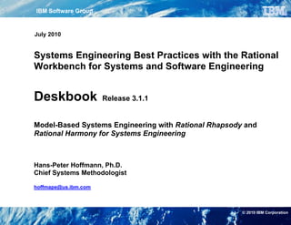
  • 10. Fundamentals of Harmony for Systems Engineering 2 Fundamentals of Harmony for Systems Engineering 2.1 Rational Integrated Systems / Embedded Software Development Process Harmony Fig.2-1 shows the Rational Integrated Systems / Embedded Software The Harmony process consists of two closely coupled sub-processes Development Process Harmony by means of the classic “V” diagram. - Harmony for Systems Engineering and The left leg of the “V” describes the top-down design flow, while the - Harmony for Embedded Real Time Development right hand side shows the bottom-up integration phases from unit test to the final system acceptance. Using the notation of statecharts, the The systems engineering workflow is iterative with incremental cycles impact of a change request on the workflow is visualized by the “high- through the phases requirements analysis, system functional analysis level interrupt”. Whenever a change request occurs, the process will and design synthesis. The increments are use case based. restart at the requirements analysis phase. Change Request Stakeholder Harmony™ for Requirements Systems Engineering System Validation Scenarios (ConOps) Requirements Models, Requirements Plan System Model / Requirements Repository System Use Cases Model Analysis Acceptance Test Executable Scenarios System Functional Use Case Model(s) Analysis System Verification Architectural Analysis Model(s), Plan (Sub-)System System Architecture Model Design Synthesis Integration & Test Component Verification Harmony™ for System Procedure Architecture Embedded RT Baseline SW Module Development Analysis & Design Integration & Test Software Implementation Model SW Implementation & Unit Test Fig.2-1 Rational Integrated Systems / Embedded Software Development Process Harmony 2 | Systems Engineering Best Practices Deskbook © Copyright IBM Corporation 2006, 2010. All Rights Reserved.
  • 11. Fundamentals of Harmony for Systems Engineering The software engineering workflow is characterized by the iterative The system architecture model captures the allocation of the system incremental cycles through the software analysis and design phase, operations to the system architecture that was elaborated in the the implementation phase, and the different levels of integration and previous architectural analysis phase. The correctness and testing. completeness of the system architecture model is verified through Regarding the systems engineering and implementation iterations, it model execution. Once the model is verified, the architectural design should be noted, that the analysis iterations continue through may be analyzed with regard to performance and safety requirements. implementation and testing, thus providing something demonstrable The analysis may include Failure Modes Effects Analysis (FMEA), and with each iteration. Mission Criticality Analysis. It is important to note the creation and reuse of requirements related The baselined system architecture model defines the hand-off to the test scenarios all along the top-down design path. These scenarios subsequent HW/SW development. are also used to assist the bottom-up integration and test phases and, in the case of system changes, regression test cycles. Model-driven software development is supported by the Software Implementation Model. This model is the basis for - either manual or The Harmony process supports Model-Driven Development (MDD). In automatic - code generation [5,6]. a model-driven development, the model is the central work product of the development processes, encompassing both analysis and design. An essential element of the model-driven development process is the Each development phase is supported by a specific type of model. Model/Requirements Repository. It contains the configuration controlled knowledge of the system under development, i.e. Models that support the requirements analysis phase are - Requirements documentation - the Requirement Models and - Requirements traceability - the System Use Cases Model. - Design documentation and - Test definitions A requirement model visualizes the taxonomy of requirements. The system use cases model groups requirements into system use cases. Neither of these models is executable. In the system functional analysis phase the focus is on the translation of the functional requirements into a coherent description of system functions (operations). Each use case is translated into an executable model and the underlying system requirements verified through model execution. There are two types of executable models supporting the design synthesis phase: - Architectural Analysis Model(s) and - System Architecture Model The objective of the architectural analysis model(s) - also referred to as Trade Study Model(s) - is to elaborate an architectural concept for the implementation of the identified operations e.g. through a parametric analysis. © Copyright IBM Corporation 2006, 2010. All Rights Reserved. Systems Engineering Best Practices Deskbook | 3
  • 12. Fundamentals of Harmony for Systems Engineering 2.2 Model-based Systems Engineering Process Key objectives of Harmony for Systems Engineering are: Fig.2-2 depicts an overview of Harmony for Systems Engineering. For each of the systems engineering phases, it shows the essential input • Identification and derivation of required system functions and outputs. • Identification of associated system modes and states • Allocation of the identified system functions and modes/states to a The following paragraphs detail the workflow and artifacts of the subsystem structure model-based systems engineering process and outline an associated With regard to modeling, these objectives imply a top-down approach Requirements Management and Traceability (RT) concept. For a on a high level of abstraction. The main emphasis is on the more application oriented workflow description, please refer to the identification and allocation of a needed functionality and state-based case study in Section 4. behavior, rather than on the details of its functional behavior. Next Iteration or Change Request Stakeholder Requirements Stakeholder Requirements System Requirements Requirements Analysis System Use Cases Model SRS Model / Requirements Repository (Draft) System Use Cases Updated System Requirements System Functional Analysis System-Level Executable Use Case Model(s) (Use Case-Based) ICD Use Case Scenarios (Black-Box) SRS System Operations (Baseline) Non-Functional System Requirements Design Synthesis Updated System Requirements Architectural Analysis Architectural Analysis Model(s) (Trade Study) Architectural Concept UC Activity Diagram(s) (Black-Box) Architectural Design UC Activity Diagram(s) (White-Box) Allocated System Operations UC Activity Diagram(s) (White-Box) Detailed Scenarios (White-Box) Architectural Design System Architecture Model (Baseline) Links providing traceability Logical ICDs to original requirements HW/SW Req Specs HW/SW incl. Test Scenarios Development Fig.2-2 Model-based Systems Engineering 4 | Systems Engineering Best Practices Deskbook © Copyright IBM Corporation 2006, 2010. All Rights Reserved.
  • 13. Fundamentals of Harmony for Systems Engineering 2.2.1 Requirements Analysis into required system functions (“shall” statements) and documented in the Draft System Requirements Specification. For traceability, the The objective of the requirements analysis phase is to analyze the alysis identified system requirements are linked to the associated process inputs. Stakeholder requirements are translated into system stakeholder requirements. requirements that define what the system must do (functional requirements) and how well it must perform (quality of service The next major step in the requirements analysis phase is the requirements) definition of system use cases. A use case describes a specific operational aspect of the system (operational thread). It specifies the The essential steps of the requirements analysis workflow are shown behavior as perceived by the actors (user) and the message flow in Fig.2-3. It starts with the analysis and optional refinement of the between the actors and the use case. An actor may be a person, stakeholder requirements. Output of this phase is the Stakeholder another system or a piece of hardware external to the system under s Requirements Specification. Essentially, stakeholder requirements development (SuD). A use case does not reveal or imply the system’s focus on required capabilities. In the next step, these are transformed internal structure (black box view). Use cases may be structured hierarchically – but care should be taken not to functionally decompose the use cases. Use cases are not [System Use Cases defined] functions, they use functions. There is no “golden rule” with regard to the number of use cases needed to describe a system. Experience [else] shows that for large systems, typically 6 to 24 use cases may be Analyze/Refine Stakeholder Reqs defined at the top level. At the lowest level a use case should be described by at least 5, with a maximum of 25 essential use case Stakeholder Requirements scenarios. At this stage, emphasis is put on the identification of Specification “sunny day” use cases, assuming an error/fail free system behavior. Exception scenarios will be identified at a later stage (=> system Generate Link functional analysis) through model execution. If more than 5 error/fail Stakeholder Reqs System Reqs to System Reqs scenarios are found for a use case, they should be grouped in a separate exception use case, which are then linked to the “sunny day” System use case via an include or extend dependency. Requirements Specification (Draft) In order to assure that all functional and associated performance Define requirements are covered by the use cases, respective traceability System Use Case links need to be established. Link Functional / Performance Once the system-level use cases are defined and the complete Reqs to System Use Case coverage of the functional and associated performance requirements is assured, they need to be ranked according to their importance for [Next System Use Case] the definition of the system architecture. The order defines the [else] increments of the iterative SE workflow. At the end of each iteration Prioritize and Partition System Use Cases this ranking might need to be updated. Fig.2-3 Workflow in the Requirements Analysis Phase © Copyright IBM Corporation 2006, 2010. All Rights Reserved. Systems Engineering Best Practices Deskbook | 5
  • 14. Fundamentals of Harmony for Systems Engineering 2.2.2 System Functional Analysis The main emphasis of the system functional analysis phase is on the Fig.2-4 details the modeling tasks and the associated work products. transformation of the functional system requirements into a coherent First, the use case model context is defined in an Internal Block description of system functions (operations). The analysis is use Diagram. Elements of this diagram are instances of SysML blocks, case-based, i.e. each system-level use case that was identified in the representing the use case and its associated actor(s). At this stage, previous requirements analysis phase is translated into an executable the blocks are empty and not linked. model. The model and the underlying requirements then are verified through model execution. Build Executable Model of Use Case Define Use Case Model Context (UC Internal Block Diagram) [Alternative 3] [Alternative 1] [Alternative 2] Define UC Scenarios Define UC Functional Flow Define UC State-Based Behavior (UC Black-Box Sequence Diagrams) (UC Black-Box Activity Diagram) (UC Statechart Diagram) Derive UC Functional Flow Derive UC Scenarios Derive UC Scenarios from UC Scenarios from UC Functional Flow from UC Statechart Diagram (UC Black-Box Activity Diagram) (UC Black-Box Sequence Diagrams) (UC Black-Box Sequence Diagrams) Define Ports And Interfaces Define Ports And Interfaces (UC Internal Block Diagram) (UC Internal Block Diagram) Document New / Derived Reqs Derive UC State-Based Behavior from UC Black-Box AD and SDs (UC Statechart Diagram) Verify UC Model through Model Execution [else] [Rainy Day Analysis] Extend UC Model w.r.t. Error/Fail Behavior Link UC Block Properties to Reqs Update Draft System Req Spec Fig.2-4 Alternative Approaches of Building an Executable Use Case Model 6 | Systems Engineering Best Practices Deskbook © Copyright IBM Corporation 2006, 2010. All Rights Reserved.
  • 15. Fundamentals of Harmony for Systems Engineering The next step in the modeling workflow is the definition of the behavior activity diagram (ref. Fig.2-5). Ports and interfaces of the use case of the use case block. It is captured by means of three SysML block are created from the sequence diagrams. Lastly, its state-based diagrams: behavior is captured in a statechart diagram. - Activity Diagram, Alternative 3 starts with the definition of the use case state-based - Sequence Diagrams, and behavior. This approach is recommended if the system under design - Statechart Diagram. (SuD) is strongly state-based. In this case, the creation of a use case black-box activity diagram may even be skipped. Use case scenarios Each diagram plays a specific role in the elaboration of the use case then are derived as paths through the statechart diagram. From the behavior. The activity diagram – referred to as Use Case Black-Box sequence diagram then ports and associated interfaces are Activity Diagram - describes the overall functional flow (storyboard) of generated. the use case. It groups functional requirements in actions – in Harmony for Systems Engineering the equivalent of operations - and It should be noted, that regardless of which approach is chosen, the shows, how these actions/operations are linked to each other. The most important diagram in the system functional analysis process is sequence diagram – referred to as Use Case Black-Box Sequence the use case block statechart diagram. It comprises the information of Diagram - describes a specific path through the use case and defines both the black-box sequence diagrams and the use case black-box the interactions (messages) between the operations and the actors. activity diagram and can be verified through model execution. The The statechart diagram aggregates the information from the activity use case black-box activity diagram and the associated black-box diagram (functional flow) and the sequence diagrams (actor sequence diagrams will be reused further down in the design process. interactions). It puts this information into the context of system states Whenever during the use case based system functional analysis new and adds to it the system behavior due to external stimuli of different requirements are identified or high-level requirements are detailed by priority. derived requirements, they need to be documented. Last at the end of There is no mandate directing in which order these diagrams should the system functional analysis phase, these additional requirements be generated. The order may depend on the available information and need to be approved by the stakeholders and exported to the the modeler’s preference. Fig.2-4 shows three alternative requirements traceability tool. approaches: The use case model is analyzed through model execution using the black-box use case scenarios as the basis for respective stimuli. It Alternative 1 starts with the definition of use case scenarios. should be noted, that - following the previously outlined key objectives Customers often describe sequences of required system usage (e.g. of this process - the primary focus is on the verification of the Concept of Operations). Once a set of essential scenarios is generated sequences rather than on the validation of the underlying captured, the identified functional flow is merged into a common functionality. description in an activity diagram. Ports and interfaces are created from the sequence diagrams (ref. section 2.4 Service Request-Driven Modeling Approach). They define the links between the actor(s) and the use case block in the use case model internal block diagram. The final step in this approach is the definition of the state-based behavior of the use case block in a statechart diagram. Alternative 2 starts with the definition of the use case functional flow. This is a common approach, if systems engineers have to elaborate requirements. Typically, customers like to express their requirements from the “big picture” point of view. Once the overall functional flow is defined, use case scenarios are derived from the © Copyright IBM Corporation 2006, 2010. All Rights Reserved. Systems Engineering Best Practices Deskbook | 7