SlideShare uma empresa Scribd logo
1 de 31
Baixar para ler offline
Phone: 978-777-0070 Fax: 978-774-2409140
TECHNICAL
Technical
Index
Wattage Calculation Formulas and Examples . . . . . . . . . . . . . . . . . . . . . . . . .141-144
Properties of Metals . . . . . . . . . . . . . . . . . . . . . . . . . . . . . . . . . . . . . . . . . . . . . . . .145
Properties of Non-Metallic Solids . . . . . . . . . . . . . . . . . . . . . . . . . . . . . . . . . . . . . .146
Properties of Liquids and Gases . . . . . . . . . . . . . . . . . . . . . . . . . . . . . . . . . . . . . . .147
Suggested Watt Densities . . . . . . . . . . . . . . . . . . . . . . . . . . . . . . . . . . . . . . . . . . .148
Estimates of Wattage Required . . . . . . . . . . . . . . . . . . . . . . . . . . . . . . . . . . . . . . .149
Guide for Heat Losses . . . . . . . . . . . . . . . . . . . . . . . . . . . . . . . . . . . . . . . . . . .150-151
Suggested Sheath Materials . . . . . . . . . . . . . . . . . . . . . . . . . . . . . . . . . . . . . .152-155
Thermal Systems . . . . . . . . . . . . . . . . . . . . . . . . . . . . . . . . . . . . . . . . . . . . . . . . . . .156
Installation . . . . . . . . . . . . . . . . . . . . . . . . . . . . . . . . . . . . . . . . . . . . . . . . . . . .157-159
Ohms Law . . . . . . . . . . . . . . . . . . . . . . . . . . . . . . . . . . . . . . . . . . . . . . . . . . . . . . .160
Wiring Diagrams . . . . . . . . . . . . . . . . . . . . . . . . . . . . . . . . . . . . . . . . . . . . . . .160-161
Mathematical Conversions: 162-164
Inches to Millimeters 162
Circumferences and Areas of Circles 163
Areas of Volume, Squares, Geometrical forms
and Conversion Factors 164
Temperature Conversions . . . . . . . . . . . . . . . . . . . . . . . . . . . . . . . . . . . . . . . . . . . .165
Empirical Guideline for Cartridge Heater life . . . . . . . . . . . . . . . . . . . . . . . . . . . . .166
Wire, Cable and Current Capacities . . . . . . . . . . . . . . . . . . . . . . . . . . . . . . . . . . . .167
Wire Gage data . . . . . . . . . . . . . . . . . . . . . . . . . . . . . . . . . . . . . . . . . . . . . . . . . . . .168
Pipe Sizes and Threads . . . . . . . . . . . . . . . . . . . . . . . . . . . . . . . . . . . . . . . . . . . . . .169
Resistance wire - Current VS. Temperature . . . . . . . . . . . . . . . . . . . . . . . . . . . . . .170
Web: www.hotwatt.com Email: sales@hotwatt.com 141
Wattage Calculation Data
Basic Heating Formulas
The following formulae can be employed in determining wattage capacity required for different materials.
Formula A: Wattage required for heat-up =
For specific heat and weights of each material being heated, see tables 1, 2, and 3 on pages 145, 146, and 147
Formula B: Wattage losses at operating temperature = Wattage loss/sq. ft. x Area in sq. ft.
See curves on pages 150-151.
Formula C: Wattage for melting or vaporizing =
When the specific heat of a material changes at some temperature during the heat-up, due to melting (fusion) or evaporation (vapor-
ization), perform Formula A for heat absorbed from the initial temperature up to the temperature at the point of change, add Formula
B, then repeat Formula A for heat absorbed from the point of change to the final operating temperature. See tables 1, 2, and 3 on
pages 145-147, for heats of fusion and vaporization and temperatures at which these changes in state occur.
Specific Applications
For specific applications, substitute the Basic Heat Formulas (A, B, or C above) into the following:
To Heat Liquids
Wattage for initial heat-up = (a) +
Wattage for operating requirements = (a) for new material added + (b)
To insure adequate capacity, add 20% to final wattage figures. This will compensate for added losses not readily computed.
To Melt Soft Metals
Wattage for initial heat-up = (a) to melting point + (c) to melt + (a) to heat above melting point +
Wattage for operating requirements = [(a) to melting point + (c) to melt + (a) to heat above melting point] for added material + 11. To
insure adequate capacity, add 20% to final wattage figures. This will compensate for added heat losses not really computed.
To Heat Ovens
Wattage = (a) (for air) + (a) (all material introduced into oven) + (b)
Add 25% to cover door heat losses
Forced Air Heating
Wattage =
For explanation of Basic Heat Formulas, see examples on pages 142-144.
Weight of material (lbs) x Specific Heat x Temperature Rise ˚F
3.412 x Time (Hours of fraction Thereof)
Weight of material (lbs) x Heat of fusion or vaporization (BTU/lb)
3.412 x Heat up time (Hours of fraction Thereof)
(b)
2
(b)
2
C.F.M. x temperature rise (˚F)
3
TECHNICAL
Technical
Wattage Calculation Formulas
Phone: 978-777-0070 Fax: 978-774-2409142
TECHNICAL
Technical
Wattage Calculation Formulas
Problem 1: Basic Heating and Heat Loss.
A steel mold is being used to form polyethelyne parts. Each hour, 90 ounces of nylon is introduced to the mold. The mold itself measures
10” x 8” x 4”. The mold is attached between two stainless steel platens, each measuring 15” x 12” 11
⁄2” thick. The platens are insulated from the
press mechanism with 1
⁄2” thick insulation. Operating temperature of the mold is 400˚F and is required to reach this temperature in 1 hour with an
ambient temperature of 70˚F.
1) From Table 1, page 145: Specific heat of steel - .12/BTU/lb ˚F
2) From Table 1, page 145: Specific heat of stainless steel - .12/BTU/lb ˚F
3) From Table 2, page 146: Specific heat of polyethelyne - .55/BTU/lb ˚F
4) From Graph 1, page 150: Heat losses curves – A + B @ 400˚F
5) From Table 1, page 145: Converting cubic inches into pounds (density lb/cu. in.)
Formula A: Wattage required for heat-up
To heat mold = 2,110 watts
To heat Platens = 1,800 watts
To heat Polyethelyne = = 300 watts
Compensation Factor 20% (2,110 + 1,800 + 300) = 840 watts
Total wattage required for Heat-up = 5,050 watts
(10” x 8” x 4”) = 320 cu.in. x 2 x .284 = 181.7 (lbs) x .12 BTU/lb ˚F x (400 - 70)˚F
3.412 x 1
(15” x 12” x 11
⁄2”) = 270 cu.in. x 2 x .286 = 154.5 (lbs) x .12 BTU/lb ˚F x (400-70) ˚F
3.412 x 1
5.6 (lbs) x .55BTU/lb ˚F x (400-70) ˚F
3.412 x 1
90
16
Lower Platen
Web: www.hotwatt.com Email: sales@hotwatt.com 143
Formula B: Wattage losses at operating temperature (see graphs on pages 150 and 151).
Heat loss from mold (vertical surfaces)
= 2 sq. ft. x 350w/sq.ft./hr. = 700 watts
Heat loss from platen (vertical surfaces)
= 1.1 sq. ft. x 350w/sq.ft./hr. = 385 watts
Heat loss from platen (horizontal surfaces, uninsulated)
= 1.3 sq. ft. x 250w/sq.ft./hr. = 350 watts
Heat loss from platen (insulated surface) 250 watts
= 2.5 sq. ft. x 100w/sq.ft./hr. =
Compensation factor: 20% (700w + 385w + 350w + 250w) = 340 watts
Total wattage losses at operating temperature = 2,025 watts
Total wattage required for heat-up = 5,050 watts
Total wattage required = 7,075 watts
The number of holes in the mold would dictate the number of heaters required. Divided the wattages by the number of heaters will equal
the wattage rating of each heater.
Problem 2: Paraffin melting
An open top uninsulated steel tank: 18” wide, 24” long and 18” deep weighs 140 pounds. This tank contains 168 pounds of paraffin which
needs to be heated from 72˚F to 150˚F in 2 1
⁄2” hours.
1.) From Table 1, page 145: Specific heat of steel - .12 BTU/lb-˚F
2.) From Table 2, page 146: Specific heat of solid paraffin - .70 BTU/lb-˚F
3.) From Table 2, page 146: Melting point of paraffin: -133˚F
4.) From Table 3, page 147: Heat of fusion of paraffin - 63 BTU/lb
5.) From Table 3, page 147: Specific heat of melted paraffin - .71 BTU/lb-˚F
6.) From Graph 5, page 151: Surface loss at 150˚F:70w/sq.ft./hr.
7.) From Graph 1, page 150: Surface loss at 150˚F:55w/sq.ft./hr.
Formula A: Wattage required for heat-up
To heat tank
= 155 watts
To heat paraffin
= 845 watts
To heat melted paraffin (fusion occurs at melting point)
= 240 watts
Formula C: Wattage for melting or vaporizing
Heat of fusion to melt paraffin
= 1,245 watts
10” x 4” x 4” + 8” x 4” x 4”
144”
11
⁄2” x 15” x 4” + 11
⁄2” x 12” x 4”
144”
15” x 12” x 2” - (10” x 8” x 2”)
144”
15” x 12” x 2”
144”
140lb x .12 BTU/lb-˚F x (150 - 72)
3.412 x 2.5
168lb x .70 BTU/lb-˚F x (133 - 72) ˚F
3.412 x 2.5
168lb x .71 BTU/lb-˚F x (150 - 133) ˚F
3.412 x 2.5
168lb x 63 BTU/lb
3.412 x 2.5
Technical
Wattage Calculation Formulas
TECHNICAL
Phone: 978-777-0070 Fax: 978-774-2409144
TECHNICAL
Technical
Wattage Calculation Formulas
Formula B: Wattage losses at operating temperature (see graphs on pages 150 and 151)
Average paraffin surface loss
3sq.ft. x 70w/hr. = 210 watts
Total losses
13.5sq.ft. x 55w/hr. = 740 watts
Compensation factor
20% (155 + 845 + 239 + 1,245 + 210 + 740) = 685 watts
Total wattage required = 4,120 watts
In addition to calculating the watts required for initial heat-up and heat losses, operating heat requirements must be calculated. Steel pins,
each weighing .175 pounds, are to be placed in a 70 pound steel rack and dip-coated in the melted paraffin. 1,750 pins can be processed
per hour with 25 pounds of paraffin.
Formula A: Wattage required for heat-up
To heat pins and rack
= 1,030 watts
To heat additional solid paraffin
= 310 watts
To heat additional melted paraffin (fusion occurs at melting point)
= 90 watts
Formula C: Wattage for melting or vaporizing
Heat of fusion, to melt additional paraffin
= 460 watts
Formula B: Wattage losses at operating temperature (see graphs on pages 150 and 151).
Paraffin surface loss
3sq.ft. x 70w/sq.ft./hr. = 210 watts
Tank surface loss
13.5sq.ft./ x 55w/sq.ft./hr = 740 watts
Compensation factor
20% (1,058 + 310 + 90 + 460 + 210 + 740) = 575 watts
Total wattage required = 3,415 watts
In the above calculations, the heat-up requirement is the greatest, therefore a heater with a wattage rating of 4,120 watts should be used
in this application. The recommended watt density on the heater for this application is 16 watts per square inch (see page 148, table 1).
(1750 x .175 + 70)lbs/hr x .12BTU/lb/˚F x (150 - 72) ˚F
3.412 x 1 hour
25lbs/hr x .70BTU/lb˚F x (133 - 72) ˚F
3.412 x 1 hour
25lbs/hr x .71BTU/lb˚F x (150-133)˚F
3.412 x 1 hour
25lbs/hr x 63BTU/lb
3.412 x 1 hour
Web: www.hotwatt.com Email: sales@hotwatt.com 145
Density Average Thermal Conductivity Latent Heat
(at or near room temp.) Specific Heat (at or near room temp.) of Fusion
Material (lb/cu.in.) (BTU/lb/˚F) K(BTU/hr./sq.ft./˚F) Melting Point (˚F) (BTU/lb)
Aluminum 2024-IT3 .100 .24 840 935 167
Aluminum 1100-00 .098 .24 1540 1190 169
Aluminum 30003 .099 .24 — 1190 167
Antimony .245 .052 — 1166 25
Brass, Yellow .306 .096 830 1710 —
Brass, Red .316 .100 — 1877 —
Bronze .318 .104 — 1832 75
Copper .322 .095 2680 1981 91.1
Gold .697 .030 — 1945 29
Incoloy 800 .290 .13 80 2475 —
Inconel 600 .304 .126 103 2500 —
Iron, Cast .260 .12 346 2150 —
Iron, Wrought .278 .12 — 2800 —
Lead, Solid .410 .032 240 620 11.3
Lead, Liquid .387 .037 108 — —
Magnesium .063 .27 1106 1202 160
Monel 400 .319 .11 151 2370 133
Monel 200 .321 .12 436 2615 133
Nickel 200 .321 .12 436 2615 133
Nickel Silver 18%80%NI20%CN .314 .095 — 1931 —
Nichrome .303 .11 — 2550 —
Platinum .775 .032 — 3224 49
Silver .379 .057 2900 1760 38
Solder 50%Pb 50%SN .323 .051 310 361 17
Steel .284 .122 460 2760 —
Stainless Steel 304 .286 .12 105 2550 —
Stainless Steel 316 .288 .118 108 2650 —
Stainless Steel 430 .275 .11 — 2650 —
Tin, Solid .263 .065 455 450 26.1
Tin, Liquid .253 .052 218 — —
Titanium 99% .164 .13 112 3035 —
Type Metal 85%Pb 15%Sb .387 .040 — 500 14±
Table 1: Properties of Metals
Technical
Properties of Metals
TECHNICAL
Phone: 978-777-0070 Fax: 978-774-2409146
TECHNICAL
Technical
Properties of Non-Metallic Solids
Density Average Thermal Conductivity
(at or near room temp.) Specific Heat (at or near room temp.)
Material (lb/cu.in.) (BTU/lb/˚F) K(BTU/hr./sq.ft./˚F) Melting Point (˚F)
Asbestos .070 .25± 5.2 —
Asphalt .076 .40 5.3 —
Brickwork & Masonry .076 .22 3.7 —
Beeswax .035 — — 144
Carbon .080 .28 165 6700
Cellulose Acetate .047 .3 to .5 1.2 to 2.3 —
Butyrate .043 .3 to .4 1.2 to 2.3 —
Delrin .051 .35 1.6 —
Glass .101 .161 7.5 —
Graphite .075 .20 — —
Lava, Grade A .085 — 9± 2912
Mica .102 .21 3.0 —
Magnesium, Compacted .112 .209 20 —
Nylon .040 .4 1.5 —
Paper .034 .45 .62 —
Paraffin .032 .70 1.6 133
Phenolic (general) .046 .40 .6 to 1.2 —
Porcelain .114 .26 — 3326
Polyethylene .035 .55 2.3 —
Polystyrene .038 .32 .7 to 1.0 —
Quartz .080 .21 — 3150
Rubber .044 .44 1.1 —
Rosin .380 .5 — —
Sugar .073 .30 — —
Steatite .094 .20 17.5 to 23 2500±
Sulfur .075 .175 1.9 246
Teflon .078 .25 1.7 —
Vinyl .046 .3 to .5 .8 to 2.0 —
Wood, Oak .029 .57 1.1 —
Table 2: Properties of Non-Metallic Solids
Web: www.hotwatt.com Email: sales@hotwatt.com 147
Density Average
(at or near room temp.) Specific Heat Heat of Vaperation
Liquids (lb/cu.ft.) (BTU/lb/˚F) Boiling Point (˚F) (BTU/lb)
Acetic Acid 20% 64.1 .91 214 ± 810 ±
Alcohol (Ethyl) 49.6 .60 173 367
Benzene 56 .45 175 166
Brine (25% NaCL) 74 .81 221 ± 728 ±
Caustic Soda (18% NaOH) 74.9 .84 221 ± 795 ±
Dowtherm A 66.1 .44 496 42.2
Ether 46 .503 95 160
Ethylene Glycol 70.5 .602 387 —
Fish Oil 70.5 .602 387 —
Fuel Oil, Bunker C 61 .50 — 145-150
Freon 12 82.7@70psig .23 -21.6 62
Gasoline 48.6 .675 158-194 137
Glue (1
⁄3 dry glue, 2
⁄3 water) 69 .895 — —
Glycerine 79 .58 554 —
Kerosene 51.5 .47 — 108
Mercury 845 .0333 675 117
Milk 64.5 1(approx.) — —
Molasses 87.4 .6 — —
NaK (78%K) 46.2 .21 1446 —
Nitric Acid 7% 64.7 .92 220 ± 918 ±
Oil, Cottonseed 60 .47 — —
Oil, Machine 58 .40 — —
Oil, Olive 58 .471 570 ± —
Paraffin (melted) 47.1 .71 1400 63
Petroleum 56 .51 — —
Potassium (K) 44.6 .18 — —
Sodium (Na) 51.2 .3 1621 1810
Sulfur (melted) — .234 601 652
Thermonal FR-2 90.6 .3 648 ± —
Turpentine 54.3 .41 318 123
Vegetable Oil 57.5 .43 ± — —
Water 62.3 1.0 212 970
Table 3: Properties of Liquids
Density (at or near room temp.
and atmospheric pressures) Specific Heat
Gasses (lbs/cu.ft.) (BTU/LB/˚F)
Air @ 80˚F .073 .240
Air @ 400˚F .046 .245
Ammonia .044 .523
Acetylene .073 .35
Argon .102 .125
Carbon Dioxide .113 .199
Carbon Monoxide .072 .248
Chlorine .184 .115
Hydrochloric Acid .094 .194
Hydrogen .0052 3.39
Methane .041 .528
Nitrogen .072 .248
Oxygen .082 .218
Sulphur Dioxide .172 .152
Water Vapor @ 212˚F .037 .482
Table 4: Properties of Gases
Technical
Properties of Liquids and Gases
TECHNICAL
Phone: 978-777-0070 Fax: 978-774-2409148
TECHNICAL
Technical
Suggested Watt Densities
The rates below are recommended watt densities for use with
various materials. Safe values vary with operating temperature,
flow velocity, and heat transfer rates. In general, the higher the
material temperature, the lower the watt density should be,
especially those materials which coke or carbonize, such as oils.
Watt densities should be low if a material is being heated to a
temperature near where the change of state to a vapor occurs
(water to steam @212˚F.) since the vapor state has much poorer
heat transfer capabilities.
Maximum Maximum
Operating Watts Per
Material being heated Temp. ˚F Sq. In.*
Acid Solutions:
Acetic 212 40
Chromic (5%) Boiling 40
Citric Boiling 40
Ferric Boiling 40
Chloride (40%)
Hydrochloric 150 30
Nitric (50%) Boiling 40
Sulphuric Boiling 30
Alkai & selected oakite
cleaning solution 212 40
Asphalt binder, tar, other
viscous compounds 200 8
300 7
400 6
500 5
Caustic Soda 2% 210 45
10% 210 25
75% 180 25
Coffee (direct immersion) Boiling 90
Dowtherm A®
Flowing at 1ft/sec or more 750 22
Non-flowing 750 10
Ethylene Glycol 300 30
± Fuel Oils
Grades 1 & 2 (Distillate) 200 22
Grades 4 & 5 (Residual) 200 13
Grades 6 & Bunker C (Residual) 160 8
Gasoline, Kerosene 300 20
Glue (heat indirectly using water bath) 100
Liquid ammonia plating baths 50 25
** Lubrication Oils
SAE 10, @ 130˚F 250 22
SAE 20, @ 130˚F 250 22
SAE 30, @ 130˚F 250 22
SAE 40, @ 210˚F 250 13
SAE 50, @ 210˚F 250 13
**Some oils contain additives that will boil or carbonize at low
watt densities. Where oils of this type are encountered a watt
density test should be made to determine a satisfactory watt
density.
Maximum Maximum
Operating Watts Per
Material being heated Temp. ˚F Sq. In.*
Metal melting pot 500 to 900 20-27
Mineral oil 200 20
400 16
Molasses 100 2-3
Molten salt bath 800-950 40
Molten tin 600 20
Oil draw bath 600 20
400 24
Paraffin or wax 150 16
Photographic solutions 150 70
Plating solutions:
Cadmium plating 40
Chrome plating 40
Copper plating 40
Nickel plating 40
Tin plating 40
Zinc plating 40
Salt Bath 900 30
Sea Water Boiling 90
Sodium cyanide 140 40
Steel tubing cast into aluminum 500 to 750 50
Steel tubing cast into iron 750 to 1000 55
Heat transfer oils 500 22
flowing at 1 ft/sec or more 600 22
650 22
750 15
Tricholretylene 150 20
Vapor degreasing solutions 275 20
Vegetable oil (fry kettle) 400 30
Water (process) 212 60
Water (washroom) 140 80-90
* Maximum watt densities are based on heated length, and may
vary depending upon concentration of some solutions. Watt
density should be kept as low as possible in corrosive applica-
tions since higher watt densities accelerate corrosive attack on
element sheaths. Consult factory for limitations.
Technical
Estimates of Wattage Required
Web: www.hotwatt.com Email: sales@hotwatt.com 149
TECHNICAL
Lbs. of
Steel
25
50
100
150
200
250
300
400
500
600
700
800
900
1000
Temperature Rise F˚
50˚ 100˚ 200˚ 300˚ 400˚ 500˚ 600˚
Kilowatts to heat in one hour
.06 .12 .25 .37 .50 .65 .75
.12 .25 .50 .75 1.00 1.25 1.50
.25 .50 1.00 1.50 2.00 2.50 3.00
.37 .75 1.50 2.25 3.00 3.75 4.50
.50 1.00 2.00 3.00 4.00 5.00 6.00
.65 1.25 2.50 3.75 5.00 6.25 7.50
.75 1.50 3.00 4.50 6.00 7.50 9.00
1.00 2.00 4.00 6.00 8.00 10.00 12.00
1.25 2.50 5.00 7.50 10.00 12.50 15.00
1.50 3.00 6.00 9.00 12.00 15.00 18.00
1.75 3.50 7.00 10.50 14.00 17.50 21.00
2.00 4.00 8.00 12.00 16.00 20.00 24.00
2.25 4.50 9.00 13.50 18.00 22.50 27.00
2.50 5.00 10.00 15.00 20.00 25.00 30.00
Kilowatt Hours to Heat Steel
A 20% Safety Factor is included to compensate for high heat loss-
es and/or low voltage.
.66 5
1.3 10
2.0 13
2.7 20
3.3 25
4.0 30
5.3 40
6.7 50
8.0 60
9.4 70
10.7 80
12.0 90
13.4 100
16.7 125
20.0 150
23.4 175
26.7 200
33.7 250
40 300
53.4 400
66.8 500
Temperature Rise F˚
20˚ 40˚ 60˚ 80˚ 100˚ 120˚ 140˚
Kilowatts to heat in one hour
0.3 0.5 0.8 1.1 1.3 1.6 1.9
0.5 1.1 1.6 2.1 2.7 3.2 3.7
0.8 1.6 2.4 3.2 4 4.8 5.6
1.1 2.2 3.2 4.3 5.3 6.4 7.5
1.3 2.7 4 5.3 6.7 8 9.3
1.6 3.2 4.8 6.4 8 9.6 12
2.1 4 6.4 8.5 11 13 15
2.7 5.4 8 10.7 13 16 19
3.3 6.4 9.6 12.8 16 19 22
3.7 7.5 11.2 15 19 22 26
4.3 8.5 13 17 21 26 30
5 10 14.5 19 24 29 34
5.5 11 16 21 27 32 37
7 13 20 27 33 40 47
8 16 24 32 40 48 56
9 18 28 37 47 56 65
11 21 32 43 53 64 75
13 27 40 53 67 80 93
16 32 47 64 80 96 112
21 43 64 85 107 128 149
27 53 80 107 133 160 187
Kilowatt Hours to Heat Water
Amount of Liquid
Cubic
Ft.
Gallons
.5 3.74
1 7.48
2 14.96
3 22.25
4 29.9
5 37.4
10 74.8
15 112.5
20 149.6
25 187
30 222.5
35 252
40 299
45 336.5
50 374
55 412
60 449
65 486
70 524
75 562
Temperature Rise F˚
50 100 200 300 400 500
.3 .5 1 2 2 3
.5 1 2 3 4 6
1 1 2 4 6 11
2 3 6 9 12 16
2 4 8 12 16 22
3 4 9 15 20 25
5 9 18 29 40 52
7 14 28 44 60 77
9 18 37 58 80 102
11 22 46 72 100 127
13 27 56 86 120 151
16 31 65 100 139 176
18 36 74 115 158 201
20 40 84 129 178 226
22 45 93 144 197 252
25 49 102 158 217 276
27 54 112 172 236 302
29 58 121 186 255 326
32 62 130 200 275 350
34 67 140 215 294 375
Kilowatt Hours to Heat Oil
Amount of Oil
Cubic
Ft.
Gallons
Add 5% for uninsulated tanks.
A 20% Safety Factor is included to compensate for high heat losses
and/or low voltage.
Phone: 978-777-0070 Fax: 978-774-2409150
TECHNICAL
Technical
Guide for Heat Losses
2400
2200
2000
1800
1600
1400
1200
1000
800
600
400
200
200 300 400 500 600 700 800 900
WattsPerSquareFoot
Temperature ˚F
Graph 1: Losses from Uninsulated Metal Surfaces.
A-Oxidized Steel
B-Oxidized Steel
C-Oxidized Steel
A-Oxidized Aluminum
B-Oxidized Aluminum
C-Oxidized Aluminum
Semi-Dull Copper
1600
1500
1400
1300
1200
1100
1000
900
800
700
600
500
400
300
200
100
50
80 90 100 110 120 130 140 150 160 170 180 190 200 210
WattsPerSquareFootofWaterSurface
Temperature of Water ˚F
Graph 2: Losses from Open Hot Water Tanks
2 F.P.S. 40% Relative Humidity
1 F.P.S. 40% Relative Humidity
2 F.P.S. 60% Relative Humidity
1 F.P.S. 60% Relative Humidity
Curves “A” show heat losses from
vertical surfaces of tanks, pipes, etc.
and also top surface losses from a
horizontal surface laid flat.
Curves “B” show average heat losses
from top and bottom surfaces of a
horizontal surface laid flat.
Curves “C” show heat losses from
bottom surface of a horizontal sur-
face laid flat.
All curves presuppose still air
(approx. one foot per second) at
70˚F.
Web: www.hotwatt.com Email: sales@hotwatt.com 151
1200
1100
1000
900
800
700
600
500
400
300
200
100
300 400 500 600 700 800 900
WattsPerSquareFoot
Temperature ˚F
Graph 3: Losses from Molten Metal Surfaces.
90
80
70
60
50
40
30
20
10
5
0
100 200 300 400 500 600 700 800 900 1000
WattsPerSquareFoot
Temperature Difference ˚F
Graph 4: Losses through Insulated Walls (ovens, pipes, etx.)
2”Thickness of Insulation
3”Thinkness of Insulation
4”Thickness of Insulation
1000
900
800
700
600
500
400
300
200
100
0 70 100 200 300 400 500 600
WattsPerSquareFoot
Temperature of Oil or Paraffin ˚F
Graph 5: Losses from Surfaces of Oil Baths.
Technical
Guide for Heat Losses
TECHNICAL
Phone: 978-777-0070 Fax: 978-774-2409152
TECHNICAL
Technical
Suggested Sheath Materials
The following table of recommendations should only be used as a guide. The proper choice should be based upon your knowledge of the
conditions which exist in each application.
Iron Cast Iron 300 Series Inconel
Compound Copper Lead Aluminum Nickel and Steel NI Resist Stainless Monel Incoloy
Acetic Acid,
Crude 2 x 2 2 x 3 2 2 3
Pure 2 2 1 2 — x — 1 3
Vapors 2 x 3 2 — x — 2 3
150 PSI; 400˚F 2 x 3 2 — — — 2 3
Acetone — — — — 3 2 1 — —
Alboloy Process — — — — 1 — — — —
Aluminum Sulphate 2 1 3 3 x 3 2 2 —
Ammonia Gas
Cold 3 1 1 — 1 1 1 1 —
Hot x x — — 3 3 3 3 —
Ammonia and Oil — — — — 1 — — — —
Ammonium Chloride x 1 x 2 3 1 2 2 —
Ammonium Hydroxide x 1 2 — 1 1 1 3 1
Ammonium Nitrate x x 2 — 1 3 1 3 —
Ammonium Sulphate 2 1 — — 1 1 1 1 —
Amyl Alcohol 1 — — — — — — 1 —
Anhydrous Ammonia x — — — 1 — — — —
Aniline, Aniline Oil x — x — 1 — 1 1 —
Aniline Dyes — — — — — — 1 1 —
Anodizing Solutions 10% — — — — 3 — 1 — —
Chromic Acid 96˚F — — — — 3 — 1 — —
Sulphuric Acid 70˚F — 1 — — — — — — —
Sodium Hydroxide Alkaline — — — — 1 — — — —
Nigrosine Black Dye — — — 2 — — — 1 —
Nickel Acetate — 3 — 2 — — — 1 —
Barium Hydroxide x x x 1 — — 1 — —
Barium Sulphide x 1 — — — — 1 1 —
Bleaching Solution — — — 2 — — — 1 —
11
⁄2lb. Oxalic Acid per
Gallon of H2O at 212˚F — — — — — — — — —
Bonderizing — — — — 3 2 1 — —
Cadmium Plating — — — — — — — — 1
Carbolic Acid, Phenol x 1 1 — 3 3 1 1 1
Carbon Dioxide
Dry 1 1 1 — 1 1 1 1 1
Wet 2 x 2 — 2 3 1 1 1
Carbon Tetrachloride 3 2 3 — 3 3 3 1 1
Castor Oil — — 1 — 1 — 1 1 1
Chloroacetic Acid x x x 2 x — x — —
Chlorine
Dry 1 1 1 — 1 1 1 1 —
Wet x 2 x — x x x x —
Chromic Acid x 1 x — 3 3 1 2 3
Chrome Plating — 1 — — — — — — —
Citric Acid 1 1 1 — x 3 1 1 1
Cobalt Acetate 130˚F — — — — — — — 1 1
Coconut Oil — — — 1 — — — 2 —
Copper Chloride 3 1 x — 2 — x 2 —
Copper Cyanide — — — — 1 — — — —
Copper Plating — — — — 1 — — — —
Copper Sulphate 3 1 x — x 3 1 1 1
Creosote 1 — 1 — 1 1 1 1 —
Resistance Ratings: 1 = Good 2 = Fair 3 = Depends on Conditions x = Unsuitable
Web: www.hotwatt.com Email: sales@hotwatt.com 153
Iron Cast Iron 300 Series Inconel
Compound Copper Lead Aluminum Nickel and Steel NI Resist Stainless Monel Incoloy
Deoxidine — — — — — — 1 — —
Deoxylyle — — — — — — 1 — —
Dipenyl 300˚ - 350˚F — — — — 1 — — — —
Di Sodium Phosphate
25% 180˚F — — — — 1 — — — —
Diversey No. 99 — — — — 1 — — — —
Downtherm — — — — 1 — — — —
Ethers 1 1 1 — 1 — — 1 1
Ethyl Chloride 1 — — 1 1 — 1 1 —
Ethylene Gycol 300˚F — — — — — — 1 1 —
Ferric Chloride x x x x x x x x x
Ferric Sulphate x 1 x x x x 2-304 x 3
— — — — — — 1-316 — —
Formaldehyde 2 x 2 — 2 2 1 1 1
Formic Acid 2 x x 3 x — 2 3 3
Freon 1 1 1 — 3 1 3 1 —
Fuel Oil 1 1 — — 1 — 1 1 —
Fuel Oil, Acid 3 1 — — 3 — 3 1 —
Gasoline, Sour 3 1 3 — 3 3 1 1 1
Gasoline, Refined 1 1 1 — 1 1 1 1 1
Glycerin, Glycerol 2 1 1 — 1 1 1 1 —
Holdens 310A Tempering Bath — — — 1 — — — — —
Houghtons Mar Tempering Salt — — — 3 3 — — — —
Hydrochloric Acid
< 150˚F x 2 x 3 x x x 3 —
> 150˚F x x x 3 x — x 3 —
Hydrofluoric Acid
Cold < 65% 3 2 x x x x x 2 —
> 65% 2 3 x — 2 — x 1 —
Hot < 65% x x x x x — x 3 —
> 65% 2 x x — 3 — x 1 —
Hydrogen Peroxide x 2 1 2 x x 1 2 1
Irdite 1-part and 5-parts
water 200˚F — 1 — — — — — — —
Isoproponel 2 — — — 3 — — 1 —
Kerosene 1 1 — — 1 — 1 1 1
Kolene — — — 1 — — — — —
Lacquer solvents 3 — 1 — 3 1 1 1 —
Lard — — — — 2 — — — —
Linseed oil 1 1 1 — 1 — 1 1 1
Magnesium chloride 2 x x 2 2 2 2 2 —
Magnesium hydroxide x — x 1 1 1 1 1 —
Magnesium sulphate 1 — 2 — 1 1 1 1 —
Mercuric chloride x — x x 3 3 x x x
Mercury x — x — 1 1 1 1 1
Methyl alcohol, methanol 1 1 1 — 1 — 1 1 —
Methyl chloride 1 1 — 1 1 — — 1 —
Mineral oils 1 1 1 — 1 — 1 1 1
Naphthalene — — — — 1 — — — —
Nickel chloride x — x — — — 2 3 —
Nickel plating, bright — 1 — — — — — — —
Nickel plating, dull — 1 — — — — — — —
Nickel sulphate x — x — — — 1 3 x
Nitric acid,
Crude x x 3 x x — 3 x x
Concentrated x x 1 x x — 2 x x
Diluted x x x x x — 1 x x
Resistance Ratings: 1 = Good 2 = Fair 3 = Depends on Conditions x = Unsuitable
Technical
Suggested Sheath Materials (con’t)
TECHNICAL
Phone: 978-777-0070 Fax: 978-774-2409154
TECHNICAL
Technical
Suggested Sheath Materials (con’t)
Iron Cast Iron 300 Series Inconel
Compound Copper Lead Aluminum Nickel and Steel NI Resist Stainless Monel Incoloy
Nitrbenzene 2 — — — 1 — 1 — —
Oakite No. 20 — — — — 1 — — — —
Oakite No. 23 — — — — 1 — — — —
Oakite No. 24 — — — — 1 — — — —
Oakite No. 30 — — — — 1 — — — —
Oakite No. 32 — — — — — — — — —
Oakite No. 33 — — — — — 1-347 — — —
Oakite No. 36 — — — — — — — — —
Oakite No. 51 — — — — 1 — — — —
Oakite No. 90 @ 180˚F — — — — 1 — — — —
Oleic acid x x 1 1 3 3 1 1 1
Oxalic acid 3 x 1 — 3 3 3 1 —
Paraffin — — — — 1 — — — —
Parkerizing — — — — 3 2 1 — —
Perchlorethylene — — — — — — 1 — —
Permachlor — — — — — — 1 — —
Petroleum oils, crude
<500˚F 3 3 1 3 1 1 1 3 —
>500˚F x x 1 x 1 1 1 x —
<1000˚F x x x x x — 3 x —
— — — — — — 1-347 — —
Phenol 85%, 120˚F — — — 1 3 — 1 — —
Phosphoric acid
Crude x 3 x x 3 — 3 x —
Pure <45% 2 1 3 3 x — 1 2 —
>45% Cold 2 1 x 3 x — 1 2 —
>45% Hot 3 x x — x — x-304 3 —
— — — — — — 3-316 — —
Photo fixing bath — — — — — — 1 3 —
Picric acid water solution x x x x 3 — 1 3 —
Potassium chloride 1 1 3 1 1 1 1 1 —
Potassium cyanide x x x — 1 — 1 1 —
Potassium dichromate 208˚F — — — — — — 1-347 — —
Potassium hydroxide x x x 1 3 1 2 1 —
Potassium sulphate 1 1 1 1 1 1 2 1 —
Prestone 350˚F — — — — 1 — — 1 —
R5 Bright Dip for copper
polish @ 180˚F — — — — — — 1-316 — —
Soap solutions 3 1 — — 1 1 1 1 —
Sodium carbonate <20% — — — — 1 — — — —
Sodium chloride 2 1 x 1 1 1 2-304 1 1
— — — — — — 1-316 — —
Sodium cyanide x x x — 1 3 1-316 2 —
Sodium hydroxide x 2 x 1 1 1 2 1 1
Sodium hypochlorite 3 x x 3 x 3 x 3 —
Sodium nitrate 2 1 1 1 1 1 2-304 1 1
— — — — — — 1-316 — —
Sodium peroxide — — 1 1 3 1 1 1 —
Sodium silicate 3 x x 1 1 1 1-316 1 —
Sodium sulphate 1 1 3 1 1 1 1 1 1
Sodium sulphide x 1 x 2 1 1 1 2 1
Soybean oil — — — — — — 1 — —
Steam
<500˚F 1 3 1 1 1 — 1 1 1
500-1000˚F 3 x 3 3 3 — 1 3 1
>1000˚F x — x x x — 1 x 1
Stearic acid 3 1 3 1 3 3 1 1 1
Resistance Ratings: 1 = Good 2 = Fair 3 = Depends on Conditions x = Unsuitable
Web: www.hotwatt.com Email: sales@hotwatt.com 155
Iron Cast Iron 300 Series Inconel
Compound Copper Lead Aluminum Nickel and Steel NI Resist Stainless Monel Incoloy
Sulphur x — 1 x 1 3 2 x 1
Sulphuric acid<10%
Cold 3 1 3 3 x — 2 3 —
Hot x 1 3 x x — 2-316 3 —
— — — — — — x-304 — —
10-75% Cold x 1 3 3 x — x-304 3 —
— — — — — — 2-316 — —
Hot x 1 x x x — x 3 —
75-95% Cold x 1 3 3 3 — 1 3 —
Hot x 1 x x 2 — x 3 —
Fuming x 1 3 x 3 2 3-304 x —
— — — — — — 2-316 — —
Sulphurous acid 3 1 3 x 1 — 3-316 x —
— — — — — — x-304 — —
Tannic acid 1 x x 1 — — 2 1 —
Tar — — 1 — 1 — 1 — 1
Tartaric acid — 1 1 3 — — 3-304 3 —
— — — — — — 1-316 — —
Tetrachlorethylene — — — — 1 — — — —
Thermoil GranodineTM
— — — — 2 — — — —
TherminolTM
Fr. 1-8-12W/Sq.In.640˚F — — — — 1 — — — —
Tin plating — — — 1 — — — — —
Toluene — 1 1 — 1 — 1 1 —
Triad solvent — — — — 3 — — — —
Trichloroethylene 3 2 3 — 3 3 3 1 —
Turco No. 2623 — — — — 1 — — — —
Turpentine 3 1 1 — 3 1 1 1 —
Urea ammonia liquor 48˚F — — — — 1 — — — —
Vegetable oil — — — — — — 1 — —
Vinegar — — 3 — 3 — 2-304 1 —
— — — — — — 1-316 — —
Water, acid mine
containing oxidizing salts 3 3 3 3 x 3 1 x —
no oxidizing salts — — 1 — 3 1 x 1 —
Water, fresh 1 1 1 — 3 1 1 1 1
Distilled, Lab grade x x 1 1 x x 1 3 1
Return condensate 1 1 1 — 1 1 1 1 1
Water, sea water 3 1 x — 3 1 2 1 2
Whiskey and wines 1 — — — x 3 2-304 1 1
— — — — — — 1-316 — —
X-ray solution — — — — — — 1 — —
Zinc chloride x 1 x — 3 3 x 1 —
Zinc plating — — — — 1 — — — —
Zinc sulphate x — 3 — 3 1 1 1 1
Resistance Ratings: 1 = Good 2 = Fair 3 = Depends on Conditions x = Unsuitable
Because so many Factors are beyond our Power to control we cannot be responsible for any electric immersion heater failure
that can be attributed to corrosion. This is in view of any warranties, written or verbal, relative to heater performance in a
corrosive environment.
Technical
Suggested Sheath Materials (con’t)
TECHNICAL
Phone: 978-777-0070 Fax: 978-774-2409156
TECHNICAL
Technical
Thermal Systems
Thermal Systems
The result obtained with a precision temperature controller, as with
any tool, depend upon how skillfully it is used. Close temperature
control can be maintained only if the thermal system is properly
designed so that it responds quickly and accurately to operating
conditions.
Thermal systems have four elements, all of which contribute to
systems control performance. They are: 1. WORK (or load) — the
material or product which must be maintained at a controlled
temperature; 2. HEAT SOURCE — the device which delivers the heat
used by the system, such as gas, oil, or electric heaters; 3. HEAT
TRANSFER MEDIUM — the material which transmits the heat from
the heat source to the work; 4. CONTROLLER — the instrument
which controls the heat flow on the basis of the difference between
sensed temperature and controller’s set point.
In addition, careful consideration must be given to the physical
make-up of the system. The proper location of heat sensor and
work-load, a good selection of the heat transfer medium, and use of
reliable components are all essential to the development of a good
thermal system.
Although in practice, thermal systems are not purely steady or
variable, they usually are predominantly one or the other.
For basic system design, the following rule of thumb will be helpful:
where the heat demand is relatively steady, the sensing element of
the controller should be placed close to the heat source; where the
demand is largely variable, it should be near the work area. A
complicated system may require several different sensing element
locations before a suitable one is found. One should always
remember, however that the element should be closer to the area
where a temperature change must be sensed with minimum thermal
lag. (Thermal lag is the delay in heat transfer from place to place in
the thermal system).
The effect of various sensing element locations on the control of
predominantly static or dynamic systems is clearly illustrated in
Fig. 1.
Fig 2 applies to liquid and gas systems which require additional
considerations. Because the heat demand is basically steady, the
sensing element should normally be located close to and above the
heat source to minimize system bandwidth. (Bandwidth is the total
temperature variation above and below the average operating
temperature measured at some point in the system).
Fig. 3: Close grouping of heater, sensing element and work. Where
this layout is feasible, it gives excellent control under most conditions
and is desirable when the thermal load changes frequently. The heat
transfer paths from he work and heater to the thermostat are short,
so that thermal lag is slight. System inertia is low because of the small
mass of heat transfer medium. Rapid cycling will hasten recovery of
the system from thermal upsets.
Fig. 4: Thermostat between heater and load. This is a “general
purpose” arrangement for installations where the heat demand my
be alternately steady and variable. By being midway between them,
the sensing element can respond to changes at the work and the
heater without excessive lag in either instance.
Fig. 5: Heater at load, thermostat distant. This arrangement
practically guarantees poor control. The sensing element is too far
from either the heater or the load to respond to temperature changes
from either one without excessive lag. The arrangement is presented
primarily to emphasize that, unless you are careful in
placing the element, the controller may find it impossible to maintain
even fair control.
Temperature of the Load
Web: www.hotwatt.com Email: sales@hotwatt.com 157
Cartridge/Superwatt Heater
The most important thing to remember about the installation of a
cartridge heater is that the cartridge should be a close fit in the hole
into which it is inserted. This results in fast heat transfer to the sur-
rounding material and aids in keeping the element as cool as pos-
sible for long life.
Cartridge units are made with special tubing which is a few thou-
sandths undersize to insure a free fit for easy installation. To install
cartridge heaters, drill and ream holes to proper length and the
nominal diameter plus .001” maximum minus .000” of the cartridge
heater (3
⁄16”, 3
⁄8”, 1
⁄2”, 5
⁄8”, etc.) For example, a 1
⁄2” cartridge heater
actually measures .497” diameter. A hole should be drilled and
reamed to 1
⁄2” diameter + .001” – .000” to insure proper fit. Always
finish-ream drilled or cast holes to insure smooth, uniform metal to
metal contact. A knockout hole (Fig. 1) should be provided if possi-
ble to facilitate cartridge removal. The receptacle hole should be
free from oil before cartridge installation to avoid contamination and
shorter heater life.
Fig. 1
If there is danger of a heater slipping from its hole, it should be held
in place with metal clips (Fig 2).
Fig. 2
Do not use set screws to hold cartridge heaters in place.
Lead wires, especially when the heater is used in a moving die or
platen, should be supported (Fig. 3) or protected with a lead spring
(Fig. 4) See SF5 on page 22.
Fig. 3
On many applications plastic material, machine oil, and/or Moisture
may be present. Cycling of a cartridge heater causes these
materials to be absorbed. Heaters, therefore, should be carefully
selected for these applications utilizing protective conduit for leads
and if necessary, hermetic sealing for long heater life. Theses extras
are available form the factory at a nominal additional charge (See
pages 22-27).
Square/Rectangular Heaters
Technical
Installation
TECHNICAL
Phone: 978-777-0070 Fax: 978-774-2409158
TECHNICAL
Strip Heaters
Strip heaters are designed for contact heating and therefore must
be tightly clamped to the object to be heated to keep the heater
from expanding away from the surface. Care should be taken to see
that the heaters are placed squarely against the surface to be heat-
ed. Air gaps between the heater surface and the heater will result in
poor heat transfer and shorter heater life.
Mounting
Strip Heaters should be firmly clamped with heavy metal strips.
These should be arranged across the heater (or heaters) so that
there will be bolts on each side of the heater. These bolts should be
spaced approximately 3 to 4 inches apart (Fig 1). Use heaters with
mounting holes only in air-heating applications, and only when nec-
essary. The reason for this is that the heater heats up, it expands
away from the surface to be heated causing air gaps and poor heat
transfer.
Using Mounting Holes
When strip heaters are fastened to the object to be heated utilizing
mounting holes or used as an air heater, the screws that are used for
mounting should be provided with lock washers and should not be
drawn up tightly because the strip heater should be free to expand.
Unit lengths beyond 24” may require special mounting to allow for
expansion. Consult factory.
Band Heaters
Band heaters should be clamped securely to the object to be heat-
ed. They should be mounted so that they are not tilted in assembly,
but are placed squarely against the surface to be heated. Air gaps
as a result of poor clamping, result in poor heat transfer, excessive
heat loss, and short heater life. (Fig 2.)
Band heaters should be clamped securely and squarely to the sur-
face to be heated, run at operating temperature and retightened to
correct for the effects of expansion.
Technical
Installation
Web: www.hotwatt.com Email: sales@hotwatt.com 159
Technical
Installation
Installation in air Ducts: Finned strips and
duct heater
1. Locate regulating thermostat on downstream side of heater near
the top of the duct.
2. Mount heater with terminals at the duct bottom to prevent
overheating.
3. As a safety feature in the event of abnormal temperatures or safe-
ty requirements, it is suggested to use a thermal cutout in
conjunction with thermostatic control, or by itself when no
thermostat is used.
Oven Heating (Stainless Steel Strip Heaters):
1. When mounting strip heaters in an oven, allow for expansion and
contraction by loosely bolting one mounting tab and securing the
other tab firmly.
2. Mount the strip with the terminals at the bottom or cooler part of
the oven.
3. In a forced air system, the width of the strip should be parallel to
the direction of the air flow.
4. Mount strips on edge in horizontal installation across the bottom
and along the sides of the oven, allowing 3” minimum air space
between the heaters and the bottom of the ovens wall to allow
for proper circulation of heated air. For large ovens, allow greater
clearance areas.
5. In horizontal mounting, install a protective screen or grill above
the strips at the bottom of the oven.
6. Support strips on 36” centers to prevent sagging.
TECHNICAL
Phone: 978-777-0070 Fax: 978-774-2409160
TECHNICAL
Technical
Ohms Law and Wiring Diagrams
Ohms Law
E = Volts, W = Watts, I = Amperes, R = Ohms
To Determine Watts (W) :
Wiring Diagrams
Fig. 1: 120V or 240V single phase two or more heaters in parallel with
thermostat rating adequate for line voltage and current
Fig. 2: 240V or 480V three phase deltas (three phase wye) with
thermostat adequate for line voltage and current
Fig. 3: 120V, 240V, 480V single phase two or more heaters in series
with thermostat rating adequate for line voltage and current
Fig. 4: Two or more heaters wired in parallel with thermostat not
adequate for line current (or voltage)
To Determine Volts (E):
To Determine Ohms (R):
To Determine Amperes (I):
Variation of Wattage with Voltage Change
= New Voltage
= Original Heater
Voltage
= Original Wattage
= New Wattage
200
180
160
140
120
100
80
60
40
20
0
20 40 60 80 100 120 140 160 180 200
PercentWattage
Per cent Volts
Percentage Variation of Voltage vs. Wattage
Web: www.hotwatt.com Email: sales@hotwatt.com 161
Wiring Diagrams
Fig. 5: Two or more heaters wired in parallel in each leg of a 3 phase
delta circuit. Thermostat rating not adequate for line current or voltage.
Fig. 6: Single phase or three phase AC only with properly rated SCR
power control with thermocouple input temperature controller.
Fig. 7: Special circuit for switching from parallel operation in a 3
phase delta circuit to a pair in series operation, with both contractors
closed. Circuit operates at full power at element rated voltage.
With either #1 or #2 contractor open, circuit operates at 1
⁄4 power,
with voltage across each element at 1
⁄2 rated voltage. Heater element
wattages must be equal to give balanced 3 phase circuit for both circuits.
Fig. 8: Circuit for switching from a 3 phase delta circuit for full power
to a 3 phase wye circuit at 1
⁄3 power. Watt density of heaters is also
dropped to 1
⁄3 of original.
Technical
Wiring Diagrams (con’t)
TECHNICAL
Phone: 978-777-0070 Fax: 978-774-2409162
TECHNICAL
Technical
Mathematical Conversions
Inches
Fraction Decimals Millimeters
.00004 .001 .13780 3.5 19
⁄32” .59375 15.0812 1.57480 40
.00039 .01 9
⁄64” .14063 3.5719 .600 15.24 1.65354 42
.00079 .02 .150 3.810 39
⁄64” .60938 15.4781 13
⁄4” 1.750 44.45
.001 .025 5
⁄32” .15625 3.9688 .61024 15.5 1.77170 45
.00118 .03 .15748 4 5
⁄8” .6250 15.875 1.88976 48
.00157 .04 11
⁄64” .17188 4.3656 .62992 16 1.96850 50
.00197 .05 .1750 4.445 41
⁄64” .64063 16.2719 2” 2.000 50.8
.002 .051 .17717 4.5 .64961 16.5 2.04724 55
.00236 .06 3
⁄16” .18750 4.7625 .650 16.51 2.16540 53
.00276 .07 .19685 5 21
⁄32” .65625 16.6688 2.20472 56
.003 .0762 .20 5.08 .66929 17 21
⁄4” 2.250 57.15
.00315 .08 13
⁄64” .20313 5.1594 43
⁄64” .67188 17.0656 2.36220 60
.00354 .09 .21654 5.5 11
⁄16” .68750 17.4625 21
⁄2” 2.500 63.5
.00394 .1 7
⁄32” .21875 5.5562 .68898 17.5 2.51968 64
.004 .1016 .2250 5.715 .700 17.78 23
⁄4” 2.750 69.85
.005 .1270 15
⁄64” .23438 5.9531 45
⁄64” .70313 17.8594 2.83464 72
.006 .1524 .23622 6 .70866 18 2.95280 75
.007 .1778 1
⁄4” .250 6.35 23
⁄32” .71875 18.2562 3” 3.000 76.2
.00787 .2 .25591 6.5 .72835 18.5 3.14960 80
.008 .2032 17
⁄64” .26563 6.7469 47
⁄64” .73438 18.6531 31
⁄2” 3.500 88.9
.009 .2286 .275 6.985 .74803 19 3.54330 90
.00984 .25 .27559 7 3
⁄4” .750 19.050 3.9370 100
.01 .254 9
⁄32” .28125 7.1438 49
⁄64” .76563 19.4469 4” 4.000 101.6
.01181 .3 .29528 7.5 .76772 19.5 4.33070 110
1
⁄64” .01563 .3969 19
⁄64” .29688 7.5406 25
⁄32” .78125 19.8438 41
⁄2” 4.500 114.3
.01575 .4 .30 7.62 .78740 20 4.72440 120
.01969 .5 5
⁄16” .3125 7.9375 51
⁄64” .79688 20.2406 5” 5.000 127
.02 .508 .31496 8 .800 20.320 5.51180 140
.02362 .6 21
⁄64” .32813 8.3344 .80709 20.5 5.90550 150
.025 .635 .33465 8.5 13
⁄16” .81250 20.6375 6” 6.000 152.4
.02756 .7 11
⁄32” .34375 8.7312 .82677 21 6.29920 160
.0295 .75 .350 8.89 53
⁄64” .82813 21.0344 7.08660 180
.03 .762 .35433 9 27
⁄32” .84375 21.4312 7.8740 200
1
⁄32” .03125 .7938 23
⁄64” .35938 9.1281 .84646 21.5 8” 8.000 203.2
.0315 .8 .37402 9.5 .850 21.590 8.66140 220
.03543 .9 3
⁄8” .375 9.526 55
⁄64” .85938 21.8281 9.44880 240
.03937 1 25
⁄64” .39063 9.9219 .86614 22 9.84250 250
.04 1.016 .39370 10 7
⁄8” .875 22.225 10” 10.000 254
3
⁄64” .04687 1.191 .400 10.16 .88583 22.5 10.23620 260
.04724 1.2 13
⁄32” .40625 10.3188 57
⁄64” .89063 22.6219 11.02360 280
.05 1.27 .41339 10.5 .900 22.860 11.8110 300
.05512 1.4 27
⁄64” .42188 10.7156 .90551 23 12 (1 ft.)” 12.000 304.8
.05906 1.5 .43307 11 29
⁄32” .90625 23.0188 12.59840 320
.06 1.524 7
⁄16” .43750 11.1125 59
⁄64” .92188 23.4156 13.38580 340
1
⁄16” .06250 1.5875 .450 11.430 .92520 23.5 13.77950 350
.06299 1.6 .45276 11.5 15
⁄16” .93750 23.8125 14.17320 360
.06693 1.7 29
⁄64” .45313 11.5094 .94488 24 14.96090 380
.07 1.778 15
⁄32” .46875 11.9062 .950 24.130 15.7480 400
.07087 1.8 .47244 12 61
⁄64” .95313 24.2094 16” 16.000 406.4
.075 1.905 31
⁄64” .48438 12.3031 .96457 24.5 17.71650 450
5
⁄64” .07813 1.9844 .49213 12.5 31
⁄32” .96875 24.6062 19.6850 500
.07874 2 1
⁄2” .50 12.7 .98425 25 20” 20.000 508
.08 2.032 .51181 13 63
⁄64” .98438 25.0031 23.6220 600
.08661 2.2 33
⁄64” .51563 13.0969 1 1.00000 25.4 2 Feet 24.000 609.6
.09 2.286 17
⁄32” .53125 13.4938 1.06229 27 3 Feet 36.000 914.4
.09055 2.3 .53150 13.5 1.10240 28 39.370 1 Meter
3
⁄32” .09375 2.3812 35
⁄64” .54688 13.8906 1.18110 30 4 Feet 48.000 1,219.2
.09843 2.5 .550 13.970 11
⁄4” 1.250 31.75 5 Feet 60.000 1,524.0
.1 2.54 .55118 14 1.29921 33 6 Feet 72.000 1,828.8
.10236 2.6 9
⁄16” .56250 14.2875 1.3780 35 78.740 2 Meters
7
⁄64” .10937 2.7781 .57087 14.5 1.41732 36 8 Feet 96.000 2,438.4
.11811 3 37
⁄64” .57813 14.6844 11
⁄2” 1.500 38.1 118.110 3 Meters
1
⁄8” .1250 3.175 .59055 15 1.53543 39 196.850 5 Meters
Inches
Fraction Decimals Millimeters
Inches
Fraction Decimals Millimeters
Inches
Fraction Decimals Millimeters
Inches to Millimeters
To convert to millimeters: Multiply Inches x 25.4 To convert to inches: Multiply millimeters x .03937
Web: www.hotwatt.com Email: sales@hotwatt.com 163
Circumferences and Areas of Circles.
Diameter Circumference Area Diameter Circumference Area Diameter Circumference Area
1
⁄64 0.0491 0.0002 2 6.2832 3.1416 5 15.7080 19.635
1
⁄32 0.0982 0.0008 21
⁄16 6.4795 3.3410 51
⁄16 15.9043 20.129
1
⁄16 0.1963 0.0031 21
⁄8 6.6759 3.5466 51
⁄8 16.1007 20.629
8
⁄32 0.2945 0.0069 23
⁄16 6.8722 3.7583 53
⁄16 16.2970 21.135
1
⁄8 0.3927 0.0123 21
⁄4 7.0686 3.9761 51
⁄4 16.4934 21.648
5
⁄32 0.4909 0.0192 25
⁄16 7.2649 4.2000 55
⁄16 16.6987 22.166
3
⁄16 0.5890 0.0276 23
⁄8 7.4613 4.4301 53
⁄8 16.8861 22.691
7
⁄32 0.6872 0.0376 27
⁄16 7.6576 4.6664 57
⁄16 17.0824 23.221
1
⁄4 0.7854 0.0491 21
⁄2 7.8540 4.9087 51
⁄2 17.2788 23.758
9
⁄32 0.8836 0.0621 29
⁄16 8.0503 5.1572 59
⁄16 17.4751 24.301
5
⁄16 0.9817 0.0767 25
⁄8 8.2467 5.4119 55
⁄8 17.6715 24.850
11
⁄32 1.0799 0.0928 211
⁄16 8.4430 5.6727 511
⁄16 17.8678 25.406
3
⁄8 1.1781 0.1104 23
⁄4 8.6394 5.9396 53
⁄4 18.0642 25.967
13
⁄32 1.2763 0.1296 213
⁄16 8.8357 6.2126 513
⁄16 18.2605 26.535
7
⁄16 1.3744 0.1503 27
⁄8 9.0321 6.4918 57
⁄8 18.4569 27.109
15
⁄32 1.4726 0.1726 215
⁄16 9.2284 6.7771 515
⁄16 18.6532 27.688
1
⁄2 1.5708 0.1963 3 9.4248 7.0686 6 18.8496 28.274
17
⁄32 1.6690 0.2217 31
⁄16 9.6211 7.3662 61
⁄8 19.2423 29.465
9
⁄16 1.7671 0.2485 31
⁄8 9.8175 7.6699 61
⁄4 19.6350 30.680
19
⁄32 1.8653 0.2769 33
⁄16 10.0138 7.9798 63
⁄8 20.0277 31.919
5
⁄8 1.9635 0.3068 31
⁄4 10.2102 8.2958 61
⁄2 20.4204 33.183
21
⁄32 2.0617 0.3382 35
⁄16 10.4065 8.6179 65
⁄8 20.8131 34.472
11
⁄16 2.1598 0.3712 33
⁄8 10.6029 8.9462 63
⁄4 21.2058 35.785
23
⁄32 2.2580 0.4057 37
⁄16 10.7992 9.2806 67
⁄8 21.5984 37.122
3
⁄4 2.3562 0.4418 31
⁄2 10.9956 9.6211 7 21.9911 38.485
25
⁄32 2.4544 0.4794 39
⁄16 11.1919 9.9678 71
⁄8 22.3838 39.871
13
⁄16 2.5525 0.5185 36
⁄8 11.3883 10.321 71
⁄4 22.7765 41.282
27
⁄32 2.6507 0.5591 311
⁄16 11.5846 10.680 73
⁄8 23.1692 42.718
7
⁄8 2.7489 0.6013 33
⁄4 11.7810 11.045 71
⁄2 23.5619 44.179
29
⁄32 2.8471 0.6450 313
⁄16 11.9773 11.416 75
⁄8 23.9546 45.664
15
⁄16 2.9452 0.6903 37
⁄8 12.1737 11.793 73
⁄4 24.3473 47.173
31
⁄32 3.0434 0.7371 315
⁄16 12.3700 12.177 77
⁄8 24.7400 48.707
1 3.1416 0.7854 4 12.5664 12.566 8 25.1327 50.265
11
⁄16 3.3379 0.8866 41
⁄16 12.7627 12.962 81
⁄8 25.5254 51.849
11
⁄8 3.5343 0.9940 41
⁄8 12.9591 13.364 81
⁄4 25.9181 53.456
13
⁄16 3.7306 1.1075 43
⁄16 13.1554 13.772 83
⁄8 26.3108 55.088
11
⁄4 3.9270 1.2272 41
⁄4 13.3518 14.186 81
⁄2 26.7035 56.745
15
⁄16 4.1233 1.3530 45
⁄16 13.5481 14.607 85
⁄8 27.0962 58.426
13
⁄8 4.3197 1.4849 43
⁄8 13.7445 15.033 83
⁄4 27.4889 60.132
17
⁄16 4.5160 1.6230 47
⁄16 13.9408 15.466 87
⁄8 27.8816 61.862
11
⁄2 4.7124 1.7671 41
⁄2 14.1372 15.904 9 28.2743 63.617
19
⁄16 4.9087 1.9175 49
⁄16 14.3335 16.349 91
⁄8 28.6670 65.397
15
⁄8 5.1051 2.0739 45
⁄8 14.5299 16.800 91
⁄4 29.0597 67.201
111
⁄16 5.3014 2.2365 411
⁄16 14.7262 17.257 93
⁄8 29.4524 69.029
13
⁄4 5.4978 2.4053 43
⁄4 14.9226 17.721 91
⁄2 29.8451 70.882
113
⁄16 5.6941 2.5802 413
⁄16 15.1189 18.190 95
⁄8 30.2378 72.760
17
⁄8 5.8905 2.7612 47
⁄8 15.3153 18.665 93
⁄4 30.6305 74.662
115
⁄16 6.0868 2.9483 415
⁄16 15.5116 19.147 97
⁄8 31.0232 76.589
Technical
Mathematical Conversions
TECHNICAL
Phone: 978-777-0070 Fax: 978-774-2409164
TECHNICAL
Technical
Mathematical Conversions
Areas and Volume
Circles
To find circumference - Multiply the diameter by 3.1416; or, divide
diameter by 0.3183.
To find diameter - Multiply the circumference by 0.3183; or, divide cir-
cumference by 3.1416.
To find radius - Multiply the circumference by 0.15915; or divide
circumference by 6.28318; or, divide diameter by 2.
To find the side of a square to be inscribed in a circle - Multiply
diameter by 0.7071; or, multiply the circumference by 0.2251; or,
divide the circumference by 4.4428.
To find the side of a square to equal the area of a circle - Multiply
the diameter by 0.8862; or, divide diameter by 1,1284; or, multiply the
circumference by 0.2821; or, divide circumference by 3.545.
To find the area of a circle - Multiply the circumference by one-quar-
ter of the diameter; or, multiply the square of the diameter by 0.7854;
or, multiply the square of the circumference by 0.7958; or, multiply the
square of one-half the diameter by 3.1416.
Doubling the diameter of a circle increases the area 4 times.
Squares
A side multiplied by 1.412 = the diameter of a circle which will circum-
scribe circle.
A side multiplied by 4.443 = the circumference of its circumscribing
the given square.
A side multiplied by 1.1284 = the diameter of a circle equal in area to
that given square.
A side multiplied by 3.545 = circumference of an equal circle.
To find diagonal of a square - multiply side by 1.4142.
Measurements From Other Geometrical Forms
To find the area of a ellipse - multiply the product of its axes by
0.7854; or, multiply the product of its semi-axes by 3.14159.
Contents of a cylinder = area of end X length
Contents of a wedge = area of triangular base X altitude.
Surface of a cylinder = length X circumference plus area of both
ends.
Surface of a sphere = diameter squared X 3.1416; or. diameter X
circumference.
Contents of a sphere = diameter cubed X 0.5236
Contents of a pyramid or cone, right or oblique, regular or
irregular = area of base X one-third of the altitude.
Area of a triangle = base X one-half the altitude.
Area of parallelogram = base X altitude.
Area of a trapezoid = altitude X one-half the sum of parallel sides.
To find distance across the corners of hexagons - multiply the
distance across the flats by 1.1547.
Conversion Factors
1 gal. water = 8.3 lb.
1 hp = 745.2 watts
1 BTU = .252 kg calories = 0.2930 watt hours
1 BTU per lb. = 1.8 cal per gram.
1 kw-hr = 3412 BTU per hour
1 kw-hr will evaporate 3.5 lb. of water at 212˚F
1 kw-hr will raise 22.75 lb. of water from 62˚F to 212˚F
1 gal. = 231 cu.in. = 3.785 lites = .1337 cu.ft.
1 cu.ft. = 1728 cu.in = .03704 cu.yd. = 7.481 gal.
To find the equivalent, in terms of a unit in the customary system, of a
given number of metric units, multiply or divide their number (as indi-
cated) by the factor shown. Thus: 10 millimeters are equivalent to 10
x 0.03937 inches or to 10 Ϭ 25.4 inches.)
Millimeters x .03937 = inches; or, Ϭ 25.4 inches
Centimeters x .3937 = inches; or, Ϭ 2.54 inches
Meters x 39.37 = inches
Meters x 3.28 = feet
Kilometers x 3280.8 = feet
Square meters x 10.764 = square feet
Cubic centimeters Ϭ 16.387 = cubic inches
Cubic centimeters Ϭ 3.70 = fluid drams (U.S.P.)
Cubic centimeters Ϭ 29.57 = fluid ounces (U.S.P.)
Cubic centimeters x 3.531 x 10-5
= cubic feet
Cubic meters x 35.314 = cubic feet
Liters x 61.025 = cubic inches
Liters x 33.81 = fluid ounces (U.S.P.)
Liters x .2642 = gallons (231 cubic inches)
LitersϬ 3.785 = gallons (231 cubic inches)
LitersϬ 28.317 = cubic feet
Grams x 15.432 = grains
Grams (water) Ϭ 29.57 = fluid ounces
Grams Ϭ 28.35 = ounces avoirdupois
Grams per cubic centimeter Ϭ 27.7 = lbs. per cubic inch
Kilograms x 2.2046 = pounds
Kilograms x 35.3 - ounces avoirdupois
Kilograms per square centimeter x 14.223 = pounds per square inch
Kilo per meter x .672 = pounds per foot
Kilo per cubic meter x .062 = pounds per foot
Kilowatts x 1.34 = h. p. (33,000 foot pounds per minute)
WattsϬ 746 = horse power
Centigrade x 1.8 + 32 = degrees fahrenheit
Web: www.hotwatt.com Email: sales@hotwatt.com 165
A: Sheath temperature of Cartridge, Superwatt, and Magnesium
Oxide Stainless Steel Strip Heaters.
B: Sheath temperature of Mica Strip Band, and Rectangular
Ceramic Heaters.
C: Sheath temperature of Round Ceramic Heaters.
High Temperature Judged by color
1300
1000
700
400
100
0 4 8 12 16 20 24 28 32 36
Temperature(Deg.F)
Heat Density (Watts/in2
)
Sheath Temperatures vs. Watt Density of
Electric Heaters in Air
A
B
C
Degrees Degrees High Temperatures
Centigrade Fahrenheit Judged by Color
400 752 Red heat visible in the dark
474 885 Red heat visible in the twilight
525 975 Red heat visible in the daylight
531 1077 Red heat visible in the sunlight
700 1292 Dark red
800 1472 Dull cherry red
900 1652 Cherry red
1000 1832 Bright cherry red
1100 2012 Orange-red
1200 2192 Orange-yellow
1300 2372 Yellow-white
1400 2552 White welding heat
1500 2732 Brilliant White
1600 2912 Dazzling white (bluish white)
Centigrade to Fahrenheit
Cent. Fahr. Cent. Fahr. Cent. Fahr. Cent. Fahr.
-50˚ -58˚ 75˚ 167˚ 200˚ 392˚ 325˚ 617˚
-45˚ -49˚ 80˚ 176˚ 205˚ 401˚ 330˚ 626˚
-40˚ -40˚ 85˚ 185˚ 210˚ 410˚ 335˚ 635˚
-35˚ -31˚ 90˚ 194˚ 215˚ 419˚ 340˚ 644˚
-30˚ -22˚ 95˚ 203˚ 220˚ 428˚ 345˚ 653˚
-25˚ -13˚ 100˚ 212˚ 225˚ 437˚ 350˚ 662˚
-20˚ -4˚ 105˚ 221˚ 230˚ 446˚ 355˚ 671˚
-15˚ -5˚ 110˚ 230˚ 235˚ 455˚ 360˚ 680˚
-10˚ 14˚ 115˚ 239˚ 240˚ 464˚ 365˚ 689˚
-5˚ 23˚ 120˚ 248˚ 245˚ 473˚ 370˚ 698˚
0˚ 32˚ 125˚ 257˚ 250˚ 482˚ 375˚ 707˚
5˚ 41˚ 130˚ 266˚ 255˚ 491˚ 380˚ 716˚
10˚ 50˚ 135˚ 275˚ 260˚ 500˚ 385˚ 725˚
15˚ 59˚ 140˚ 284˚ 265˚ 509˚ 390˚ 734˚
20˚ 68˚ 145˚ 293˚ 270˚ 518˚ 395˚ 743˚
25˚ 77˚ 150˚ 302˚ 275˚ 527˚ 400˚ 752˚
30˚ 86˚ 155˚ 311˚ 280˚ 536˚ 405˚ 761˚
35˚ 95˚ 160˚ 320˚ 285˚ 545˚ 410˚ 770˚
40˚ 104˚ 165˚ 329˚ 290˚ 554˚ 415˚ 779˚
45˚ 113˚ 170˚ 338˚ 295˚ 563˚ 420˚ 788˚
50˚ 122˚ 175˚ 347˚ 300˚ 572˚ 425˚ 797˚
55˚ 131˚ 180˚ 356˚ 305˚ 581˚ 430˚ 806˚
60˚ 140˚ 185˚ 365˚ 310˚ 590˚ 435˚ 815˚
65˚ 149˚ 190˚ 374˚ 315˚ 599˚ 440˚ 824˚
70˚ 158˚ 195˚ 383˚ 320˚ 608˚ 445˚ 833˚
Cent. Fahr. Cent. Fahr. Cent. Fahr. Cent. Fahr.
450˚ 842˚ 575˚ 1067˚ 700˚ 1292˚ 825˚ 1517˚
455˚ 851˚ 580˚ 1076˚ 705˚ 1301˚ 830˚ 1526˚
460˚ 860˚ 585˚ 1085˚ 710˚ 1310˚ 835˚ 1535˚
465˚ 869˚ 590˚ 1094˚ 715˚ 1319˚ 840˚ 1544˚
470˚ 878˚ 595˚ 1103˚ 720˚ 1328˚ 845˚ 1553˚
475˚ 887˚ 600˚ 1112˚ 725˚ 1337˚ 850˚ 1562˚
480˚ 896˚ 605˚ 1121˚ 730˚ 1346˚ 855˚ 1571˚
485˚ 905˚ 610˚ 1130˚ 735˚ 1355˚ 860˚ 1580˚
490˚ 914˚ 615˚ 1139˚ 740˚ 1364˚ 865˚ 1589˚
495˚ 923˚ 620˚ 1148˚ 745˚ 1373˚ 870˚ 1598˚
500˚ 932˚ 625˚ 1157˚ 750˚ 1382˚ 875˚ 1607˚
505˚ 941˚ 630˚ 1166˚ 755˚ 1391˚ 880˚ 1616˚
510˚ 950˚ 635˚ 1175˚ 760˚ 1400˚ 885˚ 1625˚
515˚ 959˚ 640˚ 1184˚ 765˚ 1409˚ 890˚ 1634˚
520˚ 968˚ 645˚ 1193˚ 770˚ 1418˚ 895˚ 1643˚
525˚ 977˚ 650˚ 1202˚ 775˚ 1427˚ 900˚ 1652˚
530˚ 986˚ 655˚ 1211˚ 780˚ 1436˚ 905˚ 1661˚
535˚ 995˚ 660˚ 1220˚ 785˚ 1445˚ 910˚ 1670˚
540˚ 1004˚ 665˚ 1229˚ 790˚ 1454˚ 915˚ 1679˚
545˚ 1013˚ 670˚ 1238˚ 795˚ 1463˚ 920˚ 1688˚
550˚ 1022˚ 675˚ 1247˚ 800˚ 1472˚ 925˚ 1697˚
555˚ 1031˚ 680˚ 1256˚ 805˚ 1481˚ 930˚ 1706˚
560˚ 1040˚ 685˚ 1265˚ 810˚ 1490˚ 935˚ 1715˚
565˚ 1049˚ 690˚ 1274˚ 815˚ 1499˚ 940˚ 1724˚
570˚ 1058˚ 695˚ 1283˚ 820˚ 1508˚ 945˚ 1733˚
Table of Values for Interpolation in Above Chart
1˚C = 1.8˚F 4˚C = 7.2˚F 7˚C = 12.6˚F
2˚C = 3.6˚F 5˚C = 9.0˚F 8˚C = 14.4˚F
3˚C = 5.4˚F 6˚C = 10.8˚F 9˚C = 16.2˚F
1˚F = 0.55˚C 4˚F = 2.22˚C 7˚F = 3.88˚C
2˚F = 1.11˚C 5˚F = 2.77˚C 8˚F = 4.44˚C
3˚F = 1.66˚C 6˚F = 3.33˚C 9˚F = 5.00˚C
Technical
Temperature Conversions
TECHNICAL
TECHNICAL
Phone: 978-777-0070 Fax: 978-774-2409166
Technical
Empirical Guideline for Cartridge Heater Life
1. Record block operating temperature 1._________________________
2. Determine heater density-watts/square inch___________________________
3. Determine heater fit in block______________________
4. From Chart A determine the delta T (Temperature drop) across block hole. 4._________________________
5. From Chart B determine the heater internal delta T (Temperature drop) 5._________________________
6. Add steps 1, 4 and 5 to determine approximate heater internal wire temp.
7. Figure estimated heater life from internal wire temperature based on the following table:
Internal Wire temp. Approximate Life
1200˚ F or less years
1500˚F 2 years
1600˚F 1 year
1700˚F 3 months
1800˚F 20 days
1900˚F Less than 100 hours
2000
1800
1600
1400
1200
1000
800
600
400
200
0
50 100 150 200 250 300
DeltaT(˚F)AcrossFit
Watts/Square inch
400
350
300
250
200
150
100
50
0
50 100 150 200 250 300
DeltaT(˚F)HeaterInternal
Watts/Square inch
Chart“A”
Chart“B”
Standard
Cartridge
Superwatt®
Cartridge
.006 Fit
.003 Fit
.010 Fit
Guide to High Temperature Wire and Cable
Common Wire and Cable Abbreviations
AWM – Appliance Wiring Material.
MGT – Stranded nickel conductor, mica, glass, and teflon - 450˚C
MTW – Thermoplastic insulated machine tool wire.
SF – Silicone rubber insulated fixture wire, solid or 7/strand
conductor, 200˚C.
SFF – Same as SF, except flexible stranding 150˚C.
SPT-1 – Thermoplastic 300volt two conductor light cord 300 volt.
-2 – Same only heavier construction
-3 – Same only still heavier construction (refrigerators/room
air conditioners)
TBS – Switchboard wire, thermoplastic insulation, flameproof
cotton braid, 600 Volt, 90˚C.
TEW – CSA type appliance wire solid or stranded plastic insulat-
ed, 600 Volt, 150˚C.
TF – Thermoplastic solid or 7/strand fixture wire 60˚C.
TFF – Same as TF only flexible stranding 60˚C
TGS – Solid or flexible copper, nickel-clad iron or copper, or
nickel conductor. Teflon tape, silicone glass braid, 600
Volt, 250˚C.
TGGT – Stranded nickel conductor, teflon, glass, teflon-250˚C.
Approximate Current Carrying Capacities
For Fiberglass Insulated Copper, Nickel
Clad Copper, and Nickel (Grade D) Based
on Ambient Temperature or 86˚F.
Approximate Current Carrying Capacities
of Copper Conductors in Amperes (not
more than three conductors in cable)
Conductor Ni-Clad
Size (AWG) Copper Copper Nickel
24 7.5 5.3 3.1
22 10 7.0 4.1
20 13 9.1 5.4
18 17 11.9 7.1
16 22 15.4 9.2
14 30 21.0 12.5
12 40 28 16.8
10 50 35 21.0
8 65 45.5 27.0
6 85 59.5 36.0
4 115 80.5 48.0
3 131 91.7 55.0
2 147 103.0 62.0
1 172 120.4 72.0
Based on Ambient Temperature of 30˚C
Rubber
Type R Thermoplastic
Size Type RW Rubber Type I
(AWG) type RU Type RII Type IW
14 15 15 15
12 20 20 20
10 30 30 30
8 40 45 40
6 55 65 55
4 70 85 70
3 80 100 80
2 95 115 95
1 110 130 110
0 125 150 125
00 145 175 145
Technical
Wire, Cable and Current Capacities
TECHNICAL
Web: www.hotwatt.com Email: sales@hotwatt.com 167
Phone: 978-777-0070 Fax: 978-774-2409168
Technical
Wire Gage Data
Wire Gauge Size Equivalents.
AWG or B & S Diameter Cross Section Area
Number Inches MM Square Inches Square MM Circular Mils
0000 .4600 11.68 .1662 107.2 211600.
000 .4096 10.40 .1318 85.03 167800.
00 .3648 9.266 .1045 67.43 133100.
0 .3249 8.252 .08289 53.48 105500.
1 .2893 7.348 .06573 42.41 83690.
2 .2576 6.543 .05123 33.63 66370.
3 .2294 5.827 .04134 26.27 52630.
4 .2043 5.189 .03278 21.15 41740.
5 .1819 4.620 .02600 16.77 33100.
6 .1620 4.115 .02062 13.30 26250.
7 .1443 3.665 .01635 10.55 20820.
8 .1285 3.264 .01297 8.366 16510.
9 .1144 2.906 .01028 6.634 13090.
10 .1019 2.588 .008156 5.261 10380.
11 .09074 2.305 .006467 4.172 8234.
12 .08081 2.053 .005129 3.309 6530.
13 .07196 1.828 .004067 2.624 5178.
14 .06408 1.628 .003225 2.081 4107.
15 .05707 1.450 .002558 1.650 3257.
16 .05082 1.291 .002028 1.309 2583.
17 .04526 1.150 .001609 1.038 2048.
18 .04030 1.024 .001276 .8231 1600.
19 .03589 .9116 .001012 .6527 1288.
20 .03196 .8118 .0008023 .5176 1022.
21 .02846 .7229 .0006363 .4105 810.1
22 .02535 .6439 .0005046 .3256 642.4
23 .02257 .5733 .0004001 .2582 509.5
24 .02010 .5105 .0003173 .2047 404.0
25 .01790 .4547 .0002517 .1624 320.4
26 .01584 .4049 .0001996 .1288 254.1
27 .01420 .3607 .0001583 .1021 201.5
28 .01264 .3211 .0001255 .08098 159.8
29 .01126 .2860 .00009954 .06422 126.7
30 .01003 .2548 .00007894 .05093 100.5
31 .008928 .2268 .00006260 .04039 79.7
32 .007950 .2019 .00004964 .03023 63.21
33 .007080 .1796 .00003944 .02545 50.22
34 .006305 .1601 .00003122 .02014 39.75
35 .005615 .1426 .00002476 .01597 31.52
36 .005000 .1270 .00001963 .01267 25.00
37 .004453 .1131 .00001557 .01005 19.83
38 .003965 .1007 .00001235 .00797 15.72
39 .003531 .0897 .00000979 .00632 12.47
40 .003145 .0799 .00000777 .00501 9.888
41 .002800 .0711 .00000616 .00397 7.842
42 .002494 .0633 .00000488 .00315 6.219
43 .002221 .0564 .00000387 .00250 4.932
44 .001978 .0502 .00000307 .00198 3.911
45 .001761 .0447 .00000244 .00157 3.102
46 .001568 .0398 .00000193 .00125 2.460
47 .001397 .0355 .00000153 .00099 1.951
48 .001244 .0316 .00000122 .00078 1.547
49 .001107 .0281 .00000096 .00062 1.227
50 .000986 .0251 .00000076 .00049 .973
168 Phone: 978-777-0070 Fax: 978-774-2409
TECHNICAL
Web: www.hotwatt.com Email: sales@hotwatt.com 169
Stainless Steel Pipe Sizes
Schedule 5 Schedule 10 Schedule 40
Nominal Outside Extra Light Weight Light Weight Standard Weight
Size Diameter Wall I.D. Wt./Ft. Wall I.D. Wt./Ft. Wall I.D. Wt./Ft.
(inches) (inches) (inches) (inches) (lbs) (inches) (inches) (lbs) (inches) (inches) (lbs)
1
⁄8“ 0.405 – – – .049 .307 .1863 .068 .269 .2447
1
⁄4“ 0.540 – – – .065 .410 .3297 .088 .364 .4248
3
⁄8“ 0.675 – – – .065 .545 .4235 .091 .493 .5576
1
⁄2“ 0.840 .065 .710 .3580 .083 .674 .6710 .109 .622 .8510
3
⁄4“ 1.050 .065 .920 .6838 .083 .884 .8572 .113 .824 1.131
1” 1.315 .065 1.185 .8678 .109 1.097 1.404 .133 1.049 1.679
11
⁄4“ 1.660 .065 1.530 1.107 .109 1.442 1.806 .140 1.380 2.273
11
⁄2“ 1.900 .065 1.770 1.274 .109 1.682 2.085 .145 1.610 2.718
2” 2.375 .065 2.245 1.604 .109 2.157 2.638 .154 2.067 3.653
21
⁄2“ 2.875 .083 2.709 2.475 .120 2.635 3.531 .203 2.469 5.793
3” 3.500 .083 3.334 3.029 .120 3.260 4.332 .216 3.068 7.576
31
⁄2“ 4.000 .083 3.834 3.472 .120 3.760 4.973 .226 3.548 9.109
4” 4.500 .085 4.334 3.915 .120 4.260 5.613 .237 4.026 10.79
5” 5.568 .109 5.345 6.349 .134 5.295 7.770 .258 5.047 14.62
6” 6.625 .109 6.407 7.585 .134 6.357 9.289 .280 6.065 18.97
American Standard Taper Pipe Threads
Pitch
Diameter at
Outside Beginning Effective
Nominal Diameter Pitch of of external Handtight Thread
Pipe Size or Pipe Threads per Thread Thread Engagement External
(Inches) Inch (Inches) (Inches) (Inches) (Inches)
1
⁄16“ 0.3125 27 0.03704 0.27118 0.160 0.2611
1
⁄8“ 0.405 27 0.03704 0.36351 0.1615 0.2639
1
⁄4“ 0.540 18 0.05556 0.47789 0.2278 0.4018
3
⁄8“ 0.675 18 0.05556 0.61201 0.240 0.4078
1
⁄2“ 0.840 14 0.07143 0.75843 0.320 0.5337
3
⁄4“ 1.050 14 0.07143 0.96768 0.339 0.5457
1” 1.315 111
⁄2 0.08696 1.21363 0.400 0.6828
11
⁄4“ 1.660 111
⁄2 0.08696 1.55713 0.420 0.7668
11
⁄2“ 1.900 111
⁄2 0.08696 1.79609 0.420 0.7285
2” 2.375 111
⁄2 0.08696 2.26902 0.436 0.7565
21
⁄2“ 2.875 8 0.12500 2.71953 0.682 1.1375
Technical
Pipe Sizes and Threads
TECHNICAL
Phone: 978-777-0070 Fax: 978-774-2409170
Technical
Resistance wire – Current vs. Temperature
Current Carrying Capacity of Straight Nickel Chromium Wire
Approximate amperes to heat straight, oxidized wire in quiet air to given temperature
Degrees F 400 600 800 1000 1200 1400
Degrees C 205 315 427 538 649 760
A.W.G Inches
or B. & S. Diameter
15 .057 7.2 10.0 12.8 16.1 20.0 24.5
16 .051 6.4 8.7 10.9 13.7 17.0 20.9
17 .045 5.5 7.5 9.5 11.7 14.5 17.6
18 .040 4.8 6.5 8.2 10.1 12.2 14.8
19 .036 4.3 5.8 7.2 8.7 10.6 12.7
20 .032 3.8 5.1 6.3 7.6 9.1 11.0
21 .0285 3.3 4.3 5.3 6.5 7.8 9.4
22 .0253 2.9 3.7 4.5 5.6 6.8 8.2
23 .0226 2.58 3.3 4.0 4.9 5.9 7.0
24 .0201 2.21 2.9 3.4 4.2 5.1 6.0
25 .0179 1.92 2.52 3.0 3.6 4.3 5.2
26 .0159 1.67 2.14 2.60 3.2 3.8 4.5
27 .0142 1.44 1.84 2.25 2.73 3.3 3.9
28 .0126 1.24 1.61 1.95 2.38 2.85 3.4
29 .0113 1.08 1.41 1.73 2.10 2.51 2.95
30 .0100 .92 1.19 1.47 1.78 2.14 2.52
31 .0089 .77 1.03 1.28 1.54 1.84 2.17
32 .0080 .68 .90 1.13 1.36 1.62 1.89
33 .0071 .59 .79 .97 1.17 1.40 1.62
34 .0063 .50 .68 .83 1.00 1.20 1.41
35 .0056 .43 .57 .72 .87 1.03 1.21
36 .0050 .38 .52 .63 .77 .89 1.04
37 .0045 .35 .46 .57 .68 .78 .90
38 .0040 .30 .41 .50 .59 .68 .78
39 .0035 .27 .36 .42 .49 .58 .66
40 .0031 .24 .31 .36 .43 .50 .57
Amperes
Current Carrying Capacity of Ribbon Nickel Chromium Wire
At 1200˚ F approximate
Width-Inches
1
⁄64
1
⁄32
1
⁄16
3
⁄32
1
⁄8
3
⁄16
Thickness Inches Amps
.0063 1.56 2.89 5.5 8.2 10.1 16.6
.0056 1.45 2.69 5.2 7.2 9.5 15.6
.0050 1.35 2.52 4.9 6.8 9.0 14.7
.0045 1.26 2.38 4.6 6.4 8.5 14.0
.0040 1.18 2.23 4.1 6.0 8.0 13.1
.0035 1.09 2.07 3.8 5.6 7.5 12.3
.0031 1.01 1.94 3.6 5.3 7.0 11.5
.0020 - - - - - -
.0015 4 - - - - -
170 Phone: 978-777-0070 Fax: 978-774-2409
TECHNICAL
The current values in these are based on actual sheets of single strands of oxidized wire mounted
in quiet air and operated at 1200˚F. The tables are calculated for wire having a resistivity at 1200˚F
and a total surface watts-density of 28 watts per square inch.

Mais conteúdo relacionado

Mais procurados

Power plant performance_efficiency
Power plant performance_efficiencyPower plant performance_efficiency
Power plant performance_efficiencyKeyur Patel
 
Indirect Mobile Heaters From Flexiheat UK
Indirect Mobile Heaters From Flexiheat UKIndirect Mobile Heaters From Flexiheat UK
Indirect Mobile Heaters From Flexiheat UKAntony Cooper
 
Uniform heat transfer in fired heaters
Uniform heat transfer in fired heatersUniform heat transfer in fired heaters
Uniform heat transfer in fired heatersAshutosh Garg
 
Datasheet Spruce Trigen 49 NG 50Hz
Datasheet Spruce Trigen 49 NG 50HzDatasheet Spruce Trigen 49 NG 50Hz
Datasheet Spruce Trigen 49 NG 50HzSNGE Heat&Power
 
2003 ASME Power Conference Heat Balance Techniques for Diagnosing and Evaluat...
2003 ASME Power Conference Heat Balance Techniques for Diagnosing and Evaluat...2003 ASME Power Conference Heat Balance Techniques for Diagnosing and Evaluat...
2003 ASME Power Conference Heat Balance Techniques for Diagnosing and Evaluat...Komandur Sunder Raj, P.E.
 
Summary of changes in burner specifications
Summary of changes in burner specificationsSummary of changes in burner specifications
Summary of changes in burner specificationsKapil Batra
 
Supercritical Thermal Power plant
Supercritical Thermal Power plantSupercritical Thermal Power plant
Supercritical Thermal Power plantOjes Sai Pogiri
 

Mais procurados (7)

Power plant performance_efficiency
Power plant performance_efficiencyPower plant performance_efficiency
Power plant performance_efficiency
 
Indirect Mobile Heaters From Flexiheat UK
Indirect Mobile Heaters From Flexiheat UKIndirect Mobile Heaters From Flexiheat UK
Indirect Mobile Heaters From Flexiheat UK
 
Uniform heat transfer in fired heaters
Uniform heat transfer in fired heatersUniform heat transfer in fired heaters
Uniform heat transfer in fired heaters
 
Datasheet Spruce Trigen 49 NG 50Hz
Datasheet Spruce Trigen 49 NG 50HzDatasheet Spruce Trigen 49 NG 50Hz
Datasheet Spruce Trigen 49 NG 50Hz
 
2003 ASME Power Conference Heat Balance Techniques for Diagnosing and Evaluat...
2003 ASME Power Conference Heat Balance Techniques for Diagnosing and Evaluat...2003 ASME Power Conference Heat Balance Techniques for Diagnosing and Evaluat...
2003 ASME Power Conference Heat Balance Techniques for Diagnosing and Evaluat...
 
Summary of changes in burner specifications
Summary of changes in burner specificationsSummary of changes in burner specifications
Summary of changes in burner specifications
 
Supercritical Thermal Power plant
Supercritical Thermal Power plantSupercritical Thermal Power plant
Supercritical Thermal Power plant
 

Semelhante a Electric Heating Element Technical Reference Guide

Guide to Furnace Sootblowing
Guide to Furnace SootblowingGuide to Furnace Sootblowing
Guide to Furnace SootblowingRichard Smith
 
Efficiency and Heat Rate in cogenerative power system
Efficiency and Heat Rate in cogenerative power systemEfficiency and Heat Rate in cogenerative power system
Efficiency and Heat Rate in cogenerative power systemHashim Hasnain Hadi
 
Lecture 5.pptx
Lecture 5.pptxLecture 5.pptx
Lecture 5.pptxNelyJay
 
thermal power plant PTTP Parichha
thermal power plant PTTP Parichhathermal power plant PTTP Parichha
thermal power plant PTTP ParichhaGagandeep Maan
 
Thermon HPT 10-2 Heat Tracing Cable - Spec Sheet
Thermon HPT 10-2 Heat Tracing Cable - Spec SheetThermon HPT 10-2 Heat Tracing Cable - Spec Sheet
Thermon HPT 10-2 Heat Tracing Cable - Spec SheetThorne & Derrick UK
 
Thermon HPT 15-2 Heat Tracing Cable - Spec Sheet
Thermon HPT 15-2 Heat Tracing Cable - Spec SheetThermon HPT 15-2 Heat Tracing Cable - Spec Sheet
Thermon HPT 15-2 Heat Tracing Cable - Spec SheetThorne & Derrick UK
 
Thermon HPT Heat Tracing Cable - Spec Sheet
Thermon HPT Heat Tracing Cable - Spec SheetThermon HPT Heat Tracing Cable - Spec Sheet
Thermon HPT Heat Tracing Cable - Spec SheetThorne & Derrick UK
 
Thermon HPT 5-2 Heat Tracing Cable - Spec Sheet
Thermon HPT 5-2 Heat Tracing Cable - Spec SheetThermon HPT 5-2 Heat Tracing Cable - Spec Sheet
Thermon HPT 5-2 Heat Tracing Cable - Spec SheetThorne & Derrick UK
 
Thermon HPT 20-2 Heat Tracing Cable - Spec Sheet
Thermon HPT 20-2 Heat Tracing Cable - Spec SheetThermon HPT 20-2 Heat Tracing Cable - Spec Sheet
Thermon HPT 20-2 Heat Tracing Cable - Spec SheetThorne & Derrick UK
 
Calculationof powerrequired of induction heating
Calculationof powerrequired of induction heatingCalculationof powerrequired of induction heating
Calculationof powerrequired of induction heatingzahidhussain986147
 
waste heat recovery
waste heat recovery waste heat recovery
waste heat recovery Sagar Joshi
 
Heated Gas Fuel.pdf
Heated Gas Fuel.pdfHeated Gas Fuel.pdf
Heated Gas Fuel.pdfssuserad9a2a
 
BPSCL Vocational Training report
BPSCL Vocational Training report BPSCL Vocational Training report
BPSCL Vocational Training report Rahul Raj
 
Modeling and Valuing Cogeneration with AURORAxmp
Modeling and Valuing Cogeneration with AURORAxmpModeling and Valuing Cogeneration with AURORAxmp
Modeling and Valuing Cogeneration with AURORAxmpEPIS Inc
 

Semelhante a Electric Heating Element Technical Reference Guide (20)

Chapter8
Chapter8Chapter8
Chapter8
 
Instrumentation and control
Instrumentation and controlInstrumentation and control
Instrumentation and control
 
Guide to Furnace Sootblowing
Guide to Furnace SootblowingGuide to Furnace Sootblowing
Guide to Furnace Sootblowing
 
Efficiency and Heat Rate in cogenerative power system
Efficiency and Heat Rate in cogenerative power systemEfficiency and Heat Rate in cogenerative power system
Efficiency and Heat Rate in cogenerative power system
 
Power Cycles
Power CyclesPower Cycles
Power Cycles
 
tbaux
tbauxtbaux
tbaux
 
Gross turbine cycle_heat_rate_ch-8.2
Gross turbine cycle_heat_rate_ch-8.2Gross turbine cycle_heat_rate_ch-8.2
Gross turbine cycle_heat_rate_ch-8.2
 
Lecture 5.pptx
Lecture 5.pptxLecture 5.pptx
Lecture 5.pptx
 
thermal power plant PTTP Parichha
thermal power plant PTTP Parichhathermal power plant PTTP Parichha
thermal power plant PTTP Parichha
 
Thermon HPT 10-2 Heat Tracing Cable - Spec Sheet
Thermon HPT 10-2 Heat Tracing Cable - Spec SheetThermon HPT 10-2 Heat Tracing Cable - Spec Sheet
Thermon HPT 10-2 Heat Tracing Cable - Spec Sheet
 
Thermon HPT 15-2 Heat Tracing Cable - Spec Sheet
Thermon HPT 15-2 Heat Tracing Cable - Spec SheetThermon HPT 15-2 Heat Tracing Cable - Spec Sheet
Thermon HPT 15-2 Heat Tracing Cable - Spec Sheet
 
Thermon HPT Heat Tracing Cable - Spec Sheet
Thermon HPT Heat Tracing Cable - Spec SheetThermon HPT Heat Tracing Cable - Spec Sheet
Thermon HPT Heat Tracing Cable - Spec Sheet
 
Thermon HPT 5-2 Heat Tracing Cable - Spec Sheet
Thermon HPT 5-2 Heat Tracing Cable - Spec SheetThermon HPT 5-2 Heat Tracing Cable - Spec Sheet
Thermon HPT 5-2 Heat Tracing Cable - Spec Sheet
 
Thermon HPT 20-2 Heat Tracing Cable - Spec Sheet
Thermon HPT 20-2 Heat Tracing Cable - Spec SheetThermon HPT 20-2 Heat Tracing Cable - Spec Sheet
Thermon HPT 20-2 Heat Tracing Cable - Spec Sheet
 
Calculationof powerrequired of induction heating
Calculationof powerrequired of induction heatingCalculationof powerrequired of induction heating
Calculationof powerrequired of induction heating
 
waste heat recovery
waste heat recovery waste heat recovery
waste heat recovery
 
Heated Gas Fuel.pdf
Heated Gas Fuel.pdfHeated Gas Fuel.pdf
Heated Gas Fuel.pdf
 
BPSCL Vocational Training report
BPSCL Vocational Training report BPSCL Vocational Training report
BPSCL Vocational Training report
 
Modeling and Valuing Cogeneration with AURORAxmp
Modeling and Valuing Cogeneration with AURORAxmpModeling and Valuing Cogeneration with AURORAxmp
Modeling and Valuing Cogeneration with AURORAxmp
 
Boiler book 2005
Boiler book 2005Boiler book 2005
Boiler book 2005
 

Mais de Belilove Company-Engineers

General Specification for Thermofoil Heater, All-Polyimide, Space Applications
General Specification for Thermofoil Heater, All-Polyimide, Space ApplicationsGeneral Specification for Thermofoil Heater, All-Polyimide, Space Applications
General Specification for Thermofoil Heater, All-Polyimide, Space ApplicationsBelilove Company-Engineers
 
BCE Flanged, Replaceable, Multi-Thermocouple Feedthroughs
BCE Flanged, Replaceable, Multi-Thermocouple FeedthroughsBCE Flanged, Replaceable, Multi-Thermocouple Feedthroughs
BCE Flanged, Replaceable, Multi-Thermocouple FeedthroughsBelilove Company-Engineers
 
NASA Preferred Reliability Practices Vacuum Seals Design Criteria
NASA Preferred Reliability Practices Vacuum Seals Design CriteriaNASA Preferred Reliability Practices Vacuum Seals Design Criteria
NASA Preferred Reliability Practices Vacuum Seals Design CriteriaBelilove Company-Engineers
 
Application of alarm annunciator as cyber security layer
Application of alarm annunciator as cyber security layerApplication of alarm annunciator as cyber security layer
Application of alarm annunciator as cyber security layerBelilove Company-Engineers
 
Selecting the Right Magnetic Level Indicator (MLI)
Selecting the Right Magnetic Level Indicator (MLI)Selecting the Right Magnetic Level Indicator (MLI)
Selecting the Right Magnetic Level Indicator (MLI)Belilove Company-Engineers
 
Installation Operation Manual for Brooks GF100 Series
Installation Operation Manual for Brooks GF100 SeriesInstallation Operation Manual for Brooks GF100 Series
Installation Operation Manual for Brooks GF100 SeriesBelilove Company-Engineers
 
Process Heaters, Furnaces and Fired Heaters: Improving Efficiency and Reducin...
Process Heaters, Furnaces and Fired Heaters: Improving Efficiency and Reducin...Process Heaters, Furnaces and Fired Heaters: Improving Efficiency and Reducin...
Process Heaters, Furnaces and Fired Heaters: Improving Efficiency and Reducin...Belilove Company-Engineers
 
Comparing Industrial Level Displacer Transmitter Technologies
Comparing Industrial Level Displacer Transmitter TechnologiesComparing Industrial Level Displacer Transmitter Technologies
Comparing Industrial Level Displacer Transmitter TechnologiesBelilove Company-Engineers
 
Ammonium & Nitrate Analyzers for Water Treatment
Ammonium & Nitrate Analyzers for Water TreatmentAmmonium & Nitrate Analyzers for Water Treatment
Ammonium & Nitrate Analyzers for Water TreatmentBelilove Company-Engineers
 
Optimizing the Steam Generation Cycle and Condensate Recovery Process
Optimizing the Steam Generation Cycle and Condensate Recovery ProcessOptimizing the Steam Generation Cycle and Condensate Recovery Process
Optimizing the Steam Generation Cycle and Condensate Recovery ProcessBelilove Company-Engineers
 
Control Valves for the Power Generation Industry" A Product and Applications ...
Control Valves for the Power Generation Industry" A Product and Applications ...Control Valves for the Power Generation Industry" A Product and Applications ...
Control Valves for the Power Generation Industry" A Product and Applications ...Belilove Company-Engineers
 
Combustion Analyzer to Add Extra Layer of Safety to Burner Management System
Combustion Analyzer to Add Extra Layer of Safety to Burner Management SystemCombustion Analyzer to Add Extra Layer of Safety to Burner Management System
Combustion Analyzer to Add Extra Layer of Safety to Burner Management SystemBelilove Company-Engineers
 
Applying Thin Film Coatings in Medical Devices
Applying Thin Film Coatings in Medical DevicesApplying Thin Film Coatings in Medical Devices
Applying Thin Film Coatings in Medical DevicesBelilove Company-Engineers
 

Mais de Belilove Company-Engineers (20)

BCE’s Vacuum Ring Heater
BCE’s Vacuum Ring HeaterBCE’s Vacuum Ring Heater
BCE’s Vacuum Ring Heater
 
BCE SUPERCIRC Heater
BCE SUPERCIRC HeaterBCE SUPERCIRC Heater
BCE SUPERCIRC Heater
 
General Specification for Thermofoil Heater, All-Polyimide, Space Applications
General Specification for Thermofoil Heater, All-Polyimide, Space ApplicationsGeneral Specification for Thermofoil Heater, All-Polyimide, Space Applications
General Specification for Thermofoil Heater, All-Polyimide, Space Applications
 
BCE Flanged, Replaceable, Multi-Thermocouple Feedthroughs
BCE Flanged, Replaceable, Multi-Thermocouple FeedthroughsBCE Flanged, Replaceable, Multi-Thermocouple Feedthroughs
BCE Flanged, Replaceable, Multi-Thermocouple Feedthroughs
 
NASA Preferred Reliability Practices Vacuum Seals Design Criteria
NASA Preferred Reliability Practices Vacuum Seals Design CriteriaNASA Preferred Reliability Practices Vacuum Seals Design Criteria
NASA Preferred Reliability Practices Vacuum Seals Design Criteria
 
Heaters for process air and gases
Heaters for process air and gasesHeaters for process air and gases
Heaters for process air and gases
 
Magnetic Level Indicator Selection Guide
Magnetic Level Indicator Selection GuideMagnetic Level Indicator Selection Guide
Magnetic Level Indicator Selection Guide
 
Liquid Turbine Flow Meter
Liquid Turbine Flow MeterLiquid Turbine Flow Meter
Liquid Turbine Flow Meter
 
Application of alarm annunciator as cyber security layer
Application of alarm annunciator as cyber security layerApplication of alarm annunciator as cyber security layer
Application of alarm annunciator as cyber security layer
 
Selecting the Right Magnetic Level Indicator (MLI)
Selecting the Right Magnetic Level Indicator (MLI)Selecting the Right Magnetic Level Indicator (MLI)
Selecting the Right Magnetic Level Indicator (MLI)
 
Installation Operation Manual for Brooks GF100 Series
Installation Operation Manual for Brooks GF100 SeriesInstallation Operation Manual for Brooks GF100 Series
Installation Operation Manual for Brooks GF100 Series
 
Process Heaters, Furnaces and Fired Heaters: Improving Efficiency and Reducin...
Process Heaters, Furnaces and Fired Heaters: Improving Efficiency and Reducin...Process Heaters, Furnaces and Fired Heaters: Improving Efficiency and Reducin...
Process Heaters, Furnaces and Fired Heaters: Improving Efficiency and Reducin...
 
Comparing Industrial Level Displacer Transmitter Technologies
Comparing Industrial Level Displacer Transmitter TechnologiesComparing Industrial Level Displacer Transmitter Technologies
Comparing Industrial Level Displacer Transmitter Technologies
 
Ammonium & Nitrate Analyzers for Water Treatment
Ammonium & Nitrate Analyzers for Water TreatmentAmmonium & Nitrate Analyzers for Water Treatment
Ammonium & Nitrate Analyzers for Water Treatment
 
Optimizing the Steam Generation Cycle and Condensate Recovery Process
Optimizing the Steam Generation Cycle and Condensate Recovery ProcessOptimizing the Steam Generation Cycle and Condensate Recovery Process
Optimizing the Steam Generation Cycle and Condensate Recovery Process
 
Control Valves for the Power Generation Industry" A Product and Applications ...
Control Valves for the Power Generation Industry" A Product and Applications ...Control Valves for the Power Generation Industry" A Product and Applications ...
Control Valves for the Power Generation Industry" A Product and Applications ...
 
Combustion Analyzer to Add Extra Layer of Safety to Burner Management System
Combustion Analyzer to Add Extra Layer of Safety to Burner Management SystemCombustion Analyzer to Add Extra Layer of Safety to Burner Management System
Combustion Analyzer to Add Extra Layer of Safety to Burner Management System
 
Applying Thin Film Coatings in Medical Devices
Applying Thin Film Coatings in Medical DevicesApplying Thin Film Coatings in Medical Devices
Applying Thin Film Coatings in Medical Devices
 
Intrinsic Safety Explained
Intrinsic Safety ExplainedIntrinsic Safety Explained
Intrinsic Safety Explained
 
BCE Custom Vacuum Feedthroughs
BCE Custom Vacuum FeedthroughsBCE Custom Vacuum Feedthroughs
BCE Custom Vacuum Feedthroughs
 

Último

Call Girls Service Nashik Vaishnavi 7001305949 Independent Escort Service Nashik
Call Girls Service Nashik Vaishnavi 7001305949 Independent Escort Service NashikCall Girls Service Nashik Vaishnavi 7001305949 Independent Escort Service Nashik
Call Girls Service Nashik Vaishnavi 7001305949 Independent Escort Service NashikCall Girls in Nagpur High Profile
 
Booking open Available Pune Call Girls Pargaon 6297143586 Call Hot Indian Gi...
Booking open Available Pune Call Girls Pargaon  6297143586 Call Hot Indian Gi...Booking open Available Pune Call Girls Pargaon  6297143586 Call Hot Indian Gi...
Booking open Available Pune Call Girls Pargaon 6297143586 Call Hot Indian Gi...Call Girls in Nagpur High Profile
 
VIP Call Girls Ankleshwar 7001035870 Whatsapp Number, 24/07 Booking
VIP Call Girls Ankleshwar 7001035870 Whatsapp Number, 24/07 BookingVIP Call Girls Ankleshwar 7001035870 Whatsapp Number, 24/07 Booking
VIP Call Girls Ankleshwar 7001035870 Whatsapp Number, 24/07 Bookingdharasingh5698
 
KubeKraft presentation @CloudNativeHooghly
KubeKraft presentation @CloudNativeHooghlyKubeKraft presentation @CloudNativeHooghly
KubeKraft presentation @CloudNativeHooghlysanyuktamishra911
 
Introduction to IEEE STANDARDS and its different types.pptx
Introduction to IEEE STANDARDS and its different types.pptxIntroduction to IEEE STANDARDS and its different types.pptx
Introduction to IEEE STANDARDS and its different types.pptxupamatechverse
 
Call Girls in Nagpur Suman Call 7001035870 Meet With Nagpur Escorts
Call Girls in Nagpur Suman Call 7001035870 Meet With Nagpur EscortsCall Girls in Nagpur Suman Call 7001035870 Meet With Nagpur Escorts
Call Girls in Nagpur Suman Call 7001035870 Meet With Nagpur EscortsCall Girls in Nagpur High Profile
 
Coefficient of Thermal Expansion and their Importance.pptx
Coefficient of Thermal Expansion and their Importance.pptxCoefficient of Thermal Expansion and their Importance.pptx
Coefficient of Thermal Expansion and their Importance.pptxAsutosh Ranjan
 
UNIT - IV - Air Compressors and its Performance
UNIT - IV - Air Compressors and its PerformanceUNIT - IV - Air Compressors and its Performance
UNIT - IV - Air Compressors and its Performancesivaprakash250
 
result management system report for college project
result management system report for college projectresult management system report for college project
result management system report for college projectTonystark477637
 
Sheet Pile Wall Design and Construction: A Practical Guide for Civil Engineer...
Sheet Pile Wall Design and Construction: A Practical Guide for Civil Engineer...Sheet Pile Wall Design and Construction: A Practical Guide for Civil Engineer...
Sheet Pile Wall Design and Construction: A Practical Guide for Civil Engineer...Dr.Costas Sachpazis
 
Booking open Available Pune Call Girls Koregaon Park 6297143586 Call Hot Ind...
Booking open Available Pune Call Girls Koregaon Park  6297143586 Call Hot Ind...Booking open Available Pune Call Girls Koregaon Park  6297143586 Call Hot Ind...
Booking open Available Pune Call Girls Koregaon Park 6297143586 Call Hot Ind...Call Girls in Nagpur High Profile
 
(ANJALI) Dange Chowk Call Girls Just Call 7001035870 [ Cash on Delivery ] Pun...
(ANJALI) Dange Chowk Call Girls Just Call 7001035870 [ Cash on Delivery ] Pun...(ANJALI) Dange Chowk Call Girls Just Call 7001035870 [ Cash on Delivery ] Pun...
(ANJALI) Dange Chowk Call Girls Just Call 7001035870 [ Cash on Delivery ] Pun...ranjana rawat
 
Introduction to Multiple Access Protocol.pptx
Introduction to Multiple Access Protocol.pptxIntroduction to Multiple Access Protocol.pptx
Introduction to Multiple Access Protocol.pptxupamatechverse
 
(PRIYA) Rajgurunagar Call Girls Just Call 7001035870 [ Cash on Delivery ] Pun...
(PRIYA) Rajgurunagar Call Girls Just Call 7001035870 [ Cash on Delivery ] Pun...(PRIYA) Rajgurunagar Call Girls Just Call 7001035870 [ Cash on Delivery ] Pun...
(PRIYA) Rajgurunagar Call Girls Just Call 7001035870 [ Cash on Delivery ] Pun...ranjana rawat
 
University management System project report..pdf
University management System project report..pdfUniversity management System project report..pdf
University management System project report..pdfKamal Acharya
 
High Profile Call Girls Nagpur Isha Call 7001035870 Meet With Nagpur Escorts
High Profile Call Girls Nagpur Isha Call 7001035870 Meet With Nagpur EscortsHigh Profile Call Girls Nagpur Isha Call 7001035870 Meet With Nagpur Escorts
High Profile Call Girls Nagpur Isha Call 7001035870 Meet With Nagpur Escortsranjana rawat
 
Extrusion Processes and Their Limitations
Extrusion Processes and Their LimitationsExtrusion Processes and Their Limitations
Extrusion Processes and Their Limitations120cr0395
 

Último (20)

Call Girls Service Nashik Vaishnavi 7001305949 Independent Escort Service Nashik
Call Girls Service Nashik Vaishnavi 7001305949 Independent Escort Service NashikCall Girls Service Nashik Vaishnavi 7001305949 Independent Escort Service Nashik
Call Girls Service Nashik Vaishnavi 7001305949 Independent Escort Service Nashik
 
Booking open Available Pune Call Girls Pargaon 6297143586 Call Hot Indian Gi...
Booking open Available Pune Call Girls Pargaon  6297143586 Call Hot Indian Gi...Booking open Available Pune Call Girls Pargaon  6297143586 Call Hot Indian Gi...
Booking open Available Pune Call Girls Pargaon 6297143586 Call Hot Indian Gi...
 
VIP Call Girls Ankleshwar 7001035870 Whatsapp Number, 24/07 Booking
VIP Call Girls Ankleshwar 7001035870 Whatsapp Number, 24/07 BookingVIP Call Girls Ankleshwar 7001035870 Whatsapp Number, 24/07 Booking
VIP Call Girls Ankleshwar 7001035870 Whatsapp Number, 24/07 Booking
 
KubeKraft presentation @CloudNativeHooghly
KubeKraft presentation @CloudNativeHooghlyKubeKraft presentation @CloudNativeHooghly
KubeKraft presentation @CloudNativeHooghly
 
Introduction to IEEE STANDARDS and its different types.pptx
Introduction to IEEE STANDARDS and its different types.pptxIntroduction to IEEE STANDARDS and its different types.pptx
Introduction to IEEE STANDARDS and its different types.pptx
 
(INDIRA) Call Girl Aurangabad Call Now 8617697112 Aurangabad Escorts 24x7
(INDIRA) Call Girl Aurangabad Call Now 8617697112 Aurangabad Escorts 24x7(INDIRA) Call Girl Aurangabad Call Now 8617697112 Aurangabad Escorts 24x7
(INDIRA) Call Girl Aurangabad Call Now 8617697112 Aurangabad Escorts 24x7
 
Call Girls in Nagpur Suman Call 7001035870 Meet With Nagpur Escorts
Call Girls in Nagpur Suman Call 7001035870 Meet With Nagpur EscortsCall Girls in Nagpur Suman Call 7001035870 Meet With Nagpur Escorts
Call Girls in Nagpur Suman Call 7001035870 Meet With Nagpur Escorts
 
Water Industry Process Automation & Control Monthly - April 2024
Water Industry Process Automation & Control Monthly - April 2024Water Industry Process Automation & Control Monthly - April 2024
Water Industry Process Automation & Control Monthly - April 2024
 
Coefficient of Thermal Expansion and their Importance.pptx
Coefficient of Thermal Expansion and their Importance.pptxCoefficient of Thermal Expansion and their Importance.pptx
Coefficient of Thermal Expansion and their Importance.pptx
 
UNIT - IV - Air Compressors and its Performance
UNIT - IV - Air Compressors and its PerformanceUNIT - IV - Air Compressors and its Performance
UNIT - IV - Air Compressors and its Performance
 
result management system report for college project
result management system report for college projectresult management system report for college project
result management system report for college project
 
Sheet Pile Wall Design and Construction: A Practical Guide for Civil Engineer...
Sheet Pile Wall Design and Construction: A Practical Guide for Civil Engineer...Sheet Pile Wall Design and Construction: A Practical Guide for Civil Engineer...
Sheet Pile Wall Design and Construction: A Practical Guide for Civil Engineer...
 
Booking open Available Pune Call Girls Koregaon Park 6297143586 Call Hot Ind...
Booking open Available Pune Call Girls Koregaon Park  6297143586 Call Hot Ind...Booking open Available Pune Call Girls Koregaon Park  6297143586 Call Hot Ind...
Booking open Available Pune Call Girls Koregaon Park 6297143586 Call Hot Ind...
 
(ANJALI) Dange Chowk Call Girls Just Call 7001035870 [ Cash on Delivery ] Pun...
(ANJALI) Dange Chowk Call Girls Just Call 7001035870 [ Cash on Delivery ] Pun...(ANJALI) Dange Chowk Call Girls Just Call 7001035870 [ Cash on Delivery ] Pun...
(ANJALI) Dange Chowk Call Girls Just Call 7001035870 [ Cash on Delivery ] Pun...
 
Introduction to Multiple Access Protocol.pptx
Introduction to Multiple Access Protocol.pptxIntroduction to Multiple Access Protocol.pptx
Introduction to Multiple Access Protocol.pptx
 
Roadmap to Membership of RICS - Pathways and Routes
Roadmap to Membership of RICS - Pathways and RoutesRoadmap to Membership of RICS - Pathways and Routes
Roadmap to Membership of RICS - Pathways and Routes
 
(PRIYA) Rajgurunagar Call Girls Just Call 7001035870 [ Cash on Delivery ] Pun...
(PRIYA) Rajgurunagar Call Girls Just Call 7001035870 [ Cash on Delivery ] Pun...(PRIYA) Rajgurunagar Call Girls Just Call 7001035870 [ Cash on Delivery ] Pun...
(PRIYA) Rajgurunagar Call Girls Just Call 7001035870 [ Cash on Delivery ] Pun...
 
University management System project report..pdf
University management System project report..pdfUniversity management System project report..pdf
University management System project report..pdf
 
High Profile Call Girls Nagpur Isha Call 7001035870 Meet With Nagpur Escorts
High Profile Call Girls Nagpur Isha Call 7001035870 Meet With Nagpur EscortsHigh Profile Call Girls Nagpur Isha Call 7001035870 Meet With Nagpur Escorts
High Profile Call Girls Nagpur Isha Call 7001035870 Meet With Nagpur Escorts
 
Extrusion Processes and Their Limitations
Extrusion Processes and Their LimitationsExtrusion Processes and Their Limitations
Extrusion Processes and Their Limitations
 

Electric Heating Element Technical Reference Guide

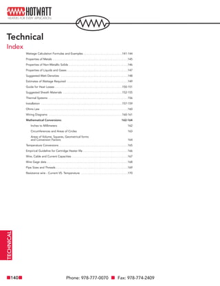
  • 1. Phone: 978-777-0070 Fax: 978-774-2409140 TECHNICAL Technical Index Wattage Calculation Formulas and Examples . . . . . . . . . . . . . . . . . . . . . . . . .141-144 Properties of Metals . . . . . . . . . . . . . . . . . . . . . . . . . . . . . . . . . . . . . . . . . . . . . . . .145 Properties of Non-Metallic Solids . . . . . . . . . . . . . . . . . . . . . . . . . . . . . . . . . . . . . .146 Properties of Liquids and Gases . . . . . . . . . . . . . . . . . . . . . . . . . . . . . . . . . . . . . . .147 Suggested Watt Densities . . . . . . . . . . . . . . . . . . . . . . . . . . . . . . . . . . . . . . . . . . .148 Estimates of Wattage Required . . . . . . . . . . . . . . . . . . . . . . . . . . . . . . . . . . . . . . .149 Guide for Heat Losses . . . . . . . . . . . . . . . . . . . . . . . . . . . . . . . . . . . . . . . . . . .150-151 Suggested Sheath Materials . . . . . . . . . . . . . . . . . . . . . . . . . . . . . . . . . . . . . .152-155 Thermal Systems . . . . . . . . . . . . . . . . . . . . . . . . . . . . . . . . . . . . . . . . . . . . . . . . . . .156 Installation . . . . . . . . . . . . . . . . . . . . . . . . . . . . . . . . . . . . . . . . . . . . . . . . . . . .157-159 Ohms Law . . . . . . . . . . . . . . . . . . . . . . . . . . . . . . . . . . . . . . . . . . . . . . . . . . . . . . .160 Wiring Diagrams . . . . . . . . . . . . . . . . . . . . . . . . . . . . . . . . . . . . . . . . . . . . . . .160-161 Mathematical Conversions: 162-164 Inches to Millimeters 162 Circumferences and Areas of Circles 163 Areas of Volume, Squares, Geometrical forms and Conversion Factors 164 Temperature Conversions . . . . . . . . . . . . . . . . . . . . . . . . . . . . . . . . . . . . . . . . . . . .165 Empirical Guideline for Cartridge Heater life . . . . . . . . . . . . . . . . . . . . . . . . . . . . .166 Wire, Cable and Current Capacities . . . . . . . . . . . . . . . . . . . . . . . . . . . . . . . . . . . .167 Wire Gage data . . . . . . . . . . . . . . . . . . . . . . . . . . . . . . . . . . . . . . . . . . . . . . . . . . . .168 Pipe Sizes and Threads . . . . . . . . . . . . . . . . . . . . . . . . . . . . . . . . . . . . . . . . . . . . . .169 Resistance wire - Current VS. Temperature . . . . . . . . . . . . . . . . . . . . . . . . . . . . . .170
  • 2. Web: www.hotwatt.com Email: sales@hotwatt.com 141 Wattage Calculation Data Basic Heating Formulas The following formulae can be employed in determining wattage capacity required for different materials. Formula A: Wattage required for heat-up = For specific heat and weights of each material being heated, see tables 1, 2, and 3 on pages 145, 146, and 147 Formula B: Wattage losses at operating temperature = Wattage loss/sq. ft. x Area in sq. ft. See curves on pages 150-151. Formula C: Wattage for melting or vaporizing = When the specific heat of a material changes at some temperature during the heat-up, due to melting (fusion) or evaporation (vapor- ization), perform Formula A for heat absorbed from the initial temperature up to the temperature at the point of change, add Formula B, then repeat Formula A for heat absorbed from the point of change to the final operating temperature. See tables 1, 2, and 3 on pages 145-147, for heats of fusion and vaporization and temperatures at which these changes in state occur. Specific Applications For specific applications, substitute the Basic Heat Formulas (A, B, or C above) into the following: To Heat Liquids Wattage for initial heat-up = (a) + Wattage for operating requirements = (a) for new material added + (b) To insure adequate capacity, add 20% to final wattage figures. This will compensate for added losses not readily computed. To Melt Soft Metals Wattage for initial heat-up = (a) to melting point + (c) to melt + (a) to heat above melting point + Wattage for operating requirements = [(a) to melting point + (c) to melt + (a) to heat above melting point] for added material + 11. To insure adequate capacity, add 20% to final wattage figures. This will compensate for added heat losses not really computed. To Heat Ovens Wattage = (a) (for air) + (a) (all material introduced into oven) + (b) Add 25% to cover door heat losses Forced Air Heating Wattage = For explanation of Basic Heat Formulas, see examples on pages 142-144. Weight of material (lbs) x Specific Heat x Temperature Rise ˚F 3.412 x Time (Hours of fraction Thereof) Weight of material (lbs) x Heat of fusion or vaporization (BTU/lb) 3.412 x Heat up time (Hours of fraction Thereof) (b) 2 (b) 2 C.F.M. x temperature rise (˚F) 3 TECHNICAL Technical Wattage Calculation Formulas
  • 3. Phone: 978-777-0070 Fax: 978-774-2409142 TECHNICAL Technical Wattage Calculation Formulas Problem 1: Basic Heating and Heat Loss. A steel mold is being used to form polyethelyne parts. Each hour, 90 ounces of nylon is introduced to the mold. The mold itself measures 10” x 8” x 4”. The mold is attached between two stainless steel platens, each measuring 15” x 12” 11 ⁄2” thick. The platens are insulated from the press mechanism with 1 ⁄2” thick insulation. Operating temperature of the mold is 400˚F and is required to reach this temperature in 1 hour with an ambient temperature of 70˚F. 1) From Table 1, page 145: Specific heat of steel - .12/BTU/lb ˚F 2) From Table 1, page 145: Specific heat of stainless steel - .12/BTU/lb ˚F 3) From Table 2, page 146: Specific heat of polyethelyne - .55/BTU/lb ˚F 4) From Graph 1, page 150: Heat losses curves – A + B @ 400˚F 5) From Table 1, page 145: Converting cubic inches into pounds (density lb/cu. in.) Formula A: Wattage required for heat-up To heat mold = 2,110 watts To heat Platens = 1,800 watts To heat Polyethelyne = = 300 watts Compensation Factor 20% (2,110 + 1,800 + 300) = 840 watts Total wattage required for Heat-up = 5,050 watts (10” x 8” x 4”) = 320 cu.in. x 2 x .284 = 181.7 (lbs) x .12 BTU/lb ˚F x (400 - 70)˚F 3.412 x 1 (15” x 12” x 11 ⁄2”) = 270 cu.in. x 2 x .286 = 154.5 (lbs) x .12 BTU/lb ˚F x (400-70) ˚F 3.412 x 1 5.6 (lbs) x .55BTU/lb ˚F x (400-70) ˚F 3.412 x 1 90 16 Lower Platen
  • 4. Web: www.hotwatt.com Email: sales@hotwatt.com 143 Formula B: Wattage losses at operating temperature (see graphs on pages 150 and 151). Heat loss from mold (vertical surfaces) = 2 sq. ft. x 350w/sq.ft./hr. = 700 watts Heat loss from platen (vertical surfaces) = 1.1 sq. ft. x 350w/sq.ft./hr. = 385 watts Heat loss from platen (horizontal surfaces, uninsulated) = 1.3 sq. ft. x 250w/sq.ft./hr. = 350 watts Heat loss from platen (insulated surface) 250 watts = 2.5 sq. ft. x 100w/sq.ft./hr. = Compensation factor: 20% (700w + 385w + 350w + 250w) = 340 watts Total wattage losses at operating temperature = 2,025 watts Total wattage required for heat-up = 5,050 watts Total wattage required = 7,075 watts The number of holes in the mold would dictate the number of heaters required. Divided the wattages by the number of heaters will equal the wattage rating of each heater. Problem 2: Paraffin melting An open top uninsulated steel tank: 18” wide, 24” long and 18” deep weighs 140 pounds. This tank contains 168 pounds of paraffin which needs to be heated from 72˚F to 150˚F in 2 1 ⁄2” hours. 1.) From Table 1, page 145: Specific heat of steel - .12 BTU/lb-˚F 2.) From Table 2, page 146: Specific heat of solid paraffin - .70 BTU/lb-˚F 3.) From Table 2, page 146: Melting point of paraffin: -133˚F 4.) From Table 3, page 147: Heat of fusion of paraffin - 63 BTU/lb 5.) From Table 3, page 147: Specific heat of melted paraffin - .71 BTU/lb-˚F 6.) From Graph 5, page 151: Surface loss at 150˚F:70w/sq.ft./hr. 7.) From Graph 1, page 150: Surface loss at 150˚F:55w/sq.ft./hr. Formula A: Wattage required for heat-up To heat tank = 155 watts To heat paraffin = 845 watts To heat melted paraffin (fusion occurs at melting point) = 240 watts Formula C: Wattage for melting or vaporizing Heat of fusion to melt paraffin = 1,245 watts 10” x 4” x 4” + 8” x 4” x 4” 144” 11 ⁄2” x 15” x 4” + 11 ⁄2” x 12” x 4” 144” 15” x 12” x 2” - (10” x 8” x 2”) 144” 15” x 12” x 2” 144” 140lb x .12 BTU/lb-˚F x (150 - 72) 3.412 x 2.5 168lb x .70 BTU/lb-˚F x (133 - 72) ˚F 3.412 x 2.5 168lb x .71 BTU/lb-˚F x (150 - 133) ˚F 3.412 x 2.5 168lb x 63 BTU/lb 3.412 x 2.5 Technical Wattage Calculation Formulas TECHNICAL
  • 5. Phone: 978-777-0070 Fax: 978-774-2409144 TECHNICAL Technical Wattage Calculation Formulas Formula B: Wattage losses at operating temperature (see graphs on pages 150 and 151) Average paraffin surface loss 3sq.ft. x 70w/hr. = 210 watts Total losses 13.5sq.ft. x 55w/hr. = 740 watts Compensation factor 20% (155 + 845 + 239 + 1,245 + 210 + 740) = 685 watts Total wattage required = 4,120 watts In addition to calculating the watts required for initial heat-up and heat losses, operating heat requirements must be calculated. Steel pins, each weighing .175 pounds, are to be placed in a 70 pound steel rack and dip-coated in the melted paraffin. 1,750 pins can be processed per hour with 25 pounds of paraffin. Formula A: Wattage required for heat-up To heat pins and rack = 1,030 watts To heat additional solid paraffin = 310 watts To heat additional melted paraffin (fusion occurs at melting point) = 90 watts Formula C: Wattage for melting or vaporizing Heat of fusion, to melt additional paraffin = 460 watts Formula B: Wattage losses at operating temperature (see graphs on pages 150 and 151). Paraffin surface loss 3sq.ft. x 70w/sq.ft./hr. = 210 watts Tank surface loss 13.5sq.ft./ x 55w/sq.ft./hr = 740 watts Compensation factor 20% (1,058 + 310 + 90 + 460 + 210 + 740) = 575 watts Total wattage required = 3,415 watts In the above calculations, the heat-up requirement is the greatest, therefore a heater with a wattage rating of 4,120 watts should be used in this application. The recommended watt density on the heater for this application is 16 watts per square inch (see page 148, table 1). (1750 x .175 + 70)lbs/hr x .12BTU/lb/˚F x (150 - 72) ˚F 3.412 x 1 hour 25lbs/hr x .70BTU/lb˚F x (133 - 72) ˚F 3.412 x 1 hour 25lbs/hr x .71BTU/lb˚F x (150-133)˚F 3.412 x 1 hour 25lbs/hr x 63BTU/lb 3.412 x 1 hour
  • 6. Web: www.hotwatt.com Email: sales@hotwatt.com 145 Density Average Thermal Conductivity Latent Heat (at or near room temp.) Specific Heat (at or near room temp.) of Fusion Material (lb/cu.in.) (BTU/lb/˚F) K(BTU/hr./sq.ft./˚F) Melting Point (˚F) (BTU/lb) Aluminum 2024-IT3 .100 .24 840 935 167 Aluminum 1100-00 .098 .24 1540 1190 169 Aluminum 30003 .099 .24 — 1190 167 Antimony .245 .052 — 1166 25 Brass, Yellow .306 .096 830 1710 — Brass, Red .316 .100 — 1877 — Bronze .318 .104 — 1832 75 Copper .322 .095 2680 1981 91.1 Gold .697 .030 — 1945 29 Incoloy 800 .290 .13 80 2475 — Inconel 600 .304 .126 103 2500 — Iron, Cast .260 .12 346 2150 — Iron, Wrought .278 .12 — 2800 — Lead, Solid .410 .032 240 620 11.3 Lead, Liquid .387 .037 108 — — Magnesium .063 .27 1106 1202 160 Monel 400 .319 .11 151 2370 133 Monel 200 .321 .12 436 2615 133 Nickel 200 .321 .12 436 2615 133 Nickel Silver 18%80%NI20%CN .314 .095 — 1931 — Nichrome .303 .11 — 2550 — Platinum .775 .032 — 3224 49 Silver .379 .057 2900 1760 38 Solder 50%Pb 50%SN .323 .051 310 361 17 Steel .284 .122 460 2760 — Stainless Steel 304 .286 .12 105 2550 — Stainless Steel 316 .288 .118 108 2650 — Stainless Steel 430 .275 .11 — 2650 — Tin, Solid .263 .065 455 450 26.1 Tin, Liquid .253 .052 218 — — Titanium 99% .164 .13 112 3035 — Type Metal 85%Pb 15%Sb .387 .040 — 500 14± Table 1: Properties of Metals Technical Properties of Metals TECHNICAL
  • 7. Phone: 978-777-0070 Fax: 978-774-2409146 TECHNICAL Technical Properties of Non-Metallic Solids Density Average Thermal Conductivity (at or near room temp.) Specific Heat (at or near room temp.) Material (lb/cu.in.) (BTU/lb/˚F) K(BTU/hr./sq.ft./˚F) Melting Point (˚F) Asbestos .070 .25± 5.2 — Asphalt .076 .40 5.3 — Brickwork & Masonry .076 .22 3.7 — Beeswax .035 — — 144 Carbon .080 .28 165 6700 Cellulose Acetate .047 .3 to .5 1.2 to 2.3 — Butyrate .043 .3 to .4 1.2 to 2.3 — Delrin .051 .35 1.6 — Glass .101 .161 7.5 — Graphite .075 .20 — — Lava, Grade A .085 — 9± 2912 Mica .102 .21 3.0 — Magnesium, Compacted .112 .209 20 — Nylon .040 .4 1.5 — Paper .034 .45 .62 — Paraffin .032 .70 1.6 133 Phenolic (general) .046 .40 .6 to 1.2 — Porcelain .114 .26 — 3326 Polyethylene .035 .55 2.3 — Polystyrene .038 .32 .7 to 1.0 — Quartz .080 .21 — 3150 Rubber .044 .44 1.1 — Rosin .380 .5 — — Sugar .073 .30 — — Steatite .094 .20 17.5 to 23 2500± Sulfur .075 .175 1.9 246 Teflon .078 .25 1.7 — Vinyl .046 .3 to .5 .8 to 2.0 — Wood, Oak .029 .57 1.1 — Table 2: Properties of Non-Metallic Solids
  • 8. Web: www.hotwatt.com Email: sales@hotwatt.com 147 Density Average (at or near room temp.) Specific Heat Heat of Vaperation Liquids (lb/cu.ft.) (BTU/lb/˚F) Boiling Point (˚F) (BTU/lb) Acetic Acid 20% 64.1 .91 214 ± 810 ± Alcohol (Ethyl) 49.6 .60 173 367 Benzene 56 .45 175 166 Brine (25% NaCL) 74 .81 221 ± 728 ± Caustic Soda (18% NaOH) 74.9 .84 221 ± 795 ± Dowtherm A 66.1 .44 496 42.2 Ether 46 .503 95 160 Ethylene Glycol 70.5 .602 387 — Fish Oil 70.5 .602 387 — Fuel Oil, Bunker C 61 .50 — 145-150 Freon 12 82.7@70psig .23 -21.6 62 Gasoline 48.6 .675 158-194 137 Glue (1 ⁄3 dry glue, 2 ⁄3 water) 69 .895 — — Glycerine 79 .58 554 — Kerosene 51.5 .47 — 108 Mercury 845 .0333 675 117 Milk 64.5 1(approx.) — — Molasses 87.4 .6 — — NaK (78%K) 46.2 .21 1446 — Nitric Acid 7% 64.7 .92 220 ± 918 ± Oil, Cottonseed 60 .47 — — Oil, Machine 58 .40 — — Oil, Olive 58 .471 570 ± — Paraffin (melted) 47.1 .71 1400 63 Petroleum 56 .51 — — Potassium (K) 44.6 .18 — — Sodium (Na) 51.2 .3 1621 1810 Sulfur (melted) — .234 601 652 Thermonal FR-2 90.6 .3 648 ± — Turpentine 54.3 .41 318 123 Vegetable Oil 57.5 .43 ± — — Water 62.3 1.0 212 970 Table 3: Properties of Liquids Density (at or near room temp. and atmospheric pressures) Specific Heat Gasses (lbs/cu.ft.) (BTU/LB/˚F) Air @ 80˚F .073 .240 Air @ 400˚F .046 .245 Ammonia .044 .523 Acetylene .073 .35 Argon .102 .125 Carbon Dioxide .113 .199 Carbon Monoxide .072 .248 Chlorine .184 .115 Hydrochloric Acid .094 .194 Hydrogen .0052 3.39 Methane .041 .528 Nitrogen .072 .248 Oxygen .082 .218 Sulphur Dioxide .172 .152 Water Vapor @ 212˚F .037 .482 Table 4: Properties of Gases Technical Properties of Liquids and Gases TECHNICAL
  • 9. Phone: 978-777-0070 Fax: 978-774-2409148 TECHNICAL Technical Suggested Watt Densities The rates below are recommended watt densities for use with various materials. Safe values vary with operating temperature, flow velocity, and heat transfer rates. In general, the higher the material temperature, the lower the watt density should be, especially those materials which coke or carbonize, such as oils. Watt densities should be low if a material is being heated to a temperature near where the change of state to a vapor occurs (water to steam @212˚F.) since the vapor state has much poorer heat transfer capabilities. Maximum Maximum Operating Watts Per Material being heated Temp. ˚F Sq. In.* Acid Solutions: Acetic 212 40 Chromic (5%) Boiling 40 Citric Boiling 40 Ferric Boiling 40 Chloride (40%) Hydrochloric 150 30 Nitric (50%) Boiling 40 Sulphuric Boiling 30 Alkai & selected oakite cleaning solution 212 40 Asphalt binder, tar, other viscous compounds 200 8 300 7 400 6 500 5 Caustic Soda 2% 210 45 10% 210 25 75% 180 25 Coffee (direct immersion) Boiling 90 Dowtherm A® Flowing at 1ft/sec or more 750 22 Non-flowing 750 10 Ethylene Glycol 300 30 ± Fuel Oils Grades 1 & 2 (Distillate) 200 22 Grades 4 & 5 (Residual) 200 13 Grades 6 & Bunker C (Residual) 160 8 Gasoline, Kerosene 300 20 Glue (heat indirectly using water bath) 100 Liquid ammonia plating baths 50 25 ** Lubrication Oils SAE 10, @ 130˚F 250 22 SAE 20, @ 130˚F 250 22 SAE 30, @ 130˚F 250 22 SAE 40, @ 210˚F 250 13 SAE 50, @ 210˚F 250 13 **Some oils contain additives that will boil or carbonize at low watt densities. Where oils of this type are encountered a watt density test should be made to determine a satisfactory watt density. Maximum Maximum Operating Watts Per Material being heated Temp. ˚F Sq. In.* Metal melting pot 500 to 900 20-27 Mineral oil 200 20 400 16 Molasses 100 2-3 Molten salt bath 800-950 40 Molten tin 600 20 Oil draw bath 600 20 400 24 Paraffin or wax 150 16 Photographic solutions 150 70 Plating solutions: Cadmium plating 40 Chrome plating 40 Copper plating 40 Nickel plating 40 Tin plating 40 Zinc plating 40 Salt Bath 900 30 Sea Water Boiling 90 Sodium cyanide 140 40 Steel tubing cast into aluminum 500 to 750 50 Steel tubing cast into iron 750 to 1000 55 Heat transfer oils 500 22 flowing at 1 ft/sec or more 600 22 650 22 750 15 Tricholretylene 150 20 Vapor degreasing solutions 275 20 Vegetable oil (fry kettle) 400 30 Water (process) 212 60 Water (washroom) 140 80-90 * Maximum watt densities are based on heated length, and may vary depending upon concentration of some solutions. Watt density should be kept as low as possible in corrosive applica- tions since higher watt densities accelerate corrosive attack on element sheaths. Consult factory for limitations.
  • 10. Technical Estimates of Wattage Required Web: www.hotwatt.com Email: sales@hotwatt.com 149 TECHNICAL Lbs. of Steel 25 50 100 150 200 250 300 400 500 600 700 800 900 1000 Temperature Rise F˚ 50˚ 100˚ 200˚ 300˚ 400˚ 500˚ 600˚ Kilowatts to heat in one hour .06 .12 .25 .37 .50 .65 .75 .12 .25 .50 .75 1.00 1.25 1.50 .25 .50 1.00 1.50 2.00 2.50 3.00 .37 .75 1.50 2.25 3.00 3.75 4.50 .50 1.00 2.00 3.00 4.00 5.00 6.00 .65 1.25 2.50 3.75 5.00 6.25 7.50 .75 1.50 3.00 4.50 6.00 7.50 9.00 1.00 2.00 4.00 6.00 8.00 10.00 12.00 1.25 2.50 5.00 7.50 10.00 12.50 15.00 1.50 3.00 6.00 9.00 12.00 15.00 18.00 1.75 3.50 7.00 10.50 14.00 17.50 21.00 2.00 4.00 8.00 12.00 16.00 20.00 24.00 2.25 4.50 9.00 13.50 18.00 22.50 27.00 2.50 5.00 10.00 15.00 20.00 25.00 30.00 Kilowatt Hours to Heat Steel A 20% Safety Factor is included to compensate for high heat loss- es and/or low voltage. .66 5 1.3 10 2.0 13 2.7 20 3.3 25 4.0 30 5.3 40 6.7 50 8.0 60 9.4 70 10.7 80 12.0 90 13.4 100 16.7 125 20.0 150 23.4 175 26.7 200 33.7 250 40 300 53.4 400 66.8 500 Temperature Rise F˚ 20˚ 40˚ 60˚ 80˚ 100˚ 120˚ 140˚ Kilowatts to heat in one hour 0.3 0.5 0.8 1.1 1.3 1.6 1.9 0.5 1.1 1.6 2.1 2.7 3.2 3.7 0.8 1.6 2.4 3.2 4 4.8 5.6 1.1 2.2 3.2 4.3 5.3 6.4 7.5 1.3 2.7 4 5.3 6.7 8 9.3 1.6 3.2 4.8 6.4 8 9.6 12 2.1 4 6.4 8.5 11 13 15 2.7 5.4 8 10.7 13 16 19 3.3 6.4 9.6 12.8 16 19 22 3.7 7.5 11.2 15 19 22 26 4.3 8.5 13 17 21 26 30 5 10 14.5 19 24 29 34 5.5 11 16 21 27 32 37 7 13 20 27 33 40 47 8 16 24 32 40 48 56 9 18 28 37 47 56 65 11 21 32 43 53 64 75 13 27 40 53 67 80 93 16 32 47 64 80 96 112 21 43 64 85 107 128 149 27 53 80 107 133 160 187 Kilowatt Hours to Heat Water Amount of Liquid Cubic Ft. Gallons .5 3.74 1 7.48 2 14.96 3 22.25 4 29.9 5 37.4 10 74.8 15 112.5 20 149.6 25 187 30 222.5 35 252 40 299 45 336.5 50 374 55 412 60 449 65 486 70 524 75 562 Temperature Rise F˚ 50 100 200 300 400 500 .3 .5 1 2 2 3 .5 1 2 3 4 6 1 1 2 4 6 11 2 3 6 9 12 16 2 4 8 12 16 22 3 4 9 15 20 25 5 9 18 29 40 52 7 14 28 44 60 77 9 18 37 58 80 102 11 22 46 72 100 127 13 27 56 86 120 151 16 31 65 100 139 176 18 36 74 115 158 201 20 40 84 129 178 226 22 45 93 144 197 252 25 49 102 158 217 276 27 54 112 172 236 302 29 58 121 186 255 326 32 62 130 200 275 350 34 67 140 215 294 375 Kilowatt Hours to Heat Oil Amount of Oil Cubic Ft. Gallons Add 5% for uninsulated tanks. A 20% Safety Factor is included to compensate for high heat losses and/or low voltage.
  • 11. Phone: 978-777-0070 Fax: 978-774-2409150 TECHNICAL Technical Guide for Heat Losses 2400 2200 2000 1800 1600 1400 1200 1000 800 600 400 200 200 300 400 500 600 700 800 900 WattsPerSquareFoot Temperature ˚F Graph 1: Losses from Uninsulated Metal Surfaces. A-Oxidized Steel B-Oxidized Steel C-Oxidized Steel A-Oxidized Aluminum B-Oxidized Aluminum C-Oxidized Aluminum Semi-Dull Copper 1600 1500 1400 1300 1200 1100 1000 900 800 700 600 500 400 300 200 100 50 80 90 100 110 120 130 140 150 160 170 180 190 200 210 WattsPerSquareFootofWaterSurface Temperature of Water ˚F Graph 2: Losses from Open Hot Water Tanks 2 F.P.S. 40% Relative Humidity 1 F.P.S. 40% Relative Humidity 2 F.P.S. 60% Relative Humidity 1 F.P.S. 60% Relative Humidity Curves “A” show heat losses from vertical surfaces of tanks, pipes, etc. and also top surface losses from a horizontal surface laid flat. Curves “B” show average heat losses from top and bottom surfaces of a horizontal surface laid flat. Curves “C” show heat losses from bottom surface of a horizontal sur- face laid flat. All curves presuppose still air (approx. one foot per second) at 70˚F.
  • 12. Web: www.hotwatt.com Email: sales@hotwatt.com 151 1200 1100 1000 900 800 700 600 500 400 300 200 100 300 400 500 600 700 800 900 WattsPerSquareFoot Temperature ˚F Graph 3: Losses from Molten Metal Surfaces. 90 80 70 60 50 40 30 20 10 5 0 100 200 300 400 500 600 700 800 900 1000 WattsPerSquareFoot Temperature Difference ˚F Graph 4: Losses through Insulated Walls (ovens, pipes, etx.) 2”Thickness of Insulation 3”Thinkness of Insulation 4”Thickness of Insulation 1000 900 800 700 600 500 400 300 200 100 0 70 100 200 300 400 500 600 WattsPerSquareFoot Temperature of Oil or Paraffin ˚F Graph 5: Losses from Surfaces of Oil Baths. Technical Guide for Heat Losses TECHNICAL
  • 13. Phone: 978-777-0070 Fax: 978-774-2409152 TECHNICAL Technical Suggested Sheath Materials The following table of recommendations should only be used as a guide. The proper choice should be based upon your knowledge of the conditions which exist in each application. Iron Cast Iron 300 Series Inconel Compound Copper Lead Aluminum Nickel and Steel NI Resist Stainless Monel Incoloy Acetic Acid, Crude 2 x 2 2 x 3 2 2 3 Pure 2 2 1 2 — x — 1 3 Vapors 2 x 3 2 — x — 2 3 150 PSI; 400˚F 2 x 3 2 — — — 2 3 Acetone — — — — 3 2 1 — — Alboloy Process — — — — 1 — — — — Aluminum Sulphate 2 1 3 3 x 3 2 2 — Ammonia Gas Cold 3 1 1 — 1 1 1 1 — Hot x x — — 3 3 3 3 — Ammonia and Oil — — — — 1 — — — — Ammonium Chloride x 1 x 2 3 1 2 2 — Ammonium Hydroxide x 1 2 — 1 1 1 3 1 Ammonium Nitrate x x 2 — 1 3 1 3 — Ammonium Sulphate 2 1 — — 1 1 1 1 — Amyl Alcohol 1 — — — — — — 1 — Anhydrous Ammonia x — — — 1 — — — — Aniline, Aniline Oil x — x — 1 — 1 1 — Aniline Dyes — — — — — — 1 1 — Anodizing Solutions 10% — — — — 3 — 1 — — Chromic Acid 96˚F — — — — 3 — 1 — — Sulphuric Acid 70˚F — 1 — — — — — — — Sodium Hydroxide Alkaline — — — — 1 — — — — Nigrosine Black Dye — — — 2 — — — 1 — Nickel Acetate — 3 — 2 — — — 1 — Barium Hydroxide x x x 1 — — 1 — — Barium Sulphide x 1 — — — — 1 1 — Bleaching Solution — — — 2 — — — 1 — 11 ⁄2lb. Oxalic Acid per Gallon of H2O at 212˚F — — — — — — — — — Bonderizing — — — — 3 2 1 — — Cadmium Plating — — — — — — — — 1 Carbolic Acid, Phenol x 1 1 — 3 3 1 1 1 Carbon Dioxide Dry 1 1 1 — 1 1 1 1 1 Wet 2 x 2 — 2 3 1 1 1 Carbon Tetrachloride 3 2 3 — 3 3 3 1 1 Castor Oil — — 1 — 1 — 1 1 1 Chloroacetic Acid x x x 2 x — x — — Chlorine Dry 1 1 1 — 1 1 1 1 — Wet x 2 x — x x x x — Chromic Acid x 1 x — 3 3 1 2 3 Chrome Plating — 1 — — — — — — — Citric Acid 1 1 1 — x 3 1 1 1 Cobalt Acetate 130˚F — — — — — — — 1 1 Coconut Oil — — — 1 — — — 2 — Copper Chloride 3 1 x — 2 — x 2 — Copper Cyanide — — — — 1 — — — — Copper Plating — — — — 1 — — — — Copper Sulphate 3 1 x — x 3 1 1 1 Creosote 1 — 1 — 1 1 1 1 — Resistance Ratings: 1 = Good 2 = Fair 3 = Depends on Conditions x = Unsuitable
  • 14. Web: www.hotwatt.com Email: sales@hotwatt.com 153 Iron Cast Iron 300 Series Inconel Compound Copper Lead Aluminum Nickel and Steel NI Resist Stainless Monel Incoloy Deoxidine — — — — — — 1 — — Deoxylyle — — — — — — 1 — — Dipenyl 300˚ - 350˚F — — — — 1 — — — — Di Sodium Phosphate 25% 180˚F — — — — 1 — — — — Diversey No. 99 — — — — 1 — — — — Downtherm — — — — 1 — — — — Ethers 1 1 1 — 1 — — 1 1 Ethyl Chloride 1 — — 1 1 — 1 1 — Ethylene Gycol 300˚F — — — — — — 1 1 — Ferric Chloride x x x x x x x x x Ferric Sulphate x 1 x x x x 2-304 x 3 — — — — — — 1-316 — — Formaldehyde 2 x 2 — 2 2 1 1 1 Formic Acid 2 x x 3 x — 2 3 3 Freon 1 1 1 — 3 1 3 1 — Fuel Oil 1 1 — — 1 — 1 1 — Fuel Oil, Acid 3 1 — — 3 — 3 1 — Gasoline, Sour 3 1 3 — 3 3 1 1 1 Gasoline, Refined 1 1 1 — 1 1 1 1 1 Glycerin, Glycerol 2 1 1 — 1 1 1 1 — Holdens 310A Tempering Bath — — — 1 — — — — — Houghtons Mar Tempering Salt — — — 3 3 — — — — Hydrochloric Acid < 150˚F x 2 x 3 x x x 3 — > 150˚F x x x 3 x — x 3 — Hydrofluoric Acid Cold < 65% 3 2 x x x x x 2 — > 65% 2 3 x — 2 — x 1 — Hot < 65% x x x x x — x 3 — > 65% 2 x x — 3 — x 1 — Hydrogen Peroxide x 2 1 2 x x 1 2 1 Irdite 1-part and 5-parts water 200˚F — 1 — — — — — — — Isoproponel 2 — — — 3 — — 1 — Kerosene 1 1 — — 1 — 1 1 1 Kolene — — — 1 — — — — — Lacquer solvents 3 — 1 — 3 1 1 1 — Lard — — — — 2 — — — — Linseed oil 1 1 1 — 1 — 1 1 1 Magnesium chloride 2 x x 2 2 2 2 2 — Magnesium hydroxide x — x 1 1 1 1 1 — Magnesium sulphate 1 — 2 — 1 1 1 1 — Mercuric chloride x — x x 3 3 x x x Mercury x — x — 1 1 1 1 1 Methyl alcohol, methanol 1 1 1 — 1 — 1 1 — Methyl chloride 1 1 — 1 1 — — 1 — Mineral oils 1 1 1 — 1 — 1 1 1 Naphthalene — — — — 1 — — — — Nickel chloride x — x — — — 2 3 — Nickel plating, bright — 1 — — — — — — — Nickel plating, dull — 1 — — — — — — — Nickel sulphate x — x — — — 1 3 x Nitric acid, Crude x x 3 x x — 3 x x Concentrated x x 1 x x — 2 x x Diluted x x x x x — 1 x x Resistance Ratings: 1 = Good 2 = Fair 3 = Depends on Conditions x = Unsuitable Technical Suggested Sheath Materials (con’t) TECHNICAL
  • 15. Phone: 978-777-0070 Fax: 978-774-2409154 TECHNICAL Technical Suggested Sheath Materials (con’t) Iron Cast Iron 300 Series Inconel Compound Copper Lead Aluminum Nickel and Steel NI Resist Stainless Monel Incoloy Nitrbenzene 2 — — — 1 — 1 — — Oakite No. 20 — — — — 1 — — — — Oakite No. 23 — — — — 1 — — — — Oakite No. 24 — — — — 1 — — — — Oakite No. 30 — — — — 1 — — — — Oakite No. 32 — — — — — — — — — Oakite No. 33 — — — — — 1-347 — — — Oakite No. 36 — — — — — — — — — Oakite No. 51 — — — — 1 — — — — Oakite No. 90 @ 180˚F — — — — 1 — — — — Oleic acid x x 1 1 3 3 1 1 1 Oxalic acid 3 x 1 — 3 3 3 1 — Paraffin — — — — 1 — — — — Parkerizing — — — — 3 2 1 — — Perchlorethylene — — — — — — 1 — — Permachlor — — — — — — 1 — — Petroleum oils, crude <500˚F 3 3 1 3 1 1 1 3 — >500˚F x x 1 x 1 1 1 x — <1000˚F x x x x x — 3 x — — — — — — — 1-347 — — Phenol 85%, 120˚F — — — 1 3 — 1 — — Phosphoric acid Crude x 3 x x 3 — 3 x — Pure <45% 2 1 3 3 x — 1 2 — >45% Cold 2 1 x 3 x — 1 2 — >45% Hot 3 x x — x — x-304 3 — — — — — — — 3-316 — — Photo fixing bath — — — — — — 1 3 — Picric acid water solution x x x x 3 — 1 3 — Potassium chloride 1 1 3 1 1 1 1 1 — Potassium cyanide x x x — 1 — 1 1 — Potassium dichromate 208˚F — — — — — — 1-347 — — Potassium hydroxide x x x 1 3 1 2 1 — Potassium sulphate 1 1 1 1 1 1 2 1 — Prestone 350˚F — — — — 1 — — 1 — R5 Bright Dip for copper polish @ 180˚F — — — — — — 1-316 — — Soap solutions 3 1 — — 1 1 1 1 — Sodium carbonate <20% — — — — 1 — — — — Sodium chloride 2 1 x 1 1 1 2-304 1 1 — — — — — — 1-316 — — Sodium cyanide x x x — 1 3 1-316 2 — Sodium hydroxide x 2 x 1 1 1 2 1 1 Sodium hypochlorite 3 x x 3 x 3 x 3 — Sodium nitrate 2 1 1 1 1 1 2-304 1 1 — — — — — — 1-316 — — Sodium peroxide — — 1 1 3 1 1 1 — Sodium silicate 3 x x 1 1 1 1-316 1 — Sodium sulphate 1 1 3 1 1 1 1 1 1 Sodium sulphide x 1 x 2 1 1 1 2 1 Soybean oil — — — — — — 1 — — Steam <500˚F 1 3 1 1 1 — 1 1 1 500-1000˚F 3 x 3 3 3 — 1 3 1 >1000˚F x — x x x — 1 x 1 Stearic acid 3 1 3 1 3 3 1 1 1 Resistance Ratings: 1 = Good 2 = Fair 3 = Depends on Conditions x = Unsuitable
  • 16. Web: www.hotwatt.com Email: sales@hotwatt.com 155 Iron Cast Iron 300 Series Inconel Compound Copper Lead Aluminum Nickel and Steel NI Resist Stainless Monel Incoloy Sulphur x — 1 x 1 3 2 x 1 Sulphuric acid<10% Cold 3 1 3 3 x — 2 3 — Hot x 1 3 x x — 2-316 3 — — — — — — — x-304 — — 10-75% Cold x 1 3 3 x — x-304 3 — — — — — — — 2-316 — — Hot x 1 x x x — x 3 — 75-95% Cold x 1 3 3 3 — 1 3 — Hot x 1 x x 2 — x 3 — Fuming x 1 3 x 3 2 3-304 x — — — — — — — 2-316 — — Sulphurous acid 3 1 3 x 1 — 3-316 x — — — — — — — x-304 — — Tannic acid 1 x x 1 — — 2 1 — Tar — — 1 — 1 — 1 — 1 Tartaric acid — 1 1 3 — — 3-304 3 — — — — — — — 1-316 — — Tetrachlorethylene — — — — 1 — — — — Thermoil GranodineTM — — — — 2 — — — — TherminolTM Fr. 1-8-12W/Sq.In.640˚F — — — — 1 — — — — Tin plating — — — 1 — — — — — Toluene — 1 1 — 1 — 1 1 — Triad solvent — — — — 3 — — — — Trichloroethylene 3 2 3 — 3 3 3 1 — Turco No. 2623 — — — — 1 — — — — Turpentine 3 1 1 — 3 1 1 1 — Urea ammonia liquor 48˚F — — — — 1 — — — — Vegetable oil — — — — — — 1 — — Vinegar — — 3 — 3 — 2-304 1 — — — — — — — 1-316 — — Water, acid mine containing oxidizing salts 3 3 3 3 x 3 1 x — no oxidizing salts — — 1 — 3 1 x 1 — Water, fresh 1 1 1 — 3 1 1 1 1 Distilled, Lab grade x x 1 1 x x 1 3 1 Return condensate 1 1 1 — 1 1 1 1 1 Water, sea water 3 1 x — 3 1 2 1 2 Whiskey and wines 1 — — — x 3 2-304 1 1 — — — — — — 1-316 — — X-ray solution — — — — — — 1 — — Zinc chloride x 1 x — 3 3 x 1 — Zinc plating — — — — 1 — — — — Zinc sulphate x — 3 — 3 1 1 1 1 Resistance Ratings: 1 = Good 2 = Fair 3 = Depends on Conditions x = Unsuitable Because so many Factors are beyond our Power to control we cannot be responsible for any electric immersion heater failure that can be attributed to corrosion. This is in view of any warranties, written or verbal, relative to heater performance in a corrosive environment. Technical Suggested Sheath Materials (con’t) TECHNICAL
  • 17. Phone: 978-777-0070 Fax: 978-774-2409156 TECHNICAL Technical Thermal Systems Thermal Systems The result obtained with a precision temperature controller, as with any tool, depend upon how skillfully it is used. Close temperature control can be maintained only if the thermal system is properly designed so that it responds quickly and accurately to operating conditions. Thermal systems have four elements, all of which contribute to systems control performance. They are: 1. WORK (or load) — the material or product which must be maintained at a controlled temperature; 2. HEAT SOURCE — the device which delivers the heat used by the system, such as gas, oil, or electric heaters; 3. HEAT TRANSFER MEDIUM — the material which transmits the heat from the heat source to the work; 4. CONTROLLER — the instrument which controls the heat flow on the basis of the difference between sensed temperature and controller’s set point. In addition, careful consideration must be given to the physical make-up of the system. The proper location of heat sensor and work-load, a good selection of the heat transfer medium, and use of reliable components are all essential to the development of a good thermal system. Although in practice, thermal systems are not purely steady or variable, they usually are predominantly one or the other. For basic system design, the following rule of thumb will be helpful: where the heat demand is relatively steady, the sensing element of the controller should be placed close to the heat source; where the demand is largely variable, it should be near the work area. A complicated system may require several different sensing element locations before a suitable one is found. One should always remember, however that the element should be closer to the area where a temperature change must be sensed with minimum thermal lag. (Thermal lag is the delay in heat transfer from place to place in the thermal system). The effect of various sensing element locations on the control of predominantly static or dynamic systems is clearly illustrated in Fig. 1. Fig 2 applies to liquid and gas systems which require additional considerations. Because the heat demand is basically steady, the sensing element should normally be located close to and above the heat source to minimize system bandwidth. (Bandwidth is the total temperature variation above and below the average operating temperature measured at some point in the system). Fig. 3: Close grouping of heater, sensing element and work. Where this layout is feasible, it gives excellent control under most conditions and is desirable when the thermal load changes frequently. The heat transfer paths from he work and heater to the thermostat are short, so that thermal lag is slight. System inertia is low because of the small mass of heat transfer medium. Rapid cycling will hasten recovery of the system from thermal upsets. Fig. 4: Thermostat between heater and load. This is a “general purpose” arrangement for installations where the heat demand my be alternately steady and variable. By being midway between them, the sensing element can respond to changes at the work and the heater without excessive lag in either instance. Fig. 5: Heater at load, thermostat distant. This arrangement practically guarantees poor control. The sensing element is too far from either the heater or the load to respond to temperature changes from either one without excessive lag. The arrangement is presented primarily to emphasize that, unless you are careful in placing the element, the controller may find it impossible to maintain even fair control. Temperature of the Load
  • 18. Web: www.hotwatt.com Email: sales@hotwatt.com 157 Cartridge/Superwatt Heater The most important thing to remember about the installation of a cartridge heater is that the cartridge should be a close fit in the hole into which it is inserted. This results in fast heat transfer to the sur- rounding material and aids in keeping the element as cool as pos- sible for long life. Cartridge units are made with special tubing which is a few thou- sandths undersize to insure a free fit for easy installation. To install cartridge heaters, drill and ream holes to proper length and the nominal diameter plus .001” maximum minus .000” of the cartridge heater (3 ⁄16”, 3 ⁄8”, 1 ⁄2”, 5 ⁄8”, etc.) For example, a 1 ⁄2” cartridge heater actually measures .497” diameter. A hole should be drilled and reamed to 1 ⁄2” diameter + .001” – .000” to insure proper fit. Always finish-ream drilled or cast holes to insure smooth, uniform metal to metal contact. A knockout hole (Fig. 1) should be provided if possi- ble to facilitate cartridge removal. The receptacle hole should be free from oil before cartridge installation to avoid contamination and shorter heater life. Fig. 1 If there is danger of a heater slipping from its hole, it should be held in place with metal clips (Fig 2). Fig. 2 Do not use set screws to hold cartridge heaters in place. Lead wires, especially when the heater is used in a moving die or platen, should be supported (Fig. 3) or protected with a lead spring (Fig. 4) See SF5 on page 22. Fig. 3 On many applications plastic material, machine oil, and/or Moisture may be present. Cycling of a cartridge heater causes these materials to be absorbed. Heaters, therefore, should be carefully selected for these applications utilizing protective conduit for leads and if necessary, hermetic sealing for long heater life. Theses extras are available form the factory at a nominal additional charge (See pages 22-27). Square/Rectangular Heaters Technical Installation TECHNICAL
  • 19. Phone: 978-777-0070 Fax: 978-774-2409158 TECHNICAL Strip Heaters Strip heaters are designed for contact heating and therefore must be tightly clamped to the object to be heated to keep the heater from expanding away from the surface. Care should be taken to see that the heaters are placed squarely against the surface to be heat- ed. Air gaps between the heater surface and the heater will result in poor heat transfer and shorter heater life. Mounting Strip Heaters should be firmly clamped with heavy metal strips. These should be arranged across the heater (or heaters) so that there will be bolts on each side of the heater. These bolts should be spaced approximately 3 to 4 inches apart (Fig 1). Use heaters with mounting holes only in air-heating applications, and only when nec- essary. The reason for this is that the heater heats up, it expands away from the surface to be heated causing air gaps and poor heat transfer. Using Mounting Holes When strip heaters are fastened to the object to be heated utilizing mounting holes or used as an air heater, the screws that are used for mounting should be provided with lock washers and should not be drawn up tightly because the strip heater should be free to expand. Unit lengths beyond 24” may require special mounting to allow for expansion. Consult factory. Band Heaters Band heaters should be clamped securely to the object to be heat- ed. They should be mounted so that they are not tilted in assembly, but are placed squarely against the surface to be heated. Air gaps as a result of poor clamping, result in poor heat transfer, excessive heat loss, and short heater life. (Fig 2.) Band heaters should be clamped securely and squarely to the sur- face to be heated, run at operating temperature and retightened to correct for the effects of expansion. Technical Installation
  • 20. Web: www.hotwatt.com Email: sales@hotwatt.com 159 Technical Installation Installation in air Ducts: Finned strips and duct heater 1. Locate regulating thermostat on downstream side of heater near the top of the duct. 2. Mount heater with terminals at the duct bottom to prevent overheating. 3. As a safety feature in the event of abnormal temperatures or safe- ty requirements, it is suggested to use a thermal cutout in conjunction with thermostatic control, or by itself when no thermostat is used. Oven Heating (Stainless Steel Strip Heaters): 1. When mounting strip heaters in an oven, allow for expansion and contraction by loosely bolting one mounting tab and securing the other tab firmly. 2. Mount the strip with the terminals at the bottom or cooler part of the oven. 3. In a forced air system, the width of the strip should be parallel to the direction of the air flow. 4. Mount strips on edge in horizontal installation across the bottom and along the sides of the oven, allowing 3” minimum air space between the heaters and the bottom of the ovens wall to allow for proper circulation of heated air. For large ovens, allow greater clearance areas. 5. In horizontal mounting, install a protective screen or grill above the strips at the bottom of the oven. 6. Support strips on 36” centers to prevent sagging. TECHNICAL
  • 21. Phone: 978-777-0070 Fax: 978-774-2409160 TECHNICAL Technical Ohms Law and Wiring Diagrams Ohms Law E = Volts, W = Watts, I = Amperes, R = Ohms To Determine Watts (W) : Wiring Diagrams Fig. 1: 120V or 240V single phase two or more heaters in parallel with thermostat rating adequate for line voltage and current Fig. 2: 240V or 480V three phase deltas (three phase wye) with thermostat adequate for line voltage and current Fig. 3: 120V, 240V, 480V single phase two or more heaters in series with thermostat rating adequate for line voltage and current Fig. 4: Two or more heaters wired in parallel with thermostat not adequate for line current (or voltage) To Determine Volts (E): To Determine Ohms (R): To Determine Amperes (I): Variation of Wattage with Voltage Change = New Voltage = Original Heater Voltage = Original Wattage = New Wattage 200 180 160 140 120 100 80 60 40 20 0 20 40 60 80 100 120 140 160 180 200 PercentWattage Per cent Volts Percentage Variation of Voltage vs. Wattage
  • 22. Web: www.hotwatt.com Email: sales@hotwatt.com 161 Wiring Diagrams Fig. 5: Two or more heaters wired in parallel in each leg of a 3 phase delta circuit. Thermostat rating not adequate for line current or voltage. Fig. 6: Single phase or three phase AC only with properly rated SCR power control with thermocouple input temperature controller. Fig. 7: Special circuit for switching from parallel operation in a 3 phase delta circuit to a pair in series operation, with both contractors closed. Circuit operates at full power at element rated voltage. With either #1 or #2 contractor open, circuit operates at 1 ⁄4 power, with voltage across each element at 1 ⁄2 rated voltage. Heater element wattages must be equal to give balanced 3 phase circuit for both circuits. Fig. 8: Circuit for switching from a 3 phase delta circuit for full power to a 3 phase wye circuit at 1 ⁄3 power. Watt density of heaters is also dropped to 1 ⁄3 of original. Technical Wiring Diagrams (con’t) TECHNICAL
  • 23. Phone: 978-777-0070 Fax: 978-774-2409162 TECHNICAL Technical Mathematical Conversions Inches Fraction Decimals Millimeters .00004 .001 .13780 3.5 19 ⁄32” .59375 15.0812 1.57480 40 .00039 .01 9 ⁄64” .14063 3.5719 .600 15.24 1.65354 42 .00079 .02 .150 3.810 39 ⁄64” .60938 15.4781 13 ⁄4” 1.750 44.45 .001 .025 5 ⁄32” .15625 3.9688 .61024 15.5 1.77170 45 .00118 .03 .15748 4 5 ⁄8” .6250 15.875 1.88976 48 .00157 .04 11 ⁄64” .17188 4.3656 .62992 16 1.96850 50 .00197 .05 .1750 4.445 41 ⁄64” .64063 16.2719 2” 2.000 50.8 .002 .051 .17717 4.5 .64961 16.5 2.04724 55 .00236 .06 3 ⁄16” .18750 4.7625 .650 16.51 2.16540 53 .00276 .07 .19685 5 21 ⁄32” .65625 16.6688 2.20472 56 .003 .0762 .20 5.08 .66929 17 21 ⁄4” 2.250 57.15 .00315 .08 13 ⁄64” .20313 5.1594 43 ⁄64” .67188 17.0656 2.36220 60 .00354 .09 .21654 5.5 11 ⁄16” .68750 17.4625 21 ⁄2” 2.500 63.5 .00394 .1 7 ⁄32” .21875 5.5562 .68898 17.5 2.51968 64 .004 .1016 .2250 5.715 .700 17.78 23 ⁄4” 2.750 69.85 .005 .1270 15 ⁄64” .23438 5.9531 45 ⁄64” .70313 17.8594 2.83464 72 .006 .1524 .23622 6 .70866 18 2.95280 75 .007 .1778 1 ⁄4” .250 6.35 23 ⁄32” .71875 18.2562 3” 3.000 76.2 .00787 .2 .25591 6.5 .72835 18.5 3.14960 80 .008 .2032 17 ⁄64” .26563 6.7469 47 ⁄64” .73438 18.6531 31 ⁄2” 3.500 88.9 .009 .2286 .275 6.985 .74803 19 3.54330 90 .00984 .25 .27559 7 3 ⁄4” .750 19.050 3.9370 100 .01 .254 9 ⁄32” .28125 7.1438 49 ⁄64” .76563 19.4469 4” 4.000 101.6 .01181 .3 .29528 7.5 .76772 19.5 4.33070 110 1 ⁄64” .01563 .3969 19 ⁄64” .29688 7.5406 25 ⁄32” .78125 19.8438 41 ⁄2” 4.500 114.3 .01575 .4 .30 7.62 .78740 20 4.72440 120 .01969 .5 5 ⁄16” .3125 7.9375 51 ⁄64” .79688 20.2406 5” 5.000 127 .02 .508 .31496 8 .800 20.320 5.51180 140 .02362 .6 21 ⁄64” .32813 8.3344 .80709 20.5 5.90550 150 .025 .635 .33465 8.5 13 ⁄16” .81250 20.6375 6” 6.000 152.4 .02756 .7 11 ⁄32” .34375 8.7312 .82677 21 6.29920 160 .0295 .75 .350 8.89 53 ⁄64” .82813 21.0344 7.08660 180 .03 .762 .35433 9 27 ⁄32” .84375 21.4312 7.8740 200 1 ⁄32” .03125 .7938 23 ⁄64” .35938 9.1281 .84646 21.5 8” 8.000 203.2 .0315 .8 .37402 9.5 .850 21.590 8.66140 220 .03543 .9 3 ⁄8” .375 9.526 55 ⁄64” .85938 21.8281 9.44880 240 .03937 1 25 ⁄64” .39063 9.9219 .86614 22 9.84250 250 .04 1.016 .39370 10 7 ⁄8” .875 22.225 10” 10.000 254 3 ⁄64” .04687 1.191 .400 10.16 .88583 22.5 10.23620 260 .04724 1.2 13 ⁄32” .40625 10.3188 57 ⁄64” .89063 22.6219 11.02360 280 .05 1.27 .41339 10.5 .900 22.860 11.8110 300 .05512 1.4 27 ⁄64” .42188 10.7156 .90551 23 12 (1 ft.)” 12.000 304.8 .05906 1.5 .43307 11 29 ⁄32” .90625 23.0188 12.59840 320 .06 1.524 7 ⁄16” .43750 11.1125 59 ⁄64” .92188 23.4156 13.38580 340 1 ⁄16” .06250 1.5875 .450 11.430 .92520 23.5 13.77950 350 .06299 1.6 .45276 11.5 15 ⁄16” .93750 23.8125 14.17320 360 .06693 1.7 29 ⁄64” .45313 11.5094 .94488 24 14.96090 380 .07 1.778 15 ⁄32” .46875 11.9062 .950 24.130 15.7480 400 .07087 1.8 .47244 12 61 ⁄64” .95313 24.2094 16” 16.000 406.4 .075 1.905 31 ⁄64” .48438 12.3031 .96457 24.5 17.71650 450 5 ⁄64” .07813 1.9844 .49213 12.5 31 ⁄32” .96875 24.6062 19.6850 500 .07874 2 1 ⁄2” .50 12.7 .98425 25 20” 20.000 508 .08 2.032 .51181 13 63 ⁄64” .98438 25.0031 23.6220 600 .08661 2.2 33 ⁄64” .51563 13.0969 1 1.00000 25.4 2 Feet 24.000 609.6 .09 2.286 17 ⁄32” .53125 13.4938 1.06229 27 3 Feet 36.000 914.4 .09055 2.3 .53150 13.5 1.10240 28 39.370 1 Meter 3 ⁄32” .09375 2.3812 35 ⁄64” .54688 13.8906 1.18110 30 4 Feet 48.000 1,219.2 .09843 2.5 .550 13.970 11 ⁄4” 1.250 31.75 5 Feet 60.000 1,524.0 .1 2.54 .55118 14 1.29921 33 6 Feet 72.000 1,828.8 .10236 2.6 9 ⁄16” .56250 14.2875 1.3780 35 78.740 2 Meters 7 ⁄64” .10937 2.7781 .57087 14.5 1.41732 36 8 Feet 96.000 2,438.4 .11811 3 37 ⁄64” .57813 14.6844 11 ⁄2” 1.500 38.1 118.110 3 Meters 1 ⁄8” .1250 3.175 .59055 15 1.53543 39 196.850 5 Meters Inches Fraction Decimals Millimeters Inches Fraction Decimals Millimeters Inches Fraction Decimals Millimeters Inches to Millimeters To convert to millimeters: Multiply Inches x 25.4 To convert to inches: Multiply millimeters x .03937
  • 24. Web: www.hotwatt.com Email: sales@hotwatt.com 163 Circumferences and Areas of Circles. Diameter Circumference Area Diameter Circumference Area Diameter Circumference Area 1 ⁄64 0.0491 0.0002 2 6.2832 3.1416 5 15.7080 19.635 1 ⁄32 0.0982 0.0008 21 ⁄16 6.4795 3.3410 51 ⁄16 15.9043 20.129 1 ⁄16 0.1963 0.0031 21 ⁄8 6.6759 3.5466 51 ⁄8 16.1007 20.629 8 ⁄32 0.2945 0.0069 23 ⁄16 6.8722 3.7583 53 ⁄16 16.2970 21.135 1 ⁄8 0.3927 0.0123 21 ⁄4 7.0686 3.9761 51 ⁄4 16.4934 21.648 5 ⁄32 0.4909 0.0192 25 ⁄16 7.2649 4.2000 55 ⁄16 16.6987 22.166 3 ⁄16 0.5890 0.0276 23 ⁄8 7.4613 4.4301 53 ⁄8 16.8861 22.691 7 ⁄32 0.6872 0.0376 27 ⁄16 7.6576 4.6664 57 ⁄16 17.0824 23.221 1 ⁄4 0.7854 0.0491 21 ⁄2 7.8540 4.9087 51 ⁄2 17.2788 23.758 9 ⁄32 0.8836 0.0621 29 ⁄16 8.0503 5.1572 59 ⁄16 17.4751 24.301 5 ⁄16 0.9817 0.0767 25 ⁄8 8.2467 5.4119 55 ⁄8 17.6715 24.850 11 ⁄32 1.0799 0.0928 211 ⁄16 8.4430 5.6727 511 ⁄16 17.8678 25.406 3 ⁄8 1.1781 0.1104 23 ⁄4 8.6394 5.9396 53 ⁄4 18.0642 25.967 13 ⁄32 1.2763 0.1296 213 ⁄16 8.8357 6.2126 513 ⁄16 18.2605 26.535 7 ⁄16 1.3744 0.1503 27 ⁄8 9.0321 6.4918 57 ⁄8 18.4569 27.109 15 ⁄32 1.4726 0.1726 215 ⁄16 9.2284 6.7771 515 ⁄16 18.6532 27.688 1 ⁄2 1.5708 0.1963 3 9.4248 7.0686 6 18.8496 28.274 17 ⁄32 1.6690 0.2217 31 ⁄16 9.6211 7.3662 61 ⁄8 19.2423 29.465 9 ⁄16 1.7671 0.2485 31 ⁄8 9.8175 7.6699 61 ⁄4 19.6350 30.680 19 ⁄32 1.8653 0.2769 33 ⁄16 10.0138 7.9798 63 ⁄8 20.0277 31.919 5 ⁄8 1.9635 0.3068 31 ⁄4 10.2102 8.2958 61 ⁄2 20.4204 33.183 21 ⁄32 2.0617 0.3382 35 ⁄16 10.4065 8.6179 65 ⁄8 20.8131 34.472 11 ⁄16 2.1598 0.3712 33 ⁄8 10.6029 8.9462 63 ⁄4 21.2058 35.785 23 ⁄32 2.2580 0.4057 37 ⁄16 10.7992 9.2806 67 ⁄8 21.5984 37.122 3 ⁄4 2.3562 0.4418 31 ⁄2 10.9956 9.6211 7 21.9911 38.485 25 ⁄32 2.4544 0.4794 39 ⁄16 11.1919 9.9678 71 ⁄8 22.3838 39.871 13 ⁄16 2.5525 0.5185 36 ⁄8 11.3883 10.321 71 ⁄4 22.7765 41.282 27 ⁄32 2.6507 0.5591 311 ⁄16 11.5846 10.680 73 ⁄8 23.1692 42.718 7 ⁄8 2.7489 0.6013 33 ⁄4 11.7810 11.045 71 ⁄2 23.5619 44.179 29 ⁄32 2.8471 0.6450 313 ⁄16 11.9773 11.416 75 ⁄8 23.9546 45.664 15 ⁄16 2.9452 0.6903 37 ⁄8 12.1737 11.793 73 ⁄4 24.3473 47.173 31 ⁄32 3.0434 0.7371 315 ⁄16 12.3700 12.177 77 ⁄8 24.7400 48.707 1 3.1416 0.7854 4 12.5664 12.566 8 25.1327 50.265 11 ⁄16 3.3379 0.8866 41 ⁄16 12.7627 12.962 81 ⁄8 25.5254 51.849 11 ⁄8 3.5343 0.9940 41 ⁄8 12.9591 13.364 81 ⁄4 25.9181 53.456 13 ⁄16 3.7306 1.1075 43 ⁄16 13.1554 13.772 83 ⁄8 26.3108 55.088 11 ⁄4 3.9270 1.2272 41 ⁄4 13.3518 14.186 81 ⁄2 26.7035 56.745 15 ⁄16 4.1233 1.3530 45 ⁄16 13.5481 14.607 85 ⁄8 27.0962 58.426 13 ⁄8 4.3197 1.4849 43 ⁄8 13.7445 15.033 83 ⁄4 27.4889 60.132 17 ⁄16 4.5160 1.6230 47 ⁄16 13.9408 15.466 87 ⁄8 27.8816 61.862 11 ⁄2 4.7124 1.7671 41 ⁄2 14.1372 15.904 9 28.2743 63.617 19 ⁄16 4.9087 1.9175 49 ⁄16 14.3335 16.349 91 ⁄8 28.6670 65.397 15 ⁄8 5.1051 2.0739 45 ⁄8 14.5299 16.800 91 ⁄4 29.0597 67.201 111 ⁄16 5.3014 2.2365 411 ⁄16 14.7262 17.257 93 ⁄8 29.4524 69.029 13 ⁄4 5.4978 2.4053 43 ⁄4 14.9226 17.721 91 ⁄2 29.8451 70.882 113 ⁄16 5.6941 2.5802 413 ⁄16 15.1189 18.190 95 ⁄8 30.2378 72.760 17 ⁄8 5.8905 2.7612 47 ⁄8 15.3153 18.665 93 ⁄4 30.6305 74.662 115 ⁄16 6.0868 2.9483 415 ⁄16 15.5116 19.147 97 ⁄8 31.0232 76.589 Technical Mathematical Conversions TECHNICAL
  • 25. Phone: 978-777-0070 Fax: 978-774-2409164 TECHNICAL Technical Mathematical Conversions Areas and Volume Circles To find circumference - Multiply the diameter by 3.1416; or, divide diameter by 0.3183. To find diameter - Multiply the circumference by 0.3183; or, divide cir- cumference by 3.1416. To find radius - Multiply the circumference by 0.15915; or divide circumference by 6.28318; or, divide diameter by 2. To find the side of a square to be inscribed in a circle - Multiply diameter by 0.7071; or, multiply the circumference by 0.2251; or, divide the circumference by 4.4428. To find the side of a square to equal the area of a circle - Multiply the diameter by 0.8862; or, divide diameter by 1,1284; or, multiply the circumference by 0.2821; or, divide circumference by 3.545. To find the area of a circle - Multiply the circumference by one-quar- ter of the diameter; or, multiply the square of the diameter by 0.7854; or, multiply the square of the circumference by 0.7958; or, multiply the square of one-half the diameter by 3.1416. Doubling the diameter of a circle increases the area 4 times. Squares A side multiplied by 1.412 = the diameter of a circle which will circum- scribe circle. A side multiplied by 4.443 = the circumference of its circumscribing the given square. A side multiplied by 1.1284 = the diameter of a circle equal in area to that given square. A side multiplied by 3.545 = circumference of an equal circle. To find diagonal of a square - multiply side by 1.4142. Measurements From Other Geometrical Forms To find the area of a ellipse - multiply the product of its axes by 0.7854; or, multiply the product of its semi-axes by 3.14159. Contents of a cylinder = area of end X length Contents of a wedge = area of triangular base X altitude. Surface of a cylinder = length X circumference plus area of both ends. Surface of a sphere = diameter squared X 3.1416; or. diameter X circumference. Contents of a sphere = diameter cubed X 0.5236 Contents of a pyramid or cone, right or oblique, regular or irregular = area of base X one-third of the altitude. Area of a triangle = base X one-half the altitude. Area of parallelogram = base X altitude. Area of a trapezoid = altitude X one-half the sum of parallel sides. To find distance across the corners of hexagons - multiply the distance across the flats by 1.1547. Conversion Factors 1 gal. water = 8.3 lb. 1 hp = 745.2 watts 1 BTU = .252 kg calories = 0.2930 watt hours 1 BTU per lb. = 1.8 cal per gram. 1 kw-hr = 3412 BTU per hour 1 kw-hr will evaporate 3.5 lb. of water at 212˚F 1 kw-hr will raise 22.75 lb. of water from 62˚F to 212˚F 1 gal. = 231 cu.in. = 3.785 lites = .1337 cu.ft. 1 cu.ft. = 1728 cu.in = .03704 cu.yd. = 7.481 gal. To find the equivalent, in terms of a unit in the customary system, of a given number of metric units, multiply or divide their number (as indi- cated) by the factor shown. Thus: 10 millimeters are equivalent to 10 x 0.03937 inches or to 10 Ϭ 25.4 inches.) Millimeters x .03937 = inches; or, Ϭ 25.4 inches Centimeters x .3937 = inches; or, Ϭ 2.54 inches Meters x 39.37 = inches Meters x 3.28 = feet Kilometers x 3280.8 = feet Square meters x 10.764 = square feet Cubic centimeters Ϭ 16.387 = cubic inches Cubic centimeters Ϭ 3.70 = fluid drams (U.S.P.) Cubic centimeters Ϭ 29.57 = fluid ounces (U.S.P.) Cubic centimeters x 3.531 x 10-5 = cubic feet Cubic meters x 35.314 = cubic feet Liters x 61.025 = cubic inches Liters x 33.81 = fluid ounces (U.S.P.) Liters x .2642 = gallons (231 cubic inches) LitersϬ 3.785 = gallons (231 cubic inches) LitersϬ 28.317 = cubic feet Grams x 15.432 = grains Grams (water) Ϭ 29.57 = fluid ounces Grams Ϭ 28.35 = ounces avoirdupois Grams per cubic centimeter Ϭ 27.7 = lbs. per cubic inch Kilograms x 2.2046 = pounds Kilograms x 35.3 - ounces avoirdupois Kilograms per square centimeter x 14.223 = pounds per square inch Kilo per meter x .672 = pounds per foot Kilo per cubic meter x .062 = pounds per foot Kilowatts x 1.34 = h. p. (33,000 foot pounds per minute) WattsϬ 746 = horse power Centigrade x 1.8 + 32 = degrees fahrenheit
  • 26. Web: www.hotwatt.com Email: sales@hotwatt.com 165 A: Sheath temperature of Cartridge, Superwatt, and Magnesium Oxide Stainless Steel Strip Heaters. B: Sheath temperature of Mica Strip Band, and Rectangular Ceramic Heaters. C: Sheath temperature of Round Ceramic Heaters. High Temperature Judged by color 1300 1000 700 400 100 0 4 8 12 16 20 24 28 32 36 Temperature(Deg.F) Heat Density (Watts/in2 ) Sheath Temperatures vs. Watt Density of Electric Heaters in Air A B C Degrees Degrees High Temperatures Centigrade Fahrenheit Judged by Color 400 752 Red heat visible in the dark 474 885 Red heat visible in the twilight 525 975 Red heat visible in the daylight 531 1077 Red heat visible in the sunlight 700 1292 Dark red 800 1472 Dull cherry red 900 1652 Cherry red 1000 1832 Bright cherry red 1100 2012 Orange-red 1200 2192 Orange-yellow 1300 2372 Yellow-white 1400 2552 White welding heat 1500 2732 Brilliant White 1600 2912 Dazzling white (bluish white) Centigrade to Fahrenheit Cent. Fahr. Cent. Fahr. Cent. Fahr. Cent. Fahr. -50˚ -58˚ 75˚ 167˚ 200˚ 392˚ 325˚ 617˚ -45˚ -49˚ 80˚ 176˚ 205˚ 401˚ 330˚ 626˚ -40˚ -40˚ 85˚ 185˚ 210˚ 410˚ 335˚ 635˚ -35˚ -31˚ 90˚ 194˚ 215˚ 419˚ 340˚ 644˚ -30˚ -22˚ 95˚ 203˚ 220˚ 428˚ 345˚ 653˚ -25˚ -13˚ 100˚ 212˚ 225˚ 437˚ 350˚ 662˚ -20˚ -4˚ 105˚ 221˚ 230˚ 446˚ 355˚ 671˚ -15˚ -5˚ 110˚ 230˚ 235˚ 455˚ 360˚ 680˚ -10˚ 14˚ 115˚ 239˚ 240˚ 464˚ 365˚ 689˚ -5˚ 23˚ 120˚ 248˚ 245˚ 473˚ 370˚ 698˚ 0˚ 32˚ 125˚ 257˚ 250˚ 482˚ 375˚ 707˚ 5˚ 41˚ 130˚ 266˚ 255˚ 491˚ 380˚ 716˚ 10˚ 50˚ 135˚ 275˚ 260˚ 500˚ 385˚ 725˚ 15˚ 59˚ 140˚ 284˚ 265˚ 509˚ 390˚ 734˚ 20˚ 68˚ 145˚ 293˚ 270˚ 518˚ 395˚ 743˚ 25˚ 77˚ 150˚ 302˚ 275˚ 527˚ 400˚ 752˚ 30˚ 86˚ 155˚ 311˚ 280˚ 536˚ 405˚ 761˚ 35˚ 95˚ 160˚ 320˚ 285˚ 545˚ 410˚ 770˚ 40˚ 104˚ 165˚ 329˚ 290˚ 554˚ 415˚ 779˚ 45˚ 113˚ 170˚ 338˚ 295˚ 563˚ 420˚ 788˚ 50˚ 122˚ 175˚ 347˚ 300˚ 572˚ 425˚ 797˚ 55˚ 131˚ 180˚ 356˚ 305˚ 581˚ 430˚ 806˚ 60˚ 140˚ 185˚ 365˚ 310˚ 590˚ 435˚ 815˚ 65˚ 149˚ 190˚ 374˚ 315˚ 599˚ 440˚ 824˚ 70˚ 158˚ 195˚ 383˚ 320˚ 608˚ 445˚ 833˚ Cent. Fahr. Cent. Fahr. Cent. Fahr. Cent. Fahr. 450˚ 842˚ 575˚ 1067˚ 700˚ 1292˚ 825˚ 1517˚ 455˚ 851˚ 580˚ 1076˚ 705˚ 1301˚ 830˚ 1526˚ 460˚ 860˚ 585˚ 1085˚ 710˚ 1310˚ 835˚ 1535˚ 465˚ 869˚ 590˚ 1094˚ 715˚ 1319˚ 840˚ 1544˚ 470˚ 878˚ 595˚ 1103˚ 720˚ 1328˚ 845˚ 1553˚ 475˚ 887˚ 600˚ 1112˚ 725˚ 1337˚ 850˚ 1562˚ 480˚ 896˚ 605˚ 1121˚ 730˚ 1346˚ 855˚ 1571˚ 485˚ 905˚ 610˚ 1130˚ 735˚ 1355˚ 860˚ 1580˚ 490˚ 914˚ 615˚ 1139˚ 740˚ 1364˚ 865˚ 1589˚ 495˚ 923˚ 620˚ 1148˚ 745˚ 1373˚ 870˚ 1598˚ 500˚ 932˚ 625˚ 1157˚ 750˚ 1382˚ 875˚ 1607˚ 505˚ 941˚ 630˚ 1166˚ 755˚ 1391˚ 880˚ 1616˚ 510˚ 950˚ 635˚ 1175˚ 760˚ 1400˚ 885˚ 1625˚ 515˚ 959˚ 640˚ 1184˚ 765˚ 1409˚ 890˚ 1634˚ 520˚ 968˚ 645˚ 1193˚ 770˚ 1418˚ 895˚ 1643˚ 525˚ 977˚ 650˚ 1202˚ 775˚ 1427˚ 900˚ 1652˚ 530˚ 986˚ 655˚ 1211˚ 780˚ 1436˚ 905˚ 1661˚ 535˚ 995˚ 660˚ 1220˚ 785˚ 1445˚ 910˚ 1670˚ 540˚ 1004˚ 665˚ 1229˚ 790˚ 1454˚ 915˚ 1679˚ 545˚ 1013˚ 670˚ 1238˚ 795˚ 1463˚ 920˚ 1688˚ 550˚ 1022˚ 675˚ 1247˚ 800˚ 1472˚ 925˚ 1697˚ 555˚ 1031˚ 680˚ 1256˚ 805˚ 1481˚ 930˚ 1706˚ 560˚ 1040˚ 685˚ 1265˚ 810˚ 1490˚ 935˚ 1715˚ 565˚ 1049˚ 690˚ 1274˚ 815˚ 1499˚ 940˚ 1724˚ 570˚ 1058˚ 695˚ 1283˚ 820˚ 1508˚ 945˚ 1733˚ Table of Values for Interpolation in Above Chart 1˚C = 1.8˚F 4˚C = 7.2˚F 7˚C = 12.6˚F 2˚C = 3.6˚F 5˚C = 9.0˚F 8˚C = 14.4˚F 3˚C = 5.4˚F 6˚C = 10.8˚F 9˚C = 16.2˚F 1˚F = 0.55˚C 4˚F = 2.22˚C 7˚F = 3.88˚C 2˚F = 1.11˚C 5˚F = 2.77˚C 8˚F = 4.44˚C 3˚F = 1.66˚C 6˚F = 3.33˚C 9˚F = 5.00˚C Technical Temperature Conversions TECHNICAL
  • 27. TECHNICAL Phone: 978-777-0070 Fax: 978-774-2409166 Technical Empirical Guideline for Cartridge Heater Life 1. Record block operating temperature 1._________________________ 2. Determine heater density-watts/square inch___________________________ 3. Determine heater fit in block______________________ 4. From Chart A determine the delta T (Temperature drop) across block hole. 4._________________________ 5. From Chart B determine the heater internal delta T (Temperature drop) 5._________________________ 6. Add steps 1, 4 and 5 to determine approximate heater internal wire temp. 7. Figure estimated heater life from internal wire temperature based on the following table: Internal Wire temp. Approximate Life 1200˚ F or less years 1500˚F 2 years 1600˚F 1 year 1700˚F 3 months 1800˚F 20 days 1900˚F Less than 100 hours 2000 1800 1600 1400 1200 1000 800 600 400 200 0 50 100 150 200 250 300 DeltaT(˚F)AcrossFit Watts/Square inch 400 350 300 250 200 150 100 50 0 50 100 150 200 250 300 DeltaT(˚F)HeaterInternal Watts/Square inch Chart“A” Chart“B” Standard Cartridge Superwatt® Cartridge .006 Fit .003 Fit .010 Fit
  • 28. Guide to High Temperature Wire and Cable Common Wire and Cable Abbreviations AWM – Appliance Wiring Material. MGT – Stranded nickel conductor, mica, glass, and teflon - 450˚C MTW – Thermoplastic insulated machine tool wire. SF – Silicone rubber insulated fixture wire, solid or 7/strand conductor, 200˚C. SFF – Same as SF, except flexible stranding 150˚C. SPT-1 – Thermoplastic 300volt two conductor light cord 300 volt. -2 – Same only heavier construction -3 – Same only still heavier construction (refrigerators/room air conditioners) TBS – Switchboard wire, thermoplastic insulation, flameproof cotton braid, 600 Volt, 90˚C. TEW – CSA type appliance wire solid or stranded plastic insulat- ed, 600 Volt, 150˚C. TF – Thermoplastic solid or 7/strand fixture wire 60˚C. TFF – Same as TF only flexible stranding 60˚C TGS – Solid or flexible copper, nickel-clad iron or copper, or nickel conductor. Teflon tape, silicone glass braid, 600 Volt, 250˚C. TGGT – Stranded nickel conductor, teflon, glass, teflon-250˚C. Approximate Current Carrying Capacities For Fiberglass Insulated Copper, Nickel Clad Copper, and Nickel (Grade D) Based on Ambient Temperature or 86˚F. Approximate Current Carrying Capacities of Copper Conductors in Amperes (not more than three conductors in cable) Conductor Ni-Clad Size (AWG) Copper Copper Nickel 24 7.5 5.3 3.1 22 10 7.0 4.1 20 13 9.1 5.4 18 17 11.9 7.1 16 22 15.4 9.2 14 30 21.0 12.5 12 40 28 16.8 10 50 35 21.0 8 65 45.5 27.0 6 85 59.5 36.0 4 115 80.5 48.0 3 131 91.7 55.0 2 147 103.0 62.0 1 172 120.4 72.0 Based on Ambient Temperature of 30˚C Rubber Type R Thermoplastic Size Type RW Rubber Type I (AWG) type RU Type RII Type IW 14 15 15 15 12 20 20 20 10 30 30 30 8 40 45 40 6 55 65 55 4 70 85 70 3 80 100 80 2 95 115 95 1 110 130 110 0 125 150 125 00 145 175 145 Technical Wire, Cable and Current Capacities TECHNICAL Web: www.hotwatt.com Email: sales@hotwatt.com 167
  • 29. Phone: 978-777-0070 Fax: 978-774-2409168 Technical Wire Gage Data Wire Gauge Size Equivalents. AWG or B & S Diameter Cross Section Area Number Inches MM Square Inches Square MM Circular Mils 0000 .4600 11.68 .1662 107.2 211600. 000 .4096 10.40 .1318 85.03 167800. 00 .3648 9.266 .1045 67.43 133100. 0 .3249 8.252 .08289 53.48 105500. 1 .2893 7.348 .06573 42.41 83690. 2 .2576 6.543 .05123 33.63 66370. 3 .2294 5.827 .04134 26.27 52630. 4 .2043 5.189 .03278 21.15 41740. 5 .1819 4.620 .02600 16.77 33100. 6 .1620 4.115 .02062 13.30 26250. 7 .1443 3.665 .01635 10.55 20820. 8 .1285 3.264 .01297 8.366 16510. 9 .1144 2.906 .01028 6.634 13090. 10 .1019 2.588 .008156 5.261 10380. 11 .09074 2.305 .006467 4.172 8234. 12 .08081 2.053 .005129 3.309 6530. 13 .07196 1.828 .004067 2.624 5178. 14 .06408 1.628 .003225 2.081 4107. 15 .05707 1.450 .002558 1.650 3257. 16 .05082 1.291 .002028 1.309 2583. 17 .04526 1.150 .001609 1.038 2048. 18 .04030 1.024 .001276 .8231 1600. 19 .03589 .9116 .001012 .6527 1288. 20 .03196 .8118 .0008023 .5176 1022. 21 .02846 .7229 .0006363 .4105 810.1 22 .02535 .6439 .0005046 .3256 642.4 23 .02257 .5733 .0004001 .2582 509.5 24 .02010 .5105 .0003173 .2047 404.0 25 .01790 .4547 .0002517 .1624 320.4 26 .01584 .4049 .0001996 .1288 254.1 27 .01420 .3607 .0001583 .1021 201.5 28 .01264 .3211 .0001255 .08098 159.8 29 .01126 .2860 .00009954 .06422 126.7 30 .01003 .2548 .00007894 .05093 100.5 31 .008928 .2268 .00006260 .04039 79.7 32 .007950 .2019 .00004964 .03023 63.21 33 .007080 .1796 .00003944 .02545 50.22 34 .006305 .1601 .00003122 .02014 39.75 35 .005615 .1426 .00002476 .01597 31.52 36 .005000 .1270 .00001963 .01267 25.00 37 .004453 .1131 .00001557 .01005 19.83 38 .003965 .1007 .00001235 .00797 15.72 39 .003531 .0897 .00000979 .00632 12.47 40 .003145 .0799 .00000777 .00501 9.888 41 .002800 .0711 .00000616 .00397 7.842 42 .002494 .0633 .00000488 .00315 6.219 43 .002221 .0564 .00000387 .00250 4.932 44 .001978 .0502 .00000307 .00198 3.911 45 .001761 .0447 .00000244 .00157 3.102 46 .001568 .0398 .00000193 .00125 2.460 47 .001397 .0355 .00000153 .00099 1.951 48 .001244 .0316 .00000122 .00078 1.547 49 .001107 .0281 .00000096 .00062 1.227 50 .000986 .0251 .00000076 .00049 .973 168 Phone: 978-777-0070 Fax: 978-774-2409 TECHNICAL
  • 30. Web: www.hotwatt.com Email: sales@hotwatt.com 169 Stainless Steel Pipe Sizes Schedule 5 Schedule 10 Schedule 40 Nominal Outside Extra Light Weight Light Weight Standard Weight Size Diameter Wall I.D. Wt./Ft. Wall I.D. Wt./Ft. Wall I.D. Wt./Ft. (inches) (inches) (inches) (inches) (lbs) (inches) (inches) (lbs) (inches) (inches) (lbs) 1 ⁄8“ 0.405 – – – .049 .307 .1863 .068 .269 .2447 1 ⁄4“ 0.540 – – – .065 .410 .3297 .088 .364 .4248 3 ⁄8“ 0.675 – – – .065 .545 .4235 .091 .493 .5576 1 ⁄2“ 0.840 .065 .710 .3580 .083 .674 .6710 .109 .622 .8510 3 ⁄4“ 1.050 .065 .920 .6838 .083 .884 .8572 .113 .824 1.131 1” 1.315 .065 1.185 .8678 .109 1.097 1.404 .133 1.049 1.679 11 ⁄4“ 1.660 .065 1.530 1.107 .109 1.442 1.806 .140 1.380 2.273 11 ⁄2“ 1.900 .065 1.770 1.274 .109 1.682 2.085 .145 1.610 2.718 2” 2.375 .065 2.245 1.604 .109 2.157 2.638 .154 2.067 3.653 21 ⁄2“ 2.875 .083 2.709 2.475 .120 2.635 3.531 .203 2.469 5.793 3” 3.500 .083 3.334 3.029 .120 3.260 4.332 .216 3.068 7.576 31 ⁄2“ 4.000 .083 3.834 3.472 .120 3.760 4.973 .226 3.548 9.109 4” 4.500 .085 4.334 3.915 .120 4.260 5.613 .237 4.026 10.79 5” 5.568 .109 5.345 6.349 .134 5.295 7.770 .258 5.047 14.62 6” 6.625 .109 6.407 7.585 .134 6.357 9.289 .280 6.065 18.97 American Standard Taper Pipe Threads Pitch Diameter at Outside Beginning Effective Nominal Diameter Pitch of of external Handtight Thread Pipe Size or Pipe Threads per Thread Thread Engagement External (Inches) Inch (Inches) (Inches) (Inches) (Inches) 1 ⁄16“ 0.3125 27 0.03704 0.27118 0.160 0.2611 1 ⁄8“ 0.405 27 0.03704 0.36351 0.1615 0.2639 1 ⁄4“ 0.540 18 0.05556 0.47789 0.2278 0.4018 3 ⁄8“ 0.675 18 0.05556 0.61201 0.240 0.4078 1 ⁄2“ 0.840 14 0.07143 0.75843 0.320 0.5337 3 ⁄4“ 1.050 14 0.07143 0.96768 0.339 0.5457 1” 1.315 111 ⁄2 0.08696 1.21363 0.400 0.6828 11 ⁄4“ 1.660 111 ⁄2 0.08696 1.55713 0.420 0.7668 11 ⁄2“ 1.900 111 ⁄2 0.08696 1.79609 0.420 0.7285 2” 2.375 111 ⁄2 0.08696 2.26902 0.436 0.7565 21 ⁄2“ 2.875 8 0.12500 2.71953 0.682 1.1375 Technical Pipe Sizes and Threads TECHNICAL
  • 31. Phone: 978-777-0070 Fax: 978-774-2409170 Technical Resistance wire – Current vs. Temperature Current Carrying Capacity of Straight Nickel Chromium Wire Approximate amperes to heat straight, oxidized wire in quiet air to given temperature Degrees F 400 600 800 1000 1200 1400 Degrees C 205 315 427 538 649 760 A.W.G Inches or B. & S. Diameter 15 .057 7.2 10.0 12.8 16.1 20.0 24.5 16 .051 6.4 8.7 10.9 13.7 17.0 20.9 17 .045 5.5 7.5 9.5 11.7 14.5 17.6 18 .040 4.8 6.5 8.2 10.1 12.2 14.8 19 .036 4.3 5.8 7.2 8.7 10.6 12.7 20 .032 3.8 5.1 6.3 7.6 9.1 11.0 21 .0285 3.3 4.3 5.3 6.5 7.8 9.4 22 .0253 2.9 3.7 4.5 5.6 6.8 8.2 23 .0226 2.58 3.3 4.0 4.9 5.9 7.0 24 .0201 2.21 2.9 3.4 4.2 5.1 6.0 25 .0179 1.92 2.52 3.0 3.6 4.3 5.2 26 .0159 1.67 2.14 2.60 3.2 3.8 4.5 27 .0142 1.44 1.84 2.25 2.73 3.3 3.9 28 .0126 1.24 1.61 1.95 2.38 2.85 3.4 29 .0113 1.08 1.41 1.73 2.10 2.51 2.95 30 .0100 .92 1.19 1.47 1.78 2.14 2.52 31 .0089 .77 1.03 1.28 1.54 1.84 2.17 32 .0080 .68 .90 1.13 1.36 1.62 1.89 33 .0071 .59 .79 .97 1.17 1.40 1.62 34 .0063 .50 .68 .83 1.00 1.20 1.41 35 .0056 .43 .57 .72 .87 1.03 1.21 36 .0050 .38 .52 .63 .77 .89 1.04 37 .0045 .35 .46 .57 .68 .78 .90 38 .0040 .30 .41 .50 .59 .68 .78 39 .0035 .27 .36 .42 .49 .58 .66 40 .0031 .24 .31 .36 .43 .50 .57 Amperes Current Carrying Capacity of Ribbon Nickel Chromium Wire At 1200˚ F approximate Width-Inches 1 ⁄64 1 ⁄32 1 ⁄16 3 ⁄32 1 ⁄8 3 ⁄16 Thickness Inches Amps .0063 1.56 2.89 5.5 8.2 10.1 16.6 .0056 1.45 2.69 5.2 7.2 9.5 15.6 .0050 1.35 2.52 4.9 6.8 9.0 14.7 .0045 1.26 2.38 4.6 6.4 8.5 14.0 .0040 1.18 2.23 4.1 6.0 8.0 13.1 .0035 1.09 2.07 3.8 5.6 7.5 12.3 .0031 1.01 1.94 3.6 5.3 7.0 11.5 .0020 - - - - - - .0015 4 - - - - - 170 Phone: 978-777-0070 Fax: 978-774-2409 TECHNICAL The current values in these are based on actual sheets of single strands of oxidized wire mounted in quiet air and operated at 1200˚F. The tables are calculated for wire having a resistivity at 1200˚F and a total surface watts-density of 28 watts per square inch.