SlideShare uma empresa Scribd logo
1 de 8
Baixar para ler offline
19295_ch02.qxd   8/11/03   2:05 PM    Page 59


           Chapter
           Introduction
                                         7
               Automotive brake systems use the force of hydraulic
                                                                              Basic
                                                                              Hydraulic
                                                                              System Theory

                                                                              to carry the liquid, control valves, and an output device.The
                                                                              liquid must be available from a continuous source, such as
                                                                              the brake fluid reservoir or a sump. In a hydraulic brake sys-
                                                                              tem, the master cylinder serves as the main fluid pump
           pressure to apply the brakes. Because automotive brakes
                                                                              and moves the liquid through the system. The lines used
           use hydraulic pressure, we need to study some basic
                                                                              to carry the liquid may be pipes, hoses, or a network of
           hydraulic principles used in brake systems. These include
                                                                              internal bores or passages in a single housing, such as
           the principles that fluids cannot be compressed, fluids can
                                                                              those found in a master cylinder. Valves are used to regu-
           be used to transmit movement and force, and fluids can be
                                                                              late hydraulic pressure and direct the flow of the liquid.The
           used to increase force.
                                                                              output device is the unit that uses the pressurized liquid to
                                                                              do work. In the case of a brake system, the output devices
                                                                              are brake drum wheel cylinders (Figure 1) and disc brake
           LAWS OF HYDRAULICS                                                 calipers.
                Automotive brake systems are complex hydraulic cir-                 As can be seen, hydraulics involves the use of a liquid
           cuits. To better understand how the systems work, a good           or fluid. Hydraulics is the study of liquids in motion. All mat-
           understanding of how basic hydraulic circuits work is              ter, everything in the universe, exists in three basic forms:
           needed. A simple hydraulic system has liquid, a pump, lines        solids, liquids, and gases. A fluid is something that does not


                                                      Hydraulic lines           Apply piston


                                                                                                        Rear
                                     Front
                                                                                                        wheel
                                     wheel
                                                                                                        cylinders
                                     cylinders
                                                                         Master
                                                                         cylinder


                                                                           Brake pedal
                                                                                                                                                ___
           Figure 1. The master cylinder is an apply piston, working as a pump, to provide hydraulic pressure to the output                     ___
                     pistons at the wheel brakes.                                                                                               ___

                                                                                                                                         59
19295_ch02.qxd    8/11/03   2:05 PM     Page 60


              60 • Section 2 Basic Theories and Services
                                                                                           100-psi
                                                                                           pressure

                                                               Weight

                      Gas
                                                                                                         1-square-inch
                                                                                                         input piston
                                                                                                                                 100-pound
                                                                                                               300-pound         force
                                                                                                               force

                                                                                         3-square-inch
                                                               Weight                    output pistons

                                                                               Figure 3. The mechanical force exerted on the brake
                                                                                         pedal is transferred hydraulically to pro-
                                                                                         vide an increased mechanical force at the
                      Fluid
                                                                                         wheel brake unit.


              Figure 2. Gases are compressible, but liquids are not.
                                                                               tube to the second cylinder. The pressurized fluid in the
                                                                               second cylinder exerts force on the bottom of the second
                                                                               piston, moving it upward and lifting the load on the top of
              have a definite shape; therefore, liquids and gases are fluids.    it. By using this device, Pascal found he could increase the
              A characteristic of all fluids is that they will conform to the   force available to do work, just as could be done with
              shape of their container. A major difference between a gas       levers or gears.
              and a liquid is that a gas will always fill a sealed container,         Pascal determined that force applied to liquid creates
              whereas a liquid may not. A gas will also readily expand or      pressure or the transmission of force through the liquid.
              compress according to the pressure exerted on it (Figure         These experiments revealed two important aspects of a liq-
              2). A liquid will typically not compress, regardless of the      uid when it is confined and put under pressure. The pres-
              pressure on it. Therefore, liquids are considered noncom-        sure applied to it is transmitted equally in all directions and
              pressible fluids. Liquids will, however, predictably respond      this pressure acts with equal force at every point in the con-
              to pressures exerted on them. Their reaction to pressure is      tainer.
              the basis of all hydraulic applications. This fact allows
              hydraulics to do work.


              Pascal’s Law                                                                        Pascal’s work is known as Pascal’s
                                                                                                  Law. Pascal’s Law says that pressure
                   More than 300 years ago a French scientist, Blaise
                                                                                                  at any one point in a confined liquid is
              Pascal, determined that if you had a liquid-filled container
              with only one opening and applied force to the liquid                               the same in every direction and
              through that opening, the force would be evenly distrib-                            applies equal force on equal areas.
              uted throughout the liquid. This explains how pressur-              One of the most important results of Pascal’s work
              ized liquid is used to operate and control the brakes on a          was the discovery that fluids may be used to increase
              vehicle. The action of the brake pedal on the pistons               force. Pascal was the person who first demonstrated
              inside the master cylinder pressurizes the brake fluid and
                                                                                  the relationships of pressure, force, and motion and
              the fluid is delivered to the various wheel brake units
              (Figure 3).                                                         the inverse relationship of motion and force. In an
                   Pascal constructed the first known hydraulic device,            automobile, Pascal’s Laws are not applied just to the
              which consisted of two sealed containers connected by a             brake system. These same hydraulic principles are at
              tube.The pistons inside the cylinders seal against the walls        work in the hydraulic system of an automatic trans-
              of each cylinder and prevent the liquid from leaking out of         mission. Pascal’s Laws are even at work in the move-
              the cylinder and prevent air from entering into the cylin-
__                                                                                ment of liquid fuel from a tank to the fuel injection
              der. When the piston in the first cylinder has a force
__            applied to it, the pressure moves everywhere within the             system on the engine.
__            system. The force is transmitted through the connecting
19295_ch02.qxd   8/11/03    2:05 PM    Page 61


                                                                              Chapter 7 Basic Hydraulic System Theory • 61
           Fluid Characteristics                                                force. Because energy cannot be created or destroyed, these
                                                                                systems only redirect energy to perform work and do not
                 If a liquid is confined and a force applied, pressure is        create more energy. Work is the amount of force applied
           produced. In order to pressurize a liquid, the liquid must be        and the distance over which it is applied. Force is power
           in a sealed container. Any leak in the container will decrease       working against resistance; it is the amount of push or pull
           the pressure.                                                        exerted on an object needed to cause motion. We usually
                 The basic principles of hydraulics are based on certain        measure force in the same units that we use to measure
           characteristics of liquids. Liquids have no shape of their           weight: pounds or kilograms. Pressure is the amount of
           own; they acquire the shape of the container they are put            force exerted onto a given surface area. Therefore, pressure
           in. They also always seek a common level. Therefore, oil in a        equals the applied force (measured in pounds or kilo-
           hydraulic system will flow in any direction and through any           grams) divided by the surface area (measured in square
           passage, regardless of size or shape. Liquids are basically          inches or square centimeters) that is receiving the force. In
           incompressible, which gives them the ability to transmit             customary English units, pressure is measured in pounds
           force. The pressure applied to a liquid in a sealed container        per square inch (psi). In the metric system it can be mea-
           is transmitted equally in all directions and to all areas of the     sured in kilograms per square centimeter, but the preferred
           system and acts with equal force on all areas. As a result, liq-     metric pressure measurement unit is the pascal.
           uids can provide great increases in the force available to do             The pressure of a liquid in a closed system such as a
           work. A liquid under pressure may also change from a liquid          brake hydraulic system is the force exerted against the inner
           to a gas in response to temperature changes.                         surface of its container, which is the surface of all the lines,
                                                                                hoses, valves, and pistons in the system.Pressure applied to a
           Fluids Can Transmit Movement                                         liquid exerts force equally in all directions. If the hydraulic
                Liquids can be used to transmit movement. Two cylin-            pump provides 100 psi, there will be 100 pounds of force on
           ders of the same diameter are filled with a liquid and con-           every square inch of the system (Figure 5).When pressure is
           nected by a pipe as shown in Figure 4. If you force piston A         applied to a movable output piston, it creates output force.
           downward, the liquid will push piston B upward. Because                   If the system included a piston with an area of 30
           piston A starts the movement, it is called the apply piston.         square inches, each square inch would receive 100 pounds
           Piston B is called the output piston. If the apply piston            of force. This means there would be 3,000 pounds of force
           moves 10 inches, the output piston also will move 10                 applied to that piston (Figure 6).The use of the larger piston
           inches. This principle works not only for one output piston,         would give the system a mechanical advantage or increase
           but for any number of output pistons.
                The principle that motion can be transmitted by a liq-
           uid is used in hydraulic brake systems. A master cylinder
           piston is pushed when the driver applies the brakes. The
                                                                                               Reservoir
           master cylinder piston is the apply piston.The brake fluid in
           the master cylinder is connected by pipes to pistons in
           each of the car’s front and rear wheel brake units. Each of
           the wheel brake pistons is an output piston. They move
           whenever the master cylinder input piston moves.
                                                                                                                             100
                                                                                                                             psi
           Mechanical Advantage with
           Hydraulics
               Hydraulics is used to do work in the same way as a lever
           or gear does work. All of these systems transmit energy or
                                                                                                Hydraulic                       100
                                                                                                 pump                           psi
                    Piston A                          Piston B
                 (Apply piston)                    (Output piston)


                                        Pipe                                                                          100
                                                         Fluid                                                        psi
                                                                                                                                                   ___
           Figure 4. Fluid can transmit motion through a closed                 Figure 5. While contained, the pressure of a liquid                ___
                     system.                                                              is the same throughout the container.                    ___
19295_ch02.qxd   8/11/03    2:05 PM     Page 62


              62 • Section 2 Basic Theories and Services

                                                                                      200 Pounds
                                                                                                                        500
                                                                                                                       Pounds
                             Reservoir
                                                                               Piston A                                           Piston B
                                                                                 20       Input                                      50
                                                                                                       Pipe            Output      square
                                                                               square
                                                                               inches                                              inches
                                                           100                 Figure 7. A hydraulic system also can increase force.
                                                           psi

                                                                                     Let us apply the 10 psi of pressure in the first example
                                                                               to an output piston with an area of 50 square inches. In this
                                                                               case, output force equals pressure times the surface area:
                                                                                                          P×A=F
                              Hydraulic                      100
                               pump                                            Therefore, 10 psi of pressure on a 50-square-inch piston
                                                             psi               develops 500 pounds of output force:
                                                                                                       10 × 50 = 500
                                                                                     Brake systems use hydraulics to increase force for
                                  Piston                                       brake application.
                                30 square                                            Figure 8 shows a hydraulic system with an input
                                 inches                                        piston of 10 square inches. A force of 500 pounds is pushing
                                                          100                  on the piston.The pressure throughout the system is 50 psi:
                3000 lb.
                                                          psi                                     500 (F) ÷ 10 (A) = 50 (P).
                of force
                                                                               A pressure gauge in the system shows the 50-psi pressure.
                                                    100                              There are two output pistons in the system. One has
                                                    psi                        100 square inches of area.The 50-psi pressure in the system
                                                                               is transmitted equally everywhere in the system.This means
                                                                               that the large output piston has 50 psi applied to 100 square
                                                                               inches to deliver an output force of 5000 pounds:
                                                                                         100-square-inches × 50 psi = 5000 pounds
              Figure 6. One hundred psi on a 30-square-inch pis-
                        ton generates 3000 pounds of force.                    The other output piston in Figure 8 is smaller than the input
                                                                               piston with a 5-square-inch area. The 5-square-inch area of
                                                                               this piston has 50-psi pressure acting on it to develop an
              in the force available to do work.The multiplication of force    output force of 250 pounds:
              through a hydraulic system is directly proportional to the                   5 square inches × 50 psi = 250 pounds
              difference in the piston sizes throughout the system. By               In a brake system, a small master cylinder piston is
              changing the sizes of the pistons in a hydraulic system,         used to apply pressure to larger pistons at the wheel brake
              force is multiplied, and as a result, low amounts of force are   units to increase braking force. Importantly, the pistons in
              needed to move heavy objects. The mechanical advantage           the front brakes have a larger surface area than the pistons
              of a hydraulic system can be further increased by the use of     in the rear brakes. This creates greater braking force at the
              levers to increase the force applied to a piston.
                   In Figure 7, input piston A is smaller than output pis-
              ton B. Piston A has an area of 20 square inches; in the exam-            Pressure 50 psi
              ple, we are applying 200 pounds of force.Therefore,                       gauge                 100 square inches
                                200 pounds (F)
                                                    = 10 psi (P)                                                 Output = 5000 pounds
                             20 square inches (A)                                             Input
              where F is force, A is area, and P is pressure.                  500 pounds
                                                                                                      Output = 250 pounds
                   If that same 200 pounds of force is applied to a piston
                                                                                 Sectional area =
              of 10 square inches, system pressure is 20 psi because                              5 square inches
                                                                                 10 square inches
                                200 pounds (F)
__                                                  = 20 psi (P)
                             10 square inches (A)                              Figure 8. Different-sized output pistons produce
__            Therefore, pressure is inversely related to piston area. The               different amounts of output force from the
__            smaller the piston,the greater the pressure that is developed.             same hydraulic pressure.
19295_ch02.qxd   8/11/03    2:05 PM     Page 63


                                                                               Chapter 7 Basic Hydraulic System Theory • 63
           front wheels to overcome the weight transfer created by               force applied to the master cylinder’s pistons and the
           momentum during braking.                                              resulting brake force and piston movement at the wheels.
                                                                                 Wheel cylinder pistons move only a fraction of an inch to
           Hydraulic Pressure, Force, and Motion                                 apply hundreds of pounds of force to the brake shoes, but
                                                                                 the wheel cylinder piston travel is quite a bit less than the
                 Although the force available to do work is increased by         movement of the master cylinder piston. Disc brake caliper
           using a larger piston in one cylinder, the total movement of          pistons move only a few thousandths of an inch but apply
           the larger piston is less than that of the smaller one. When          great force to the brake rotors.
           output force increases, output motion decreases. If the 10-                 This demonstrates how the use of hydraulics provides a
           square-inch input piston moves 2 inches as it applies 50              mechanical advantage similar to that provided by the use of
           psi to the 100-square-inch output piston, that output pis-            levers or gears. Although hydraulic systems, gears, and levers
           ton will move only 0.2 inch as it applies 5000 pounds of              can accomplish the same results, hydraulics is preferred
           output force (Figure 9).The ratio of input motion to output           when the size and shape of the system are of concern. In
           motion is the ratio of the input piston area to the output            hydraulics, the force applied to one piston will transmit
           piston area, and you can use this simple equation to calcu-           through the fluid, and the opposite piston will have the same
           late it: The result from dividing the area of the input piston        force on it. The distance between the two pistons in a
           (A1) by the area of the output piston is multiplied by the            hydraulic system does not affect the force in a static system.
           stroke of the input piston or                                         Therefore, the force applied to one piston can be transmitted
              (A1 ÷ A2) × S (the input stroke) = M (the output stroke)           without change to another piston located somewhere else.
           or                                                                          A hydraulic system responds to the pressure or force
                            10 square inches (input piston) =                    applied to it. The mere presence of different-sized pistons
                          100 square inches (output piston)                      does not always result in fluid power. The force or pressure
                              1 × 2 inches (input stroke) =                      applied to the pistons must be different in order to cause
                             10                                                  fluid power. If an equal amount of pressure is exerted onto
                                  0.2 inch output motion                         both pistons in a system and both pistons are the same
                 If the output piston is larger than the input piston, it        size, neither piston will move; the system is balanced or is at
           exerts more force but travels a shorter distance. The oppo-           equilibrium. The pressure inside the hydraulic system is
           site also is true. If the output piston is smaller than the input     called static pressure because there is no fluid motion.
           piston, it exerts less force but travels a longer distance. Apply           When an unequal amount of pressure is exerted on
           the equation to the 5-square-inch output piston in Figure 9:          the pistons, the piston receiving the least amount of pres-
                                                                                 sure will move in response to the difference between the
                            10 square inches (input piston) =
                           5 square inches (output piston)                       two pressures. Likewise, the fluid will move if the size of the
                                                                                 two pistons is different and an equal amount of pressure is
                                2 2 inches (input stroke) =
                                  ×                                              exerted on the pistons.The pressure of the fluid while it is in
                                1
                                 4.0 inches output motion                        motion is called dynamic pressure.
           In this case, the smaller output piston applies only half the
           force of the input piston, but its stroke (motion) is twice           HYDRAULIC BRAKE SYSTEMS
           as long.
                                                                                      Engineers must consider these principles of force,
                 These relationships of force, pressure, and motion in a
                                                                                 pressure, and motion when designing a brake system for
           brake system are easily observed when you consider the
                                                                                 any vehicle. If an engineer chooses a master cylinder with
                                                                                 relatively small piston areas, the brake system can develop
                      Pressure       50 psi                                      very high hydraulic pressure, but the pedal travel will be
                       gauge
                                                     0.2-inch                    extremely long. Moreover, if the master cylinder piston
                                                   output travel                 travel is not long enough, this high-pressure system will not
                                                                                 move enough fluid to apply the large-area caliper pistons
                  2 inches                                   5000                regardless of pressure. If, on the other hand, the engineer
                input travel                              pounds force           selects a large-area master cylinder piston, it can move a
            500 pounds                              100 square                   large volume of fluid but may not develop enough pres-
             input force                              inches                     sure to exert adequate braking force at the wheels.
                                                    250 pounds force                  The overall size relationships of master cylinder pis-
                 10 square
                  inches   4 inches                  5 square                    tons, caliper pistons, and wheel cylinder pistons are bal-
                           output travel              inches                     anced to achieve maximum braking force without grabbing
                                                                                 or fading. Most brake systems with front discs and rear           ___
           Figure 9. As output force increases, output travel                    drums have large-diameter master cylinders (a large piston        ___
                     (motion) decreases.                                         area) and a power booster to increase the input force.            ___
19295_ch02.qxd   8/11/03     2:05 PM     Page 64


              64 • Section 2 Basic Theories and Services

              HYDRAULIC BRAKE FLUID                                              the best rules are to use the fluid type recommended by the
                                                                                 manufacturer and never mix fluid types in a system.
                    The liquid used in a hydraulic brake system is brake fluid.
              The specifications for all automotive brake fluids are defined
              by Society of Automotive Engineers (SAE) Standard J1703                               Some older European cars used a
              and Federal Motor Vehicle Safety Standard (FMVSS) 116. Flu-
                                                                                                    petroleum-based brake fluid.This fluid
              ids classified according to FMVSS 116 are assigned United
              States Department of Transportation (DOT) numbers:DOT 3,                              was colored green. Many technicians
              4, and 5. Basically, the higher the DOT number (Figure 10),                           got into trouble by putting the wrong
              the more rigorous the specifications for the fluid.These spec-                          type of fluid in these cars or using this
              ifications list the qualities that brake fluid must have, such as:      type of brake fluid in another system. The result was
              q     Free flow at low and high temperatures.                          usually rapid and complete brake system failure.
              q     A high boiling point (over 400°F or 204°C).
              q     A low freezing point.
              q     Ability to not deteriorate metal or rubber brake parts.
              q     Ability to lubricate metal and rubber parts.                 Brake Fluid Boiling Point
              q     Ability to absorb moisture that enters the hydraulic
                                                                                      The most apparent differences among the three fluid
                    system.
                                                                                 grades are the minimum boiling points as listed below:
                    Choosing the right fluid for a specific vehicle is not based
                                                                                                         DOT 3         DOT 4    DOT 5
              on the simple idea that if DOT 3 is good, DOT 4 must be bet-
                                                                                   Dry boiling point 401°F              446°F    500°F
              ter, and DOT 5 better still. The domestic carmakers all specify
                                                                                                        (205°C)       (230°C)   (260°C)
              DOT 3 fluid for their vehicles, but Ford calls for a heavy-duty
                                                                                   Wet boiling point 284°F              311°F    356°F
              variation that meets the basic specifications for DOT 3 but has
                                                                                                        (140°C)       (155°C)   (180°C)
              the higher boiling point of DOT 4. Import manufacturers are
                                                                                      The boiling point is important because heat generated
              about equally divided between DOT 3 and DOT 4.
                                                                                 by braking can be transmitted into the hydraulic system. If
                    DOT 3 and DOT 4 fluids are polyalkylene-glycol-ether
                                                                                 the temperature rises too high, the fluid can boil and form a
              mixtures, called polyglycol. The color of both DOT 3 and
                                                                                 vapor in the brake lines. The stopping power of the system
              DOT 4 fluid ranges from clear to light amber. DOT 5 fluids are
                                                                                 then will be reduced. As a result, the brake pedal can go to
              all silicone based because only silicone fluid—so far—can
                                                                                 the floor and the vehicle will not stop.
              meet the DOT 5 specifications. No vehicle manufacturer,
                                                                                      The dry boiling point is the minimum boiling point of
              however, recommends DOT 5 fluid for use in its brake sys-
                                                                                 new, uncontaminated fluid. Because brake fluids are hygro-
              tems. Although all three fluid grades are compatible they do
                                                                                 scopic, their boiling points decrease due to water contami-
              not combine well if mixed together in a system. Therefore,
                                                                                 nation after the fluid has been in service for some time.
                                                                                 Brake systems are not completely sealed, and some expo-
                                                                                 sure of the fluid to air is inevitable.

                                                                                 Other Brake Fluid Requirements
                                                                                      A high-temperature boiling point is not the only
                                                                                 requirement brake fluid must meet. Brake fluid must remain
                                                                                 stable throughout a broad range of temperatures, and it
                                                                                 must retain a high boiling point after repeated exposure to
                                                                                 high temperatures. Brake fluid must also resist freezing and
                                                                                 evaporation and must pass specific viscosity tests at low
                                                                                 temperatures. If the fluid thickens and flows poorly when
                                                                                 cold, brake operation will suffer.
                                                                                      Besides temperature requirements, brake fluid must
                                                                                 pass corrosion tests. It also must not contribute to deterio-
                                                                                 ration of rubber parts and must pass oxidation-resistance
                                                                                 tests. Finally, brake fluid must lubricate cylinder pistons and
                                                                                 bores and other moving parts of the hydraulic system.

                                                                                 DOT 5 Silicone Fluid
__            Figure 10. The DOT number is always clearly stated                     Silicone DOT 5 fluid does not absorb water. This purple
__                       on a container of brake fluid.                           fluid has a very high boiling point, is noncorrosive to
__
19295_ch02.qxd     8/11/03    2:05 PM     Page 65


                                                                                  Chapter 7 Basic Hydraulic System Theory • 65
           hydraulic system components, and does not damage paint                   brake system, the reservoir is attached to the top of the mas-
           like ordinary fluid does. DOT 5 fluid also has some other                  ter cylinder, although some vehicles might use tubing to
           characteristics that are not so beneficial.                               connect the reservoir to the master cylinder. Brake fluid is
                Silicone fluid compresses slightly under pressure,                   forced out of the pan by atmospheric pressure into the mas-
           which can cause a slightly spongy brake pedal feel. Silicone             ter cylinder and returned to it after the brake pedal has been
           fluid also attracts and retains air more than polyglycol fluid             let up.
           does, which makes brake bleeding harder; it tends to out-
           gas slightly just below its boiling point, and it tends to aer-
           ate from prolonged vibration. DOT 5 fluid has other
                                                                                    Venting
           problems with seal wear and water accumulation and sepa-                      In order to allow the fluid to flow into the master cylin-
           ration in the system. All of these factors mean that DOT 5 sil-          der, the reservoir has an air vent that allows atmospheric
           icone fluid should never be used in an ABS.                               pressure to force the fluid into the master cylinder when a
                                                                                    low pressure is created by the movement of the pistons.The
           Hydraulic System Mineral Oil (HSMO)                                      vent is positioned above the normal brake fluid level in the
           Fluids                                                                   reservoir and keeps atmospheric pressure at the top of
                                                                                    the fluid.
                 HSMO is the least common type of brake fluid, being
           used by only three carmakers: Citroen, Rolls Royce, and in
           some Audi models in their brake booster system.HSMO is not
           a polyglycol or silicone fluid,but rather is made from a mineral
                                                                                    VACUUM AND AIR PRESSURE
           oil base.It has a very high boiling point, it is not hygroscopic, it
                                                                                    PRINCIPLES
           is a very good lubricant, and it actively prevents rust and cor-               A law of nature defines the role of atmospheric pres-
           rosion. HSMO fluid can be identified by its green color.                   sure on the operation of a brake system. The law simply
                 Because HSMO is petroleum based, systems designed                  states that whenever a high pressure is introduced to a
           for its use also require seals made of special rubber. If poly-          lower pressure, it moves to equalize the pressures. In other
           glycol or silicone fluid is used in a system designed for                 words, something that has a high pressure will always
           HSMO, these fluids will destroy the HSMO system seals.                    move toward something that has a lower pressure. The
                                                                                    force at which the higher pressure moves toward the lower
                                                                                    pressure is determined by the difference in pressures.When
                     You     If HSMO is used in a system designed for               the pressure is slightly lower than atmospheric, the force is
                    Should   polyglycol or silicone fluid, it will destroy           low. When there is a large difference, the higher pressure
                     Know                                                           will rush into the lower and the force will be great.
                             the seals of those systems. HSMO is not
                                                                                          In the world of automotive technology, any pressure
                 covered by the DOT classifications of FMVSS 116 and                 that is lower than atmospheric pressure is called a vacuum.
                 is not compatible with DOT fluids.                                  Atmospheric pressure (Figure 11) is the pressure of the air


           Fluid Compatibility                                                                                               1"


                                                                                                             {
                Although the performance requirements of DOT 3, 4,
           and 5 fluids are different, FMVSS 116 requires that DOT 3
           and 4 fluids must be compatible with each other in a sys-                                                           1"
           tem. Mixing DOT 3 and DOT 4 in a system is not recom-                                Approx.
           mended, but it can be done without damaging the system                              20 miles
           or creating a damaging reaction. DOT 5 should never be                                           Lb
                                                                                                              s
                                                                                                       .7
           mixed with DOT 3 or 4 fluids.                                                              14
                If DOT 3 and DOT 4 fluids are mixed in a system, the
           boiling point of the DOT 4 fluid will be reduced by the same
           percentage as the percentage of DOT 3 fluid in the mixture.
           Thus, overall system performance can be compromised by
           mixing fluids.
                                                                                    Figure 11. A square-inch column of air the height of
           Reservoir                                                                           the earth’s atmosphere exerts 14.7 pounds
               All hydraulic systems require a reservoir to store fluid                         of pressure on the Earth’s surface at sea             ___
           and to provide a constant source of fluid for the system. In a                       level.                                                ___
                                                                                                                                                     ___
19295_ch02.qxd     8/11/03   2:05 PM     Page 66


              66 • Section 2 Basic Theories and Services
              around and on us and has a value of approximately 14.7 psi        assist for the driver (Figure 12). The rush of high pressure
              at sea level. When we are at higher elevations, there is less     toward an area of vacuum causes an increase in force,
              air above and on us and therefore the pressure of the at-         much like a lever.
              mosphere is less, but that air is still considered atmo-
              spheric pressure, and any pressure less than that is a
              vacuum.                                                           Atmospheric
                                                                                                         15 psi
                   When the pistons inside a master cylinder move, the            pressure
              volume of the piston’s cylinder changes. When the volume
              decreases, the pressure increases. When the piston moves                  Piston                                     Vacuum
              back to its original location, the pressure is lower and atmo-                                                        pump
              spheric pressure pushes fluid from the reservoir into the                Vacuum
              cylinder.
                   The relationship of vacuum and atmospheric pressure          Figure 12. Vacuum (low pressure) works with at-
              is used in most power brake systems to provide a power                       mospheric pressure to develop force.


              Summary
              s     In a hydraulic brake system, the master cylinder moves      s     Most brake systems with front discs and rear drums
                    brake fluid through the system.The lines used to carry the         have large-diameter master cylinders (large piston area)
                    liquid may be pipes,hoses,or a network of internal bores          and a power booster to increase the input force.
                    or passages in a single housing, such as those found in     s     DOT 3 and DOT 4 fluids are polyglycol mixtures. The
                    a master cylinder. Valves are used to regulate hydraulic          color of both DOT 3 and DOT 4 fluids ranges from clear
                    pressure and direct the flow of the liquid. The output             to light amber.
                    devices are brake drum cylinders and disc brake calipers.   s     DOT 5 fluids are all silicone based, and no vehicle man-
              s     Hydraulics is the study of liquids in motion.                     ufacturer recommends DOT 5 fluid for use in its brake
              s     Liquids are considered noncompressible fluids.                     systems.
              s     Pascal’s Law says that pressure at any one point in a       s     Although the performance requirements of DOT 3 and
                    confined liquid is the same in every direction and                 4 fluids are different, FMVSS 116 requires that the
                    applies equal force on equal areas.                               grades of fluid be compatible with each other in a sys-
              s     If a liquid is confined and a force applied, pressure is           tem; however, mixing different types of fluid in a sys-
                    produced. If the pressure on the fluid is applied to a             tem is not recommended.
                    movable output piston, it creates output force.             s     All hydraulic systems require a reservoir to store fluid
              s     In a brake system, a small master cylinder piston is              and to provide a constant source of fluid for the system.
                    used to apply pressure to larger pistons at the wheel       s     The relationship of vacuum and atmospheric pressure
                    brake units to increase braking force.                            is used in most power brake systems.


              Review Questions
                  1. Explain how hydraulic fluid can be used to transmit                cian B says that the output piston will move one-third
                     motion.                                                           as far as the input piston. Who is correct?
                  2. Hydraulic systems work because fluids cannot be                      A. Technician A only
                     ____________.                                                       B. Technician B only
                  3. The pressure in a hydraulic system is the same in                   C. Both Technician A and Technician B
                     ________ directions.                                                D. Neither Technician A nor Technician B
                  4. A hydraulic system with a 1-square-inch input piston           5. Technician A says that DOT 3 brake fluid has a higher
                     and a 3-square-inch output piston is being discussed.             boiling point than DOT 5. Technician B says that DOT 4
                     Technician A says that the output piston will have                brake fluid has a lower boiling point than DOT 5. Who
                     three times as much force as the input piston. Techni-            is correct?
                                                                                         A. Technician A only
                                                                                         B. Technician B only
__                                                                                       C. Both Technician A and Technician B
__                                                                                       D. Neither Technician A nor Technician B
__

Mais conteúdo relacionado

Semelhante a Hydraulic system theory

IRJET- An Automatic Technique of Inbuilt Hydraulic Jack System in Four Wheele...
IRJET- An Automatic Technique of Inbuilt Hydraulic Jack System in Four Wheele...IRJET- An Automatic Technique of Inbuilt Hydraulic Jack System in Four Wheele...
IRJET- An Automatic Technique of Inbuilt Hydraulic Jack System in Four Wheele...IRJET Journal
 
AIRCRAFT HYDRAULIC SYSTEMS
AIRCRAFT HYDRAULIC SYSTEMSAIRCRAFT HYDRAULIC SYSTEMS
AIRCRAFT HYDRAULIC SYSTEMSYash Vardhan
 
Hydraulic system of an Aerospace vehicle
Hydraulic system of an Aerospace vehicleHydraulic system of an Aerospace vehicle
Hydraulic system of an Aerospace vehiclesuhruth shyam
 
Chapter pumps and pumping systems
Chapter pumps and pumping systemsChapter pumps and pumping systems
Chapter pumps and pumping systemsSyahenzlys
 
IRJET- Warp Beam Carrier for Power Looms
IRJET-  	  Warp Beam Carrier for Power LoomsIRJET-  	  Warp Beam Carrier for Power Looms
IRJET- Warp Beam Carrier for Power LoomsIRJET Journal
 
Lecture Notes of Industerial Equipments
Lecture Notes of Industerial EquipmentsLecture Notes of Industerial Equipments
Lecture Notes of Industerial EquipmentsBarhm Mohamad
 
Final senior design project report
Final senior design project report Final senior design project report
Final senior design project report kerubel Kebede
 
Hydraulic Pumps, Motors and Actuators
Hydraulic Pumps, Motors and ActuatorsHydraulic Pumps, Motors and Actuators
Hydraulic Pumps, Motors and ActuatorsRAHUL THAKER
 
Pump installation and Maintenance.pdf
Pump installation and Maintenance.pdfPump installation and Maintenance.pdf
Pump installation and Maintenance.pdfhuzaifaali22
 
Design & Installation of Hydraulically operated clutch
Design & Installation of Hydraulically operated clutchDesign & Installation of Hydraulically operated clutch
Design & Installation of Hydraulically operated clutchIRJET Journal
 
vinay kumar actuators report
vinay kumar   actuators reportvinay kumar   actuators report
vinay kumar actuators reportAkash Maurya
 
Hydraulic pumps and motors
Hydraulic pumps and motorsHydraulic pumps and motors
Hydraulic pumps and motorsTHANHVN71
 
Hydraulic System of Aircrafts
Hydraulic System of AircraftsHydraulic System of Aircrafts
Hydraulic System of Aircraftsalpha_sherdil
 
Set Up Basic Hydraulics Circuits Eng.Muath N.BaniSalim .docx
Set Up Basic Hydraulics Circuits Eng.Muath N.BaniSalim .docxSet Up Basic Hydraulics Circuits Eng.Muath N.BaniSalim .docx
Set Up Basic Hydraulics Circuits Eng.Muath N.BaniSalim .docxlesleyryder69361
 
Ce.pptx 2
Ce.pptx 2Ce.pptx 2
Ce.pptx 2Hrdbs
 
Applications of fluid hydraulics
Applications of fluid hydraulicsApplications of fluid hydraulics
Applications of fluid hydraulicssumitlakhera
 
What Is Centrifugal Pump and Working Principles?
What Is Centrifugal Pump and Working Principles?What Is Centrifugal Pump and Working Principles?
What Is Centrifugal Pump and Working Principles?Flowmore Pumps
 

Semelhante a Hydraulic system theory (20)

IRJET- An Automatic Technique of Inbuilt Hydraulic Jack System in Four Wheele...
IRJET- An Automatic Technique of Inbuilt Hydraulic Jack System in Four Wheele...IRJET- An Automatic Technique of Inbuilt Hydraulic Jack System in Four Wheele...
IRJET- An Automatic Technique of Inbuilt Hydraulic Jack System in Four Wheele...
 
AIRCRAFT HYDRAULIC SYSTEMS
AIRCRAFT HYDRAULIC SYSTEMSAIRCRAFT HYDRAULIC SYSTEMS
AIRCRAFT HYDRAULIC SYSTEMS
 
Hydraulic system of an Aerospace vehicle
Hydraulic system of an Aerospace vehicleHydraulic system of an Aerospace vehicle
Hydraulic system of an Aerospace vehicle
 
Chapter pumps and pumping systems
Chapter pumps and pumping systemsChapter pumps and pumping systems
Chapter pumps and pumping systems
 
IRJET- Warp Beam Carrier for Power Looms
IRJET-  	  Warp Beam Carrier for Power LoomsIRJET-  	  Warp Beam Carrier for Power Looms
IRJET- Warp Beam Carrier for Power Looms
 
Lecture Notes of Industerial Equipments
Lecture Notes of Industerial EquipmentsLecture Notes of Industerial Equipments
Lecture Notes of Industerial Equipments
 
Final senior design project report
Final senior design project report Final senior design project report
Final senior design project report
 
Hydraulic Pumps, Motors and Actuators
Hydraulic Pumps, Motors and ActuatorsHydraulic Pumps, Motors and Actuators
Hydraulic Pumps, Motors and Actuators
 
Pump installation and Maintenance.pdf
Pump installation and Maintenance.pdfPump installation and Maintenance.pdf
Pump installation and Maintenance.pdf
 
Design and manufacturing of hydraulic cylinders
Design and manufacturing of hydraulic cylindersDesign and manufacturing of hydraulic cylinders
Design and manufacturing of hydraulic cylinders
 
Design & Installation of Hydraulically operated clutch
Design & Installation of Hydraulically operated clutchDesign & Installation of Hydraulically operated clutch
Design & Installation of Hydraulically operated clutch
 
vinay kumar actuators report
vinay kumar   actuators reportvinay kumar   actuators report
vinay kumar actuators report
 
Hydraulic pumps and motors
Hydraulic pumps and motorsHydraulic pumps and motors
Hydraulic pumps and motors
 
pump Basics.pptx
pump Basics.pptxpump Basics.pptx
pump Basics.pptx
 
pump Basics.pptx
pump Basics.pptxpump Basics.pptx
pump Basics.pptx
 
Hydraulic System of Aircrafts
Hydraulic System of AircraftsHydraulic System of Aircrafts
Hydraulic System of Aircrafts
 
Set Up Basic Hydraulics Circuits Eng.Muath N.BaniSalim .docx
Set Up Basic Hydraulics Circuits Eng.Muath N.BaniSalim .docxSet Up Basic Hydraulics Circuits Eng.Muath N.BaniSalim .docx
Set Up Basic Hydraulics Circuits Eng.Muath N.BaniSalim .docx
 
Ce.pptx 2
Ce.pptx 2Ce.pptx 2
Ce.pptx 2
 
Applications of fluid hydraulics
Applications of fluid hydraulicsApplications of fluid hydraulics
Applications of fluid hydraulics
 
What Is Centrifugal Pump and Working Principles?
What Is Centrifugal Pump and Working Principles?What Is Centrifugal Pump and Working Principles?
What Is Centrifugal Pump and Working Principles?
 

Último

Holdier Curriculum Vitae (April 2024).pdf
Holdier Curriculum Vitae (April 2024).pdfHoldier Curriculum Vitae (April 2024).pdf
Holdier Curriculum Vitae (April 2024).pdfagholdier
 
Z Score,T Score, Percential Rank and Box Plot Graph
Z Score,T Score, Percential Rank and Box Plot GraphZ Score,T Score, Percential Rank and Box Plot Graph
Z Score,T Score, Percential Rank and Box Plot GraphThiyagu K
 
Advanced Views - Calendar View in Odoo 17
Advanced Views - Calendar View in Odoo 17Advanced Views - Calendar View in Odoo 17
Advanced Views - Calendar View in Odoo 17Celine George
 
Russian Escort Service in Delhi 11k Hotel Foreigner Russian Call Girls in Delhi
Russian Escort Service in Delhi 11k Hotel Foreigner Russian Call Girls in DelhiRussian Escort Service in Delhi 11k Hotel Foreigner Russian Call Girls in Delhi
Russian Escort Service in Delhi 11k Hotel Foreigner Russian Call Girls in Delhikauryashika82
 
PROCESS RECORDING FORMAT.docx
PROCESS      RECORDING        FORMAT.docxPROCESS      RECORDING        FORMAT.docx
PROCESS RECORDING FORMAT.docxPoojaSen20
 
This PowerPoint helps students to consider the concept of infinity.
This PowerPoint helps students to consider the concept of infinity.This PowerPoint helps students to consider the concept of infinity.
This PowerPoint helps students to consider the concept of infinity.christianmathematics
 
An Overview of Mutual Funds Bcom Project.pdf
An Overview of Mutual Funds Bcom Project.pdfAn Overview of Mutual Funds Bcom Project.pdf
An Overview of Mutual Funds Bcom Project.pdfSanaAli374401
 
1029 - Danh muc Sach Giao Khoa 10 . pdf
1029 -  Danh muc Sach Giao Khoa 10 . pdf1029 -  Danh muc Sach Giao Khoa 10 . pdf
1029 - Danh muc Sach Giao Khoa 10 . pdfQucHHunhnh
 
Sports & Fitness Value Added Course FY..
Sports & Fitness Value Added Course FY..Sports & Fitness Value Added Course FY..
Sports & Fitness Value Added Course FY..Disha Kariya
 
Basic Civil Engineering first year Notes- Chapter 4 Building.pptx
Basic Civil Engineering first year Notes- Chapter 4 Building.pptxBasic Civil Engineering first year Notes- Chapter 4 Building.pptx
Basic Civil Engineering first year Notes- Chapter 4 Building.pptxDenish Jangid
 
1029-Danh muc Sach Giao Khoa khoi 6.pdf
1029-Danh muc Sach Giao Khoa khoi  6.pdf1029-Danh muc Sach Giao Khoa khoi  6.pdf
1029-Danh muc Sach Giao Khoa khoi 6.pdfQucHHunhnh
 
Beyond the EU: DORA and NIS 2 Directive's Global Impact
Beyond the EU: DORA and NIS 2 Directive's Global ImpactBeyond the EU: DORA and NIS 2 Directive's Global Impact
Beyond the EU: DORA and NIS 2 Directive's Global ImpactPECB
 
How to Give a Domain for a Field in Odoo 17
How to Give a Domain for a Field in Odoo 17How to Give a Domain for a Field in Odoo 17
How to Give a Domain for a Field in Odoo 17Celine George
 
Unit-IV- Pharma. Marketing Channels.pptx
Unit-IV- Pharma. Marketing Channels.pptxUnit-IV- Pharma. Marketing Channels.pptx
Unit-IV- Pharma. Marketing Channels.pptxVishalSingh1417
 
Measures of Central Tendency: Mean, Median and Mode
Measures of Central Tendency: Mean, Median and ModeMeasures of Central Tendency: Mean, Median and Mode
Measures of Central Tendency: Mean, Median and ModeThiyagu K
 
Making and Justifying Mathematical Decisions.pdf
Making and Justifying Mathematical Decisions.pdfMaking and Justifying Mathematical Decisions.pdf
Making and Justifying Mathematical Decisions.pdfChris Hunter
 

Último (20)

INDIA QUIZ 2024 RLAC DELHI UNIVERSITY.pptx
INDIA QUIZ 2024 RLAC DELHI UNIVERSITY.pptxINDIA QUIZ 2024 RLAC DELHI UNIVERSITY.pptx
INDIA QUIZ 2024 RLAC DELHI UNIVERSITY.pptx
 
Holdier Curriculum Vitae (April 2024).pdf
Holdier Curriculum Vitae (April 2024).pdfHoldier Curriculum Vitae (April 2024).pdf
Holdier Curriculum Vitae (April 2024).pdf
 
Z Score,T Score, Percential Rank and Box Plot Graph
Z Score,T Score, Percential Rank and Box Plot GraphZ Score,T Score, Percential Rank and Box Plot Graph
Z Score,T Score, Percential Rank and Box Plot Graph
 
Advanced Views - Calendar View in Odoo 17
Advanced Views - Calendar View in Odoo 17Advanced Views - Calendar View in Odoo 17
Advanced Views - Calendar View in Odoo 17
 
Russian Escort Service in Delhi 11k Hotel Foreigner Russian Call Girls in Delhi
Russian Escort Service in Delhi 11k Hotel Foreigner Russian Call Girls in DelhiRussian Escort Service in Delhi 11k Hotel Foreigner Russian Call Girls in Delhi
Russian Escort Service in Delhi 11k Hotel Foreigner Russian Call Girls in Delhi
 
PROCESS RECORDING FORMAT.docx
PROCESS      RECORDING        FORMAT.docxPROCESS      RECORDING        FORMAT.docx
PROCESS RECORDING FORMAT.docx
 
Mehran University Newsletter Vol-X, Issue-I, 2024
Mehran University Newsletter Vol-X, Issue-I, 2024Mehran University Newsletter Vol-X, Issue-I, 2024
Mehran University Newsletter Vol-X, Issue-I, 2024
 
This PowerPoint helps students to consider the concept of infinity.
This PowerPoint helps students to consider the concept of infinity.This PowerPoint helps students to consider the concept of infinity.
This PowerPoint helps students to consider the concept of infinity.
 
An Overview of Mutual Funds Bcom Project.pdf
An Overview of Mutual Funds Bcom Project.pdfAn Overview of Mutual Funds Bcom Project.pdf
An Overview of Mutual Funds Bcom Project.pdf
 
1029 - Danh muc Sach Giao Khoa 10 . pdf
1029 -  Danh muc Sach Giao Khoa 10 . pdf1029 -  Danh muc Sach Giao Khoa 10 . pdf
1029 - Danh muc Sach Giao Khoa 10 . pdf
 
Mattingly "AI & Prompt Design: Structured Data, Assistants, & RAG"
Mattingly "AI & Prompt Design: Structured Data, Assistants, & RAG"Mattingly "AI & Prompt Design: Structured Data, Assistants, & RAG"
Mattingly "AI & Prompt Design: Structured Data, Assistants, & RAG"
 
Sports & Fitness Value Added Course FY..
Sports & Fitness Value Added Course FY..Sports & Fitness Value Added Course FY..
Sports & Fitness Value Added Course FY..
 
Mattingly "AI & Prompt Design: The Basics of Prompt Design"
Mattingly "AI & Prompt Design: The Basics of Prompt Design"Mattingly "AI & Prompt Design: The Basics of Prompt Design"
Mattingly "AI & Prompt Design: The Basics of Prompt Design"
 
Basic Civil Engineering first year Notes- Chapter 4 Building.pptx
Basic Civil Engineering first year Notes- Chapter 4 Building.pptxBasic Civil Engineering first year Notes- Chapter 4 Building.pptx
Basic Civil Engineering first year Notes- Chapter 4 Building.pptx
 
1029-Danh muc Sach Giao Khoa khoi 6.pdf
1029-Danh muc Sach Giao Khoa khoi  6.pdf1029-Danh muc Sach Giao Khoa khoi  6.pdf
1029-Danh muc Sach Giao Khoa khoi 6.pdf
 
Beyond the EU: DORA and NIS 2 Directive's Global Impact
Beyond the EU: DORA and NIS 2 Directive's Global ImpactBeyond the EU: DORA and NIS 2 Directive's Global Impact
Beyond the EU: DORA and NIS 2 Directive's Global Impact
 
How to Give a Domain for a Field in Odoo 17
How to Give a Domain for a Field in Odoo 17How to Give a Domain for a Field in Odoo 17
How to Give a Domain for a Field in Odoo 17
 
Unit-IV- Pharma. Marketing Channels.pptx
Unit-IV- Pharma. Marketing Channels.pptxUnit-IV- Pharma. Marketing Channels.pptx
Unit-IV- Pharma. Marketing Channels.pptx
 
Measures of Central Tendency: Mean, Median and Mode
Measures of Central Tendency: Mean, Median and ModeMeasures of Central Tendency: Mean, Median and Mode
Measures of Central Tendency: Mean, Median and Mode
 
Making and Justifying Mathematical Decisions.pdf
Making and Justifying Mathematical Decisions.pdfMaking and Justifying Mathematical Decisions.pdf
Making and Justifying Mathematical Decisions.pdf
 

Hydraulic system theory

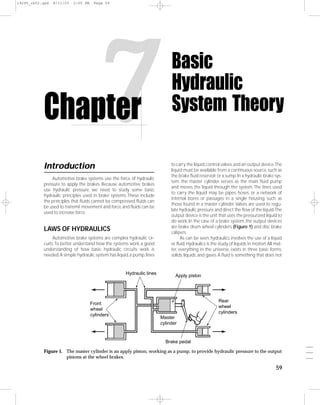
  • 1. 19295_ch02.qxd 8/11/03 2:05 PM Page 59 Chapter Introduction 7 Automotive brake systems use the force of hydraulic Basic Hydraulic System Theory to carry the liquid, control valves, and an output device.The liquid must be available from a continuous source, such as the brake fluid reservoir or a sump. In a hydraulic brake sys- tem, the master cylinder serves as the main fluid pump pressure to apply the brakes. Because automotive brakes and moves the liquid through the system. The lines used use hydraulic pressure, we need to study some basic to carry the liquid may be pipes, hoses, or a network of hydraulic principles used in brake systems. These include internal bores or passages in a single housing, such as the principles that fluids cannot be compressed, fluids can those found in a master cylinder. Valves are used to regu- be used to transmit movement and force, and fluids can be late hydraulic pressure and direct the flow of the liquid.The used to increase force. output device is the unit that uses the pressurized liquid to do work. In the case of a brake system, the output devices are brake drum wheel cylinders (Figure 1) and disc brake LAWS OF HYDRAULICS calipers. Automotive brake systems are complex hydraulic cir- As can be seen, hydraulics involves the use of a liquid cuits. To better understand how the systems work, a good or fluid. Hydraulics is the study of liquids in motion. All mat- understanding of how basic hydraulic circuits work is ter, everything in the universe, exists in three basic forms: needed. A simple hydraulic system has liquid, a pump, lines solids, liquids, and gases. A fluid is something that does not Hydraulic lines Apply piston Rear Front wheel wheel cylinders cylinders Master cylinder Brake pedal ___ Figure 1. The master cylinder is an apply piston, working as a pump, to provide hydraulic pressure to the output ___ pistons at the wheel brakes. ___ 59
  • 2. 19295_ch02.qxd 8/11/03 2:05 PM Page 60 60 • Section 2 Basic Theories and Services 100-psi pressure Weight Gas 1-square-inch input piston 100-pound 300-pound force force 3-square-inch Weight output pistons Figure 3. The mechanical force exerted on the brake pedal is transferred hydraulically to pro- vide an increased mechanical force at the Fluid wheel brake unit. Figure 2. Gases are compressible, but liquids are not. tube to the second cylinder. The pressurized fluid in the second cylinder exerts force on the bottom of the second piston, moving it upward and lifting the load on the top of have a definite shape; therefore, liquids and gases are fluids. it. By using this device, Pascal found he could increase the A characteristic of all fluids is that they will conform to the force available to do work, just as could be done with shape of their container. A major difference between a gas levers or gears. and a liquid is that a gas will always fill a sealed container, Pascal determined that force applied to liquid creates whereas a liquid may not. A gas will also readily expand or pressure or the transmission of force through the liquid. compress according to the pressure exerted on it (Figure These experiments revealed two important aspects of a liq- 2). A liquid will typically not compress, regardless of the uid when it is confined and put under pressure. The pres- pressure on it. Therefore, liquids are considered noncom- sure applied to it is transmitted equally in all directions and pressible fluids. Liquids will, however, predictably respond this pressure acts with equal force at every point in the con- to pressures exerted on them. Their reaction to pressure is tainer. the basis of all hydraulic applications. This fact allows hydraulics to do work. Pascal’s Law Pascal’s work is known as Pascal’s Law. Pascal’s Law says that pressure More than 300 years ago a French scientist, Blaise at any one point in a confined liquid is Pascal, determined that if you had a liquid-filled container with only one opening and applied force to the liquid the same in every direction and through that opening, the force would be evenly distrib- applies equal force on equal areas. uted throughout the liquid. This explains how pressur- One of the most important results of Pascal’s work ized liquid is used to operate and control the brakes on a was the discovery that fluids may be used to increase vehicle. The action of the brake pedal on the pistons force. Pascal was the person who first demonstrated inside the master cylinder pressurizes the brake fluid and the relationships of pressure, force, and motion and the fluid is delivered to the various wheel brake units (Figure 3). the inverse relationship of motion and force. In an Pascal constructed the first known hydraulic device, automobile, Pascal’s Laws are not applied just to the which consisted of two sealed containers connected by a brake system. These same hydraulic principles are at tube.The pistons inside the cylinders seal against the walls work in the hydraulic system of an automatic trans- of each cylinder and prevent the liquid from leaking out of mission. Pascal’s Laws are even at work in the move- the cylinder and prevent air from entering into the cylin- __ ment of liquid fuel from a tank to the fuel injection der. When the piston in the first cylinder has a force __ applied to it, the pressure moves everywhere within the system on the engine. __ system. The force is transmitted through the connecting
  • 3. 19295_ch02.qxd 8/11/03 2:05 PM Page 61 Chapter 7 Basic Hydraulic System Theory • 61 Fluid Characteristics force. Because energy cannot be created or destroyed, these systems only redirect energy to perform work and do not If a liquid is confined and a force applied, pressure is create more energy. Work is the amount of force applied produced. In order to pressurize a liquid, the liquid must be and the distance over which it is applied. Force is power in a sealed container. Any leak in the container will decrease working against resistance; it is the amount of push or pull the pressure. exerted on an object needed to cause motion. We usually The basic principles of hydraulics are based on certain measure force in the same units that we use to measure characteristics of liquids. Liquids have no shape of their weight: pounds or kilograms. Pressure is the amount of own; they acquire the shape of the container they are put force exerted onto a given surface area. Therefore, pressure in. They also always seek a common level. Therefore, oil in a equals the applied force (measured in pounds or kilo- hydraulic system will flow in any direction and through any grams) divided by the surface area (measured in square passage, regardless of size or shape. Liquids are basically inches or square centimeters) that is receiving the force. In incompressible, which gives them the ability to transmit customary English units, pressure is measured in pounds force. The pressure applied to a liquid in a sealed container per square inch (psi). In the metric system it can be mea- is transmitted equally in all directions and to all areas of the sured in kilograms per square centimeter, but the preferred system and acts with equal force on all areas. As a result, liq- metric pressure measurement unit is the pascal. uids can provide great increases in the force available to do The pressure of a liquid in a closed system such as a work. A liquid under pressure may also change from a liquid brake hydraulic system is the force exerted against the inner to a gas in response to temperature changes. surface of its container, which is the surface of all the lines, hoses, valves, and pistons in the system.Pressure applied to a Fluids Can Transmit Movement liquid exerts force equally in all directions. If the hydraulic Liquids can be used to transmit movement. Two cylin- pump provides 100 psi, there will be 100 pounds of force on ders of the same diameter are filled with a liquid and con- every square inch of the system (Figure 5).When pressure is nected by a pipe as shown in Figure 4. If you force piston A applied to a movable output piston, it creates output force. downward, the liquid will push piston B upward. Because If the system included a piston with an area of 30 piston A starts the movement, it is called the apply piston. square inches, each square inch would receive 100 pounds Piston B is called the output piston. If the apply piston of force. This means there would be 3,000 pounds of force moves 10 inches, the output piston also will move 10 applied to that piston (Figure 6).The use of the larger piston inches. This principle works not only for one output piston, would give the system a mechanical advantage or increase but for any number of output pistons. The principle that motion can be transmitted by a liq- uid is used in hydraulic brake systems. A master cylinder piston is pushed when the driver applies the brakes. The Reservoir master cylinder piston is the apply piston.The brake fluid in the master cylinder is connected by pipes to pistons in each of the car’s front and rear wheel brake units. Each of the wheel brake pistons is an output piston. They move whenever the master cylinder input piston moves. 100 psi Mechanical Advantage with Hydraulics Hydraulics is used to do work in the same way as a lever or gear does work. All of these systems transmit energy or Hydraulic 100 pump psi Piston A Piston B (Apply piston) (Output piston) Pipe 100 Fluid psi ___ Figure 4. Fluid can transmit motion through a closed Figure 5. While contained, the pressure of a liquid ___ system. is the same throughout the container. ___
  • 4. 19295_ch02.qxd 8/11/03 2:05 PM Page 62 62 • Section 2 Basic Theories and Services 200 Pounds 500 Pounds Reservoir Piston A Piston B 20 Input 50 Pipe Output square square inches inches 100 Figure 7. A hydraulic system also can increase force. psi Let us apply the 10 psi of pressure in the first example to an output piston with an area of 50 square inches. In this case, output force equals pressure times the surface area: P×A=F Hydraulic 100 pump Therefore, 10 psi of pressure on a 50-square-inch piston psi develops 500 pounds of output force: 10 × 50 = 500 Brake systems use hydraulics to increase force for Piston brake application. 30 square Figure 8 shows a hydraulic system with an input inches piston of 10 square inches. A force of 500 pounds is pushing 100 on the piston.The pressure throughout the system is 50 psi: 3000 lb. psi 500 (F) ÷ 10 (A) = 50 (P). of force A pressure gauge in the system shows the 50-psi pressure. 100 There are two output pistons in the system. One has psi 100 square inches of area.The 50-psi pressure in the system is transmitted equally everywhere in the system.This means that the large output piston has 50 psi applied to 100 square inches to deliver an output force of 5000 pounds: 100-square-inches × 50 psi = 5000 pounds Figure 6. One hundred psi on a 30-square-inch pis- ton generates 3000 pounds of force. The other output piston in Figure 8 is smaller than the input piston with a 5-square-inch area. The 5-square-inch area of this piston has 50-psi pressure acting on it to develop an in the force available to do work.The multiplication of force output force of 250 pounds: through a hydraulic system is directly proportional to the 5 square inches × 50 psi = 250 pounds difference in the piston sizes throughout the system. By In a brake system, a small master cylinder piston is changing the sizes of the pistons in a hydraulic system, used to apply pressure to larger pistons at the wheel brake force is multiplied, and as a result, low amounts of force are units to increase braking force. Importantly, the pistons in needed to move heavy objects. The mechanical advantage the front brakes have a larger surface area than the pistons of a hydraulic system can be further increased by the use of in the rear brakes. This creates greater braking force at the levers to increase the force applied to a piston. In Figure 7, input piston A is smaller than output pis- ton B. Piston A has an area of 20 square inches; in the exam- Pressure 50 psi ple, we are applying 200 pounds of force.Therefore, gauge 100 square inches 200 pounds (F) = 10 psi (P) Output = 5000 pounds 20 square inches (A) Input where F is force, A is area, and P is pressure. 500 pounds Output = 250 pounds If that same 200 pounds of force is applied to a piston Sectional area = of 10 square inches, system pressure is 20 psi because 5 square inches 10 square inches 200 pounds (F) __ = 20 psi (P) 10 square inches (A) Figure 8. Different-sized output pistons produce __ Therefore, pressure is inversely related to piston area. The different amounts of output force from the __ smaller the piston,the greater the pressure that is developed. same hydraulic pressure.
  • 5. 19295_ch02.qxd 8/11/03 2:05 PM Page 63 Chapter 7 Basic Hydraulic System Theory • 63 front wheels to overcome the weight transfer created by force applied to the master cylinder’s pistons and the momentum during braking. resulting brake force and piston movement at the wheels. Wheel cylinder pistons move only a fraction of an inch to Hydraulic Pressure, Force, and Motion apply hundreds of pounds of force to the brake shoes, but the wheel cylinder piston travel is quite a bit less than the Although the force available to do work is increased by movement of the master cylinder piston. Disc brake caliper using a larger piston in one cylinder, the total movement of pistons move only a few thousandths of an inch but apply the larger piston is less than that of the smaller one. When great force to the brake rotors. output force increases, output motion decreases. If the 10- This demonstrates how the use of hydraulics provides a square-inch input piston moves 2 inches as it applies 50 mechanical advantage similar to that provided by the use of psi to the 100-square-inch output piston, that output pis- levers or gears. Although hydraulic systems, gears, and levers ton will move only 0.2 inch as it applies 5000 pounds of can accomplish the same results, hydraulics is preferred output force (Figure 9).The ratio of input motion to output when the size and shape of the system are of concern. In motion is the ratio of the input piston area to the output hydraulics, the force applied to one piston will transmit piston area, and you can use this simple equation to calcu- through the fluid, and the opposite piston will have the same late it: The result from dividing the area of the input piston force on it. The distance between the two pistons in a (A1) by the area of the output piston is multiplied by the hydraulic system does not affect the force in a static system. stroke of the input piston or Therefore, the force applied to one piston can be transmitted (A1 ÷ A2) × S (the input stroke) = M (the output stroke) without change to another piston located somewhere else. or A hydraulic system responds to the pressure or force 10 square inches (input piston) = applied to it. The mere presence of different-sized pistons 100 square inches (output piston) does not always result in fluid power. The force or pressure 1 × 2 inches (input stroke) = applied to the pistons must be different in order to cause 10 fluid power. If an equal amount of pressure is exerted onto 0.2 inch output motion both pistons in a system and both pistons are the same If the output piston is larger than the input piston, it size, neither piston will move; the system is balanced or is at exerts more force but travels a shorter distance. The oppo- equilibrium. The pressure inside the hydraulic system is site also is true. If the output piston is smaller than the input called static pressure because there is no fluid motion. piston, it exerts less force but travels a longer distance. Apply When an unequal amount of pressure is exerted on the equation to the 5-square-inch output piston in Figure 9: the pistons, the piston receiving the least amount of pres- sure will move in response to the difference between the 10 square inches (input piston) = 5 square inches (output piston) two pressures. Likewise, the fluid will move if the size of the two pistons is different and an equal amount of pressure is 2 2 inches (input stroke) = × exerted on the pistons.The pressure of the fluid while it is in 1 4.0 inches output motion motion is called dynamic pressure. In this case, the smaller output piston applies only half the force of the input piston, but its stroke (motion) is twice HYDRAULIC BRAKE SYSTEMS as long. Engineers must consider these principles of force, These relationships of force, pressure, and motion in a pressure, and motion when designing a brake system for brake system are easily observed when you consider the any vehicle. If an engineer chooses a master cylinder with relatively small piston areas, the brake system can develop Pressure 50 psi very high hydraulic pressure, but the pedal travel will be gauge 0.2-inch extremely long. Moreover, if the master cylinder piston output travel travel is not long enough, this high-pressure system will not move enough fluid to apply the large-area caliper pistons 2 inches 5000 regardless of pressure. If, on the other hand, the engineer input travel pounds force selects a large-area master cylinder piston, it can move a 500 pounds 100 square large volume of fluid but may not develop enough pres- input force inches sure to exert adequate braking force at the wheels. 250 pounds force The overall size relationships of master cylinder pis- 10 square inches 4 inches 5 square tons, caliper pistons, and wheel cylinder pistons are bal- output travel inches anced to achieve maximum braking force without grabbing or fading. Most brake systems with front discs and rear ___ Figure 9. As output force increases, output travel drums have large-diameter master cylinders (a large piston ___ (motion) decreases. area) and a power booster to increase the input force. ___
  • 6. 19295_ch02.qxd 8/11/03 2:05 PM Page 64 64 • Section 2 Basic Theories and Services HYDRAULIC BRAKE FLUID the best rules are to use the fluid type recommended by the manufacturer and never mix fluid types in a system. The liquid used in a hydraulic brake system is brake fluid. The specifications for all automotive brake fluids are defined by Society of Automotive Engineers (SAE) Standard J1703 Some older European cars used a and Federal Motor Vehicle Safety Standard (FMVSS) 116. Flu- petroleum-based brake fluid.This fluid ids classified according to FMVSS 116 are assigned United States Department of Transportation (DOT) numbers:DOT 3, was colored green. Many technicians 4, and 5. Basically, the higher the DOT number (Figure 10), got into trouble by putting the wrong the more rigorous the specifications for the fluid.These spec- type of fluid in these cars or using this ifications list the qualities that brake fluid must have, such as: type of brake fluid in another system. The result was q Free flow at low and high temperatures. usually rapid and complete brake system failure. q A high boiling point (over 400°F or 204°C). q A low freezing point. q Ability to not deteriorate metal or rubber brake parts. q Ability to lubricate metal and rubber parts. Brake Fluid Boiling Point q Ability to absorb moisture that enters the hydraulic The most apparent differences among the three fluid system. grades are the minimum boiling points as listed below: Choosing the right fluid for a specific vehicle is not based DOT 3 DOT 4 DOT 5 on the simple idea that if DOT 3 is good, DOT 4 must be bet- Dry boiling point 401°F 446°F 500°F ter, and DOT 5 better still. The domestic carmakers all specify (205°C) (230°C) (260°C) DOT 3 fluid for their vehicles, but Ford calls for a heavy-duty Wet boiling point 284°F 311°F 356°F variation that meets the basic specifications for DOT 3 but has (140°C) (155°C) (180°C) the higher boiling point of DOT 4. Import manufacturers are The boiling point is important because heat generated about equally divided between DOT 3 and DOT 4. by braking can be transmitted into the hydraulic system. If DOT 3 and DOT 4 fluids are polyalkylene-glycol-ether the temperature rises too high, the fluid can boil and form a mixtures, called polyglycol. The color of both DOT 3 and vapor in the brake lines. The stopping power of the system DOT 4 fluid ranges from clear to light amber. DOT 5 fluids are then will be reduced. As a result, the brake pedal can go to all silicone based because only silicone fluid—so far—can the floor and the vehicle will not stop. meet the DOT 5 specifications. No vehicle manufacturer, The dry boiling point is the minimum boiling point of however, recommends DOT 5 fluid for use in its brake sys- new, uncontaminated fluid. Because brake fluids are hygro- tems. Although all three fluid grades are compatible they do scopic, their boiling points decrease due to water contami- not combine well if mixed together in a system. Therefore, nation after the fluid has been in service for some time. Brake systems are not completely sealed, and some expo- sure of the fluid to air is inevitable. Other Brake Fluid Requirements A high-temperature boiling point is not the only requirement brake fluid must meet. Brake fluid must remain stable throughout a broad range of temperatures, and it must retain a high boiling point after repeated exposure to high temperatures. Brake fluid must also resist freezing and evaporation and must pass specific viscosity tests at low temperatures. If the fluid thickens and flows poorly when cold, brake operation will suffer. Besides temperature requirements, brake fluid must pass corrosion tests. It also must not contribute to deterio- ration of rubber parts and must pass oxidation-resistance tests. Finally, brake fluid must lubricate cylinder pistons and bores and other moving parts of the hydraulic system. DOT 5 Silicone Fluid __ Figure 10. The DOT number is always clearly stated Silicone DOT 5 fluid does not absorb water. This purple __ on a container of brake fluid. fluid has a very high boiling point, is noncorrosive to __
  • 7. 19295_ch02.qxd 8/11/03 2:05 PM Page 65 Chapter 7 Basic Hydraulic System Theory • 65 hydraulic system components, and does not damage paint brake system, the reservoir is attached to the top of the mas- like ordinary fluid does. DOT 5 fluid also has some other ter cylinder, although some vehicles might use tubing to characteristics that are not so beneficial. connect the reservoir to the master cylinder. Brake fluid is Silicone fluid compresses slightly under pressure, forced out of the pan by atmospheric pressure into the mas- which can cause a slightly spongy brake pedal feel. Silicone ter cylinder and returned to it after the brake pedal has been fluid also attracts and retains air more than polyglycol fluid let up. does, which makes brake bleeding harder; it tends to out- gas slightly just below its boiling point, and it tends to aer- ate from prolonged vibration. DOT 5 fluid has other Venting problems with seal wear and water accumulation and sepa- In order to allow the fluid to flow into the master cylin- ration in the system. All of these factors mean that DOT 5 sil- der, the reservoir has an air vent that allows atmospheric icone fluid should never be used in an ABS. pressure to force the fluid into the master cylinder when a low pressure is created by the movement of the pistons.The Hydraulic System Mineral Oil (HSMO) vent is positioned above the normal brake fluid level in the Fluids reservoir and keeps atmospheric pressure at the top of the fluid. HSMO is the least common type of brake fluid, being used by only three carmakers: Citroen, Rolls Royce, and in some Audi models in their brake booster system.HSMO is not a polyglycol or silicone fluid,but rather is made from a mineral VACUUM AND AIR PRESSURE oil base.It has a very high boiling point, it is not hygroscopic, it PRINCIPLES is a very good lubricant, and it actively prevents rust and cor- A law of nature defines the role of atmospheric pres- rosion. HSMO fluid can be identified by its green color. sure on the operation of a brake system. The law simply Because HSMO is petroleum based, systems designed states that whenever a high pressure is introduced to a for its use also require seals made of special rubber. If poly- lower pressure, it moves to equalize the pressures. In other glycol or silicone fluid is used in a system designed for words, something that has a high pressure will always HSMO, these fluids will destroy the HSMO system seals. move toward something that has a lower pressure. The force at which the higher pressure moves toward the lower pressure is determined by the difference in pressures.When You If HSMO is used in a system designed for the pressure is slightly lower than atmospheric, the force is Should polyglycol or silicone fluid, it will destroy low. When there is a large difference, the higher pressure Know will rush into the lower and the force will be great. the seals of those systems. HSMO is not In the world of automotive technology, any pressure covered by the DOT classifications of FMVSS 116 and that is lower than atmospheric pressure is called a vacuum. is not compatible with DOT fluids. Atmospheric pressure (Figure 11) is the pressure of the air Fluid Compatibility 1" { Although the performance requirements of DOT 3, 4, and 5 fluids are different, FMVSS 116 requires that DOT 3 and 4 fluids must be compatible with each other in a sys- 1" tem. Mixing DOT 3 and DOT 4 in a system is not recom- Approx. mended, but it can be done without damaging the system 20 miles or creating a damaging reaction. DOT 5 should never be Lb s .7 mixed with DOT 3 or 4 fluids. 14 If DOT 3 and DOT 4 fluids are mixed in a system, the boiling point of the DOT 4 fluid will be reduced by the same percentage as the percentage of DOT 3 fluid in the mixture. Thus, overall system performance can be compromised by mixing fluids. Figure 11. A square-inch column of air the height of Reservoir the earth’s atmosphere exerts 14.7 pounds All hydraulic systems require a reservoir to store fluid of pressure on the Earth’s surface at sea ___ and to provide a constant source of fluid for the system. In a level. ___ ___
  • 8. 19295_ch02.qxd 8/11/03 2:05 PM Page 66 66 • Section 2 Basic Theories and Services around and on us and has a value of approximately 14.7 psi assist for the driver (Figure 12). The rush of high pressure at sea level. When we are at higher elevations, there is less toward an area of vacuum causes an increase in force, air above and on us and therefore the pressure of the at- much like a lever. mosphere is less, but that air is still considered atmo- spheric pressure, and any pressure less than that is a vacuum. Atmospheric 15 psi When the pistons inside a master cylinder move, the pressure volume of the piston’s cylinder changes. When the volume decreases, the pressure increases. When the piston moves Piston Vacuum back to its original location, the pressure is lower and atmo- pump spheric pressure pushes fluid from the reservoir into the Vacuum cylinder. The relationship of vacuum and atmospheric pressure Figure 12. Vacuum (low pressure) works with at- is used in most power brake systems to provide a power mospheric pressure to develop force. Summary s In a hydraulic brake system, the master cylinder moves s Most brake systems with front discs and rear drums brake fluid through the system.The lines used to carry the have large-diameter master cylinders (large piston area) liquid may be pipes,hoses,or a network of internal bores and a power booster to increase the input force. or passages in a single housing, such as those found in s DOT 3 and DOT 4 fluids are polyglycol mixtures. The a master cylinder. Valves are used to regulate hydraulic color of both DOT 3 and DOT 4 fluids ranges from clear pressure and direct the flow of the liquid. The output to light amber. devices are brake drum cylinders and disc brake calipers. s DOT 5 fluids are all silicone based, and no vehicle man- s Hydraulics is the study of liquids in motion. ufacturer recommends DOT 5 fluid for use in its brake s Liquids are considered noncompressible fluids. systems. s Pascal’s Law says that pressure at any one point in a s Although the performance requirements of DOT 3 and confined liquid is the same in every direction and 4 fluids are different, FMVSS 116 requires that the applies equal force on equal areas. grades of fluid be compatible with each other in a sys- s If a liquid is confined and a force applied, pressure is tem; however, mixing different types of fluid in a sys- produced. If the pressure on the fluid is applied to a tem is not recommended. movable output piston, it creates output force. s All hydraulic systems require a reservoir to store fluid s In a brake system, a small master cylinder piston is and to provide a constant source of fluid for the system. used to apply pressure to larger pistons at the wheel s The relationship of vacuum and atmospheric pressure brake units to increase braking force. is used in most power brake systems. Review Questions 1. Explain how hydraulic fluid can be used to transmit cian B says that the output piston will move one-third motion. as far as the input piston. Who is correct? 2. Hydraulic systems work because fluids cannot be A. Technician A only ____________. B. Technician B only 3. The pressure in a hydraulic system is the same in C. Both Technician A and Technician B ________ directions. D. Neither Technician A nor Technician B 4. A hydraulic system with a 1-square-inch input piston 5. Technician A says that DOT 3 brake fluid has a higher and a 3-square-inch output piston is being discussed. boiling point than DOT 5. Technician B says that DOT 4 Technician A says that the output piston will have brake fluid has a lower boiling point than DOT 5. Who three times as much force as the input piston. Techni- is correct? A. Technician A only B. Technician B only __ C. Both Technician A and Technician B __ D. Neither Technician A nor Technician B __