
Recomendados
Mais conteúdo relacionado
Mais procurados
Mais procurados (20)
Semelhante a Tool maker microscope
Semelhante a Tool maker microscope (20)
Último
Último (20)
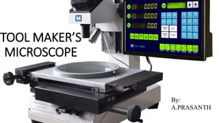
Tool maker microscope
- 2. CONTENT • INTRODUCTION • PRINCIPLE OF MEASUREMENT • CONSTRUCTION OR ELEMENTS • WORKING • EXAMPLE • APPLICATION
- 3. INTRODUCTION The tool maker’s microscope is a versatile measuring instrument which is use to measure small and delicate parts by optical means without the application of pressure. It is designed for: Measurement of complex form e.g. - profile of external thread, tool, templates, gauges, etc. Measuring Centre to Centre distance of holes in any plane. A variety of linear measurements. Accurate angular measurements. It can measure upto 1 micrometre and 1 minute.
- 4. PRINCIPLE OF MEASUREMENT • A ray of light from a light source is reflected by a mirror through 90˚. • It then passes through a transparent glass plate. • A shadow image of the outline or counter of the workspaces passes through the objective of the optical head & is projected by a system of three prisms to a ground glass screen. • Observations are made through an eyepiece. • Measurements are made by means of cross lines engraved on the ground glass screen. • The screen can be rotated through 360˚ the angle of rotation is read through an auxiliary eyepiece.
- 6. Main Components of Tool Maker’s Microscope 1. Rotatable Table, 2. Measuring Stage, 3. Moveable Head, 4. Ocular (Eye piece), 5. Projection Screen, 6. Micrometres, 7. Objective Lens, 8. Prism.
- 8. CONSTRUCTION OF THE TOOLMAKER’S MICROSCOPE • The microscope consists of a rigid stand on which a moveable head is mounted. • The measuring stage moves on ball guide ways by actuating two measuring micrometers arranged perpendicular to each other in the length and the cross- sections. • The measuring range of each micrometer is 25 mm and the measuring capacity can be increased using slip gauges. • A rotatable table is provided over the stage, on which the work-piece can be fixed either directly or between centres. • This table can be rotated though 360 ͦ and the angular rotation can be read by fixed Vernier.
- 9. WORKING • The component being measured is illuminated by the through light method. • A parallel beam of light illuminates the lower side of work-piece which is then received by the objective lens in its way to a prism that deflects the light rays in the direction of the measuring ocular & the projection screen. • The direction of illumination can be tilted with respect to the work-piece by tilting the measuring head & the whole optical system.
- 10. EXAMPLES Pitch Measurement: - • Take the hacksaw blade and mount on the moving blade of tool maker’s Microscope in horizontal position. • Focus the microscope on the blade. • Make the cross line in the microscope coincided with one of the edge of the blade. • Take a reading on ground glass screen, this is the initial reading. • The table is again moved until the next edge of the blade coincides with the cross-line on the screen and the final reading takes. • the difference between initial and final reading gives pitch of the blade.
- 11. Teeth Angle: - • Place the blade on the table in same position. • Rotate the screen until a line on the angle of screen rotation is noted. • Take the angular reading, the initial one. • Again rotate the screen until the same line coincides with the other flank of the tooth. • Take the final angular reading. • The teeth angle of blade in the difference between the two angular readings.
- 12. APPLICATION o Determination of the Relative Positions: It is used for the determination of the relative position of various points on work by measuring the travel necessary to bring a second point to the position previously occupied by the first, and so on. o Measurement of Angles: Measurement of angles is possible in toolmaker’s microscopes by using a protractor eyepiece. o Comparison Measurement : A toolmaker’s microscopes also do comparisons of thread forms, measurement of pitch and effective diameter. In this case the comparison is done with master profiles engraved in the eyepiece. o Comparison with a Scale : Comparisons of enlarged projected images with a scale tracing fixed projection screen are also done in a toolmaker’s microscope.
- 13. KEY WORD’S OF TOOLMAKER’S MICROSCOPE Achromatic Condenser : A combination of lenses made of different glass, used to produce images free of chromatic aberrations is called achromatic condenser. Projection Lens : The lens that magnifies and transmits the object contour or image resulting from the collimated parallel light rays for projecting rays of light over a screen. They are also called condensing lens. Magnification : It is defined as the ratio of the screen diameter to the field diameter in a microscope. Field Diameter : It is defined as diameter of the area that can be projected on the screen.