Call Girls Wakad Call Me 7737669865 Budget Friendly No Advance Booking
Hydraullically assisted pressure relief valve service sheet
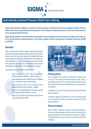
1. Sigma Energy Solutions (Sigma) can check the correct operation and adjust the lift pressure settings for boiler and other
safety relief valves using hydraulic assist equipment. Valve testing and adjustment can be carried out with the plant on
line at normal operating pressures.
Sigma Energy Solutions uses equipment and procedures that can reliably test the lift pressure of safety relief valves on-
line at normal process operating pressure. The system complies with the requirements of Australian Standards AS1228
and AS1271.
Hydraulically Assisted Pressure Relief Valve Setting
Benefits
Within a process plant where vessels or piping contain fluids
at elevated pressures, statutory requirements and the owner’s
duty of care to the workforce requires that safety relief valves
must be tested and adjusted periodically as well as after any
valve maintenance. The Sigma system can be used for testing
and adjustment of safety and safety relief valves without
interrupting plant operation or over-pressuring the system.
Advantages of using the Sigma system include:
• valves can be tested ‘in-situ’ with plant on-line at
normal operating conditions – (lower stress);
• testing discharges only a limited amount of process
fluid – (minimum noise and valve wear);
• higher pressure valves can be tested without
gagging those with lower settings – (safety);
• testing time is significantly less than that required
for increasing process pressure – (cost);
• results are recorded and provided in report format
– (documented test results).
CONDITION ASSESSMENT
Prerequisites
To be suitable for use with our equipment, a safety valve
must be of the conventional spring closure type, have a
removable cap with 400 mm overhead clearance and a length
of accessible thread above the adjusting nut for connection of
a lift adaptor.
To calculate the valve lift, the actual dimensions of the valve
seat are required.
A pressure tapping point adjacent to the valve being tested
is also required to provide an accurate measurement of the
process pressure.
Plant condition
Sigma installs a precision pressure transducer adjacent to
the valve for test purposes but results can be calculated from
process pressures if their measurement accuracy is suitable.
The test equipment requires 240V AC power and a 700 kPa
air supply.
2. ENVIRONMENTAL IMPROVEMENT
How it works
In basic terms, safety valves consist of a lapped disc held
against a valve seat by a compressed spring. At the valve
set pressure, the pressure force on this disc just equals the
spring force holding the valve closed. Conventional testing
of safety valves, (live lifting), involves progressively raising
system pressure until the valve opens. The pressure is then
recorded.
The principal of the test system is to add controlled hydraulic
force to add to the process system pressure to overcome the
closing force of the valve spring. This applied hydraulic force
is measured by an electronic load cell and recorded by a
computer logging system. This system also records the valve
spindle movement from a displacement transducer and the
system pressure from a calibrated pressure transducer which
measures system pressure near the relief valve location.
From these results and the known valve seat dimensions, the
computer evaluates the lift pressure and also estimates the
reseat pressure, (blowdown).
The production of accurate results is dependent on knowing
precisely the valve seat area and the system pressure acting
on the seat at the time of test.
Service experience with the test system shows that when
correctly calibrated and operated it will enable set pressures
to be established with +/- 1%. With experience, the recorded
graph can be interpreted to identify potential problems such
as a passing valve, a sluggish valve, a valve with a long
‘blowdown’ or a long ‘simmer’.
The computer logger records the line system pressure
together with the additional force applied by the load cell and
the valve spindle movement. A typical example clearly shows
the valve lift and reseat events from which the peak load is
measured for calculation of the lift pressure.
CONDITION ASSESSMENT
7 Terrace Place, Metroplex on Gateway, Murarrie, Queensland 4172 Australia
PO Box 268 Cannon Hill Queensland 4170 Australia
telephone: +61 (0) 7 3902 9900 fax: +61 (0) 7 3902 9999
email: sales@sigenergy.com web: www.sigenergy.com
SS2S9(10/05)
Prior to commencing site tests, the mechanical rig is
assembled with the selected load cell and a proving ring is
used to confirm the calibration of the load cell. The original
calibration of the load cell and ring gauge is traceable to
National Standards. Both the proving ring and pressure
transducer are calibrated in accordance with N.A.T.A.
requirements.