Soil Nailing
•
192 gostaram•76,888 visualizações

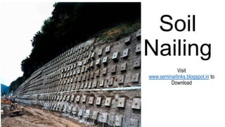
Soil nailing is a technique used to reinforce and strengthen existing ground.Soil nailing consists of installing closely spaced bars into a slope or excavation as construction proceeds from top down.It is an effective and economical method of constructing retaining wall for excavation support, support of hill cuts, bridge abutments and high ways.This process is effective in cohesive soil, broken rock, shale or fixed face conditions.

Recomendados
Mais conteúdo relacionado
Mais procurados
Mais procurados (20)
Semelhante a Soil Nailing
Semelhante a Soil Nailing (20)
Mais de Seminar Links
Mais de Seminar Links (20)
Último
Último (20)
Soil Nailing
- 2. INTRODUCTION • Soil nailing is a technique used to reinforce and strengthen existing ground. • Soil nailing consists of installing closely spaced bars into a slope or excavation as construction proceeds from top down. • It is an effective and economical method of constructing retaining wall for excavation support, support of hill cuts, bridge abutments and high ways. • This process is effective in cohesive soil, broken rock, shale or fixed face conditions.
- 3. Origins • Soil nailing evolved from the New Austrian Tunneling method which is a system for underground excavations in rock. • This concept of combining passive steel reinforcement and shotcrete has also been applied to the stabilization of rock slopes since the early 1960s. • The first application of soil nailing was implemented in 1972 for a railroad widening project near Versailles, France. • The technique included installing high-density, grouted soil nails into a 60-ft.-high wall and facing it with reinforced concrete. • The United States first used soil nailing in 1976 for the support of a 13.7 m deep foundation excavation in dense silty sands.
- 4. Applications • Stabilization of railroad and highway cut slopes • Excavation retaining structures in urban areas for high-rise building and underground facilities • Tunnel portals in steep and unstable stratified slopes • construction and retrofitting of bridge abutments with complex boundaries involving wall support under piled foundations • Stabilizing steep cuttings to maximize development space. • The stabilizing of existing over-steep embankments. • Soil Nailing through existing concrete or masonry structures such as failing retaining walls and bridge abutments to provide long term stability without demolition and rebuild costs. • Temporary support can be provided to excavations without the need for bulky and intrusive scaffold type temporary works solutions.
- 5. Nails • Driven Nails • Grouted Nails • Corrosion Protected Nails • Jet grouted Nails • Launched Nails
- 6. Driven Nails • Generally small-diameter nails (15-46 mm) with a relatively limited length (to about 20 m) made of mild steel (about 50 ksi) that are closely spaced in the wall (two to four nails per square meter). • Nails with an axial channel can be used to permit the addition of grout sealing. • Driven nails are the quickest (four to six per hour) and most economical to install (with a pneumatic or hydraulic hammer).
- 7. Grouted Nails • Steel bars, with diameters ranging from 15 to 46 mm, stronger than driven nails (about 60 ksi). • Grouted nails are inserted into boreholes of 10-15 cm and then cementgrouted. • Ribbed bars are also used to increase soil adhesion. • Corrosion-protected nails • For aggressive soils as well as for permanent structures.
- 8. Jet-grouted Nails • A composite of grouted soil and a central steel rod, up to 40 cm thick. • Nails are installed using a high-frequency vibro percussion hammer, and cement grouting is injected during installation. • This method has been shown to increase the pullout resistance of the composite, and the nails are corrosion-resistant.
- 9. Launched Nails • Nails between 25 and 38 mm in diameter and up to 6 m or longer are fired directly into the soil with a compressed-air launcher. • Used primarily for slope stabilization. • This technique involves the least site disturbance.
- 10. Typical soil nail wall arrangement
- 12. Design • After a preliminary analysis of the site, initial designs of the soil nail wall can be begin. • This begins with a selection of limit states and design approaches. • The two most common limit states used in soil nail wall design is strength limit and service limit states.
- 13. Limit States • The strength limit state is the limit state that addresses potential failure mechanisms or collapse states of the soil nail wall system. • The service limit state is the limit state that addresses loss of service function resulting from excessive wall deformation and is defined by restrictions in stress, deformation and facing crack width under regular service conditions.
- 14. Design Approaches • The two most common design approaches for soil nail walls are limit state design and service load design. • Initial design considerations include wall layout (wall height and length), soil nail vertical and horizontal spacing, soil nail pattern on wall face, soil nail inclination, soil nail length and distribution, soil nail material and relevant ground properties. • The next step is to use simplified charts to preliminarily evaluate nail length and maximum nail force. • Nail length, diameter and spacing typically control external and internal stability of the wall.
- 15. Cont.. • These parameters can be adjusted during design until all external and internal stability requirements are met. • After the initial design is completed, final design progresses where the soil nail wall has to be tested for external and internal failure modes, seismic considerations and aesthetic qualities. • Drainage, frost penetration and external loads such as wind and hydrostatic forces also have to be determined and included in the final examination of the design.
- 16. Machineries Used For Soil Nailing • Drilling Equipments • Grout Mixing Equipments • Shotcreting / Guniting Equipments • Compressor
- 17. Drilling Equipment • Rotary air-flushed and water-flushed • Down-the-hole hammer • Tri-cone bit • It is important to procure drilling equipment with sufficient power and rigid drill rods.
- 18. Grout Mixing Equipment • In order to produce uniform grout mix, high speed shear colloidal mixer should be considered. • Powerful grout pump is essential for uninterrupted delivery of grout mix. • If fine aggregate is used as filler for economy, special grout pump shall be used.
- 19. Shotcreting/Guniting Equipment • Dry mix method will require a valve at the nozzle outlet to control the amount of water injecting into the high pressurized flow of sand/cement mix. • For controlling the thickness of the shotcrete, measuring pin shall be installed at fixed vertical and horizontal intervals to guide the nozzle man.
- 20. Compressor • The compressor shall have minimum capacity to delivered shotcrete at the minimum rate of 9m3/min. • Sometimes, the noise of compressor can be an issue if the work is at close proximity to residential area, hospital and school.
- 21. Materials Used For Soil Nailing • Steel Reinforcements • Grout Mix • Shotcrete/Gunite
- 22. Steel Reinforcements • For corrosion protection, all steel component shall be galvanized. • If machine threading after galvanization is unavoidable, then proper zinc based coating shall be applied onto the thread. • For double corrosion protection, the PVC corrugated pipe used shall be of good quality and adequate thickness. • Preferably galvanized corrugated steel pipe shall be used.
- 23. Grout Mix • For conventional soil nail, the water cement ratio of the grout mix ranges from 0.4 to 0.5. • As most cementitious grout will experience some grout shrinkage, non-shrink additive can be used to reduce breeding and grout shrinkage. • The resistance at grout-soil interface of nail will significantly reduced when the grout shrink.
- 24. Shotcrete/Gunite Shotcrete or gunite can be continuous flow of mortal or concrete mixes projected at high speed perpendicularly onto the exposed ground surface by means of pneumatic air blowing for dry mix or spraying for wet mix.
- 25. Typical soil nail head plate and shotcrete details
- 26. Initial Excavation • This initial excavation will be carried out by trimming the original ground profile to the working platform level where the first row of soil nails can be practically installed. • The pre-requisite of this temporary excavation shall be in such a way that the trimmed surface must be able to self support till completion of nail installation. • Sometimes, sectional excavation can be carried out for soil with short self support time. • If shotcrete/gunite is designed as facing element, the condition of the trimmed surface shall be of the satisfactory quality to receive the shotcrete.
- 27. Drilling of Holes • Drilling can be done by either air- flushed percussion drilling, auguring or rotary wash boring drilling depending on ground condition. • The size of drilled hole shall be as per the designed dimension. Typically, the hole size can range from 100mm to 150mm. • In order to contain the grout, the typical inclination of the drill hole is normally tilted at 15º downward from horizontal. • Flushing with air or water before nail insertion is necessary in order to remove any possible collapsed materials, which can potentially reduce the grout- ground interface resistance.
- 28. Insertion of Nail Reinforcement And Grouting • The nail shall be prepared with adequate centralizers at appropriate spacing and for proper grout cover for first defense of corrosion protection. • In additional to this, galvanization and pre- grouted nail encapsulated with corrugated pipe can be considered for durability. • A grouting pipe is normally attached with the nail reinforcement during inserting the nail into the drilled hole. • The grouting is from bottom up until fresh grout return is observed from the hole. • The normal range of water/cement ratio of the typical grout mix is from 0.45 to 0.5.
- 29. Advantages • With the right soil and site conditions, a rapid and economical means of constructing earth retention support systems and retaining walls. • Creates less noise and traffic obstructions. • Less impact on nearby properties • Allow in-situ strengthening on existing slope surface with minimum excavation and backfilling, particularly very suitable for uphill widening, thus environmental friendly. • Allow excellent working space in front of the excavation face, • Can be used for strengthening of either natural slope, natural or manmade cut slopes, • Grouting only once is required, saving time and labor. • The technique is flexible, easily modified.
- 30. Disadvantages • Nail encroachment to retained ground rendering unusable underground space, • Generally larger lateral soil strain during removal of lateral support and ground surface cracking may appear, • Tendency of high ground loss due to drilling technique, particularly at course grained soil, • Less suitable for course grained soil and soft clayey soil, which have short self support time, and soils prone to creeping, • Suitable only for excavation above groundwater
- 31. Conclusion Soil nailing is an accepted technology, the theoretical aspects of which are well understood and well reported in technical literature. However, research indicates that there are few practical guidelines available that offer a comprehensive, experience-based insight into the construction considerations that should be addressed before a soil nail system design is finalized and implemented.
- 32. References • http://www.deepexcavation.com/en/soil-nail-wall • http://www.moretrench.com/b_literature_article.php • http://en.wikipedia.org/wiki/Soil_nailing