MAE 564 (1)
•
0 gostou•137 visualizações

This document describes the design of a vibratory bowl feeder (VBF) to feed bottles and caps into an assembly system for the biomedical industry. The design process included determining the optimal dimensions of the bottle (diameter of 36mm and height of 56mm to hold 60ml) and cap. The stable orientation for the cap is horizontal bottom side open, while for the bottle it is vertical opening facing top. The VBF design uses passive systems like wiper blades and slots as well as active systems like air pressure to guide the parts into the stable orientations for assembly. CAD models and diagrams illustrate the final VBF pathway designs for the bottle and cap.

Recomendados
Mais conteúdo relacionado
Semelhante a MAE 564 (1)
MAE 564 (1)
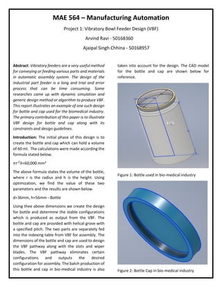
- 1. MAE 564 – Manufacturing Automation Project 1: Vibratory Bowl Feeder Design (VBF) Arvind Ravi - 50168360 Ajaipal Singh Chhina - 50168957 Abstract: Vibratory feeders are a very useful method for conveying or feeding various parts and materials in automatic assembly system. The design of the industrial part feeder is a long and trial and error process that can be time consuming. Some researches came up with dynamic simulation and generic design method or algorithm to produce VBF. This report illustrates an example of one such design for bottle and cap used for the biomedical industry. The primary contribution of this paper is to illustrate VBF design for bottle and cap along with its constraints and design guidelines. Introduction: The initial phase of this design is to create the bottle and cap which can hold a volume of 60 ml. The calculations were made according the formula stated below. 𝜋𝑟2 ℎ=60,000 mm3 The above formula states the volume of the bottle, where r is the radius and h is the height. Using optimization, we find the value of these two parameters and the results are shown below. d=36mm, h=56mm - Bottle Using thee above dimensions we create the design for bottle and determine the stable configurations which is produced as output from the VBF. The bottle and cap are provided with helical grove with a specified pitch. The two parts are separately fed into the indexing table from VBF for assembly. The dimensions of the bottle and cap are used to design the VBF pathway along with the slots and wiper blades. The VBF pathway eliminates certain configurations and outputs the desired configuration for assembly. The batch production of this bottle and cap in bio-medical industry is also taken into account for the design. The CAD model for the bottle and cap are shown below for reference. Figure 1: Bottle used in bio-medical industry Figure 2: Bottle Cap in bio-medical industry
- 2. Possible Orientation: Bottle: Cap: Vibratory bowl feeder Design: In this report we will be explaining the vibratory design for two parts, cap and bottle respectively. CAP stable configuration: Horizontal bottom Side Open. VBF for CAP: For designing the pathway or trajectory we came up with a set of design guidelines as penned below Positive thread of 6o angle was created for the cap – VBF design The width of the trajectory path was considered to be 36mm. In-order to eliminate two of the horizontal standing orientation we created a wiper blade of 45o angle. – Passive system This wiper blade will eliminate two vertical orientations for the cap. Then we brought-in scallop to eliminate the horizontal bottom side open position. - Passive system Then we had a ridge to invert from horizontal top side open position to the bottom side open position. – Active System The stable configuration is the given as the output The VBF pathway for the cap is shown in the figure. Figure 3: VBF design pathway for the cap Bottle Stable configuration: Vertical opening facing top is the stable configuration VBF for Bottle: Design guidelines for VBF design are followed and penned below Positive thread of 6o angle was created for the cap – VBF design The width of the trajectory path was considered to be 36 mm. The wiper blades are placed initially to eliminate the vertical orientation. The angle of the wiper blade is 45o. -Passive system This wiper blade will eliminate two vertical orientations for the bottle. Narrow track is provided in-order to eliminate other orientation other than horizontal one. - Passive system Air pressure is provided in-order to act as a torque controller where it changes the orientation of the horizontal bottle
- 3. depending upon the center of gravity. – Active system Slot or gap is provided to eliminate the position where the open side is in the direction of the conveyor because the center of gravity is above the center line of the cylinder i.e. more oriented towards the top side. The output orientation is fed inside a 3-d tube in the downward direction which outputs the stable configuration. –Passive system Figure 4: VBF pathway for the bottle. References: Lecture 3 videos Geometry and part feeding Journal paper