SlideShare uma empresa Scribd logo
1 de 14
Baixar para ler offline
9932 East 58th Street | Tulsa, OK 74146-6411 USA | +1-918-622-6161 | 1-800-336-2736 U.S./Canada
15
ENARDO Flame Arrestor Technology
A Flame Arrestor is a device which allows gas to pass
through it but stops a flame in order to prevent a larger fire
or explosion. There is an enormous variety of situations
in which flame arrestors are applied. Anyone involved in
selecting flame arrestors needs to understand how these
products work and their performance limitations. For
that purpose, this paper provides an introduction to the
technology and terminology of flame arrestors and the types
of products available.
Figure 1. The earliest flame arrestors: Davy safety lamps for
coal miners.
Blocking Flame With Narrow Passages
The operating principle of flame arrestors was discovered in
1815 by Sir Humphry Davy, a famous chemist and professor
at the Royal Institution in England. A safety committee of
the English coal mining industry had approached Davy for
technical assistance. They needed a way to prevent miners’
oil lamps from causing explosions when flammable gas
called firedamp seeped into the mine shafts. Sir Humphry
studied the gas, which consisted mostly of methane. The
investigation centered on how methane burns under various
conditions and with various proportions of air. Davy’s
solution was to enclose the lamp flame securely with a tall
cylinder of finely woven wire screen called metal gauze.
Three of the earliest Davy safety lamps are shown in Figure 1.
Enough lamplight passes out through the screen to be
useful. Air for the oil flame around the lamp wick enters
through the lower part of the screen. Hot exhaust gas
escapes through the upper part. When a combustible
mixture of methane flows in with the air, a methane flame
burns against the inside of the screen. However, neither
the methane flame nor the lamp flame passes through the
narrow openings of the screen. The metal wire absorbs heat
from the flame and then radiates it away at a much lower
temperature.
Modern Flame Arrestors
Since Sir Humphry’s time, flame arrestors of numerous
varieties have been applied in many industries. All of them
operate on the same principle: removing heat from the flame
as it attempts to travel through narrow passages with walls
of metal or other heat-conductive material. For instance,
flame arrestors made by Enardo employ layers of metal
ribbons with crimped corrugations as shown in Figure 2.
Flame Cell Channel
Figure 2. Concept of flame arrestor element used in Enardo
products, featuring a crimped wound metal ribbon element
Flame arrestors are used in approximately 22 industries,
including refining, pharmaceutical, chemical, petrochemical,
pulp and paper, oil exploration and production, sewage
treatment, landfills, mining, power generation, and bulk
liquids transportation. In some cases, the flames involve
exothermic (heat-producing) reactions other than oxidation.
Processes which generate the combustible or reactive
gases include blending, reacting, separation, mixing,
drilling, and digesting. These processes involve numerous
equipment configurations and gas mixtures.
Flame Arrestor Technology
Revision A
ENARDO | www.enardo.com
16
ENARDO Flame Arrestor Technology
(Speaking non-technically, deflagration means rapid burning,
and detonation means explosion.) These units are installed
in pipes to prevent flames from passing, as shown in Figure 5.
Figure 5. A typical Enardo in-line flame arrestor.
Most in-line flame arrestor applications are in systems which
collect gases emitted by liquids and solids. These systems,
commonly used in many industries, may be called vapor
control systems. The gases which are vented to atmosphere
or controlled via vapor control systems are typically
flammable. If the conditions are such that ignition occurs, a
flame inside or outside of the system could result, with the
potential to do catastrophic damage.
One variety of vapor control systems is called vapor
destruction systems. Included are elevated flare systems
(Figure 6), enclosed flare systems, burner and catalytic
incineration systems, and waste gas boilers.
Figure 6. An in-line flame arrestor in a flare system.
Another type of vapor control system using in-line flame
arrestors is vapor recovery systems. Included here are
vapor balancing, refrigeration, adsorption, absorption, and
compression systems.
End-Of-Line, Vent-To-Atmosphere Type
Most flame arrestor applications and designs fall into two
major categories. One group consists of end-of-line flame
arrestors, also known as the vent-to-atmosphere type
(Figure 3).
Figure 3. End-of-line flame arrestors are used in applications
such as petroleum storage tank vents.
The classic application is in preventing fire in the
atmosphere from entering an enclosure. Around 1920, for
instance, flame arrestors began to be installed on vents on
oilfield storage tanks. They keep the tanks from exploding
when gas flowing from the vents is struck by lightning
(Figure 4).
Figure 4. Oilfield storage tank vents were an early
application of industrial flame arrestors.
Conversely, some end-of-line flame arrestors prevent fire in
an enclosure from igniting an explosive atmosphere such as
in a refinery. For instance, flame arrestors may be installed in
furnace air inlets and exhaust stacks. The Davy lamp might
be considered another example of that sort.
In-Line, Deflagration Or Detonation Type
The other major category consists of in-line flame arrestors,
also known as deflagration and detonation flame arrestors.
Revision A
9932 East 58th Street | Tulsa, OK 74146-6411 USA | +1-918-622-6161 | 1-800-336-2736 U.S./Canada
17
ENARDO Flame Arrestor Technology
Figure 7. An in-line flame arrestor used in an end-of-line
application (below a pressure and vacuum relief valve for a
liquid storage tank).
For example, the primary flame safety devices in a vapor
control system are usually active ones such as liquid
seals and oxygen analyzers as shown before in Figure 6.
However, active devices can be rendered ineffective by
loss of power, failure of mechanical components, failure of
electronic communication, or human error. Flame arrestors,
in turn, are the system’s secondary or fail-safe provision. In
other words, if the active, primary method malfunctions, the
passive, secondary method will be the last defense against
an explosion.
Flame Propagation
The differences between the various types of flame arrestors
are based mainly on the nature of the flame which is
expected (especially how fast it moves) and on the expected
intensity of the pressure pulse created by the flame. A flame
is a volume of gas in which a self-sustaining exothermic
(heat-producing) chemical reaction is occurring. The reaction
is presumed to be oxidation, also known as combustion.
To have a flame, three things must be present; oxygen
(supplied by air), very high temperature (initially supplied by
an ignition source) and a flammable gas mixed with the air in
However, in-line flame arrestors are sometimes used in
end-of-line applications. For instance, an in-line unit may be
mounted below a tank vent valve on a liquid storage tank
(Figure 7). The valve reduces emissions and product loss,
while the flame arrestor protects the tank from flames in the
atmosphere during venting of flammable gases.
As technology throughout the world has become more
complicated, safety products have also evolved to meet
new requirements. Flame arrestors, in particular, changed
immensely during the last decade of the twentieth century.
As will be explained later, flames in pipes can reach much
higher speeds and pressures than in the open atmosphere.
Therefore in-line flame arrestors are now subdivided
into three categories on that basis. Furthermore, special
provisions are made for each of the three major groups of
gases according to degree of flame hazard (also explained
later)—NEC Groups B, C, and D. Thus, there are now as
many as twelve different types of flame arrestors, as follows:
	 1.	 End-of-line, Group B
	 2.	 End-of-line, Group C
	 3.	 End-of-line, Group D
	 4.	 In-line, low/medium-press. deflagration, Group B
	 5.	 In-line, low/medium-press. deflagration, Group C
	 6.	 In-line, low/medium-press. deflagration, Group D
	 7.	 In-line, high-pressure deflagration, Group B
	 8.	 In-line, high-pressure deflagration, Group C
	 9.	 In-line, high-pressure deflagration, Group D
	10.	 In-line, detonation, Group B
	11.	 In-line, detonation, Group C
	12.	 In-line, detonation, Group D
In applying flame arrestors, it should be remembered that
these safety devices are passive ones, and they are often
used together with active safety devices. Active devices
used in flame safety include hydraulic (liquid) seals, isolation
valves, blankets of inert gas or enriching (fuel) gas, gas
analyzers, and oxygen analyzers. Unlike active devices,
passive devices such as flame arrestors do not depend on
a power source, have no moving parts, and do not require
human attention except to be cleaned periodically.
Revision A
ENARDO | www.enardo.com
18
ENARDO Flame Arrestor Technology
propane’s UEL is 9.5%, and hydrogen’s is 75.0%.
The flammable range of a gas is the difference between its
lower and upper explosion limits. Hydrogen has a much
wider flammable range than propane.
A mixture with exactly the right amount of oxygen for
complete combustion—no more, no less, producing
the maximum energy per volume of gas—is called
stoichiometric. Air-to-gas ratios at or near stoichiometric
provide the highest flame propagation velocities and thus
the most intense pressure impulse waves. However, as long
as the mixture is well within the flammable range, the flame
velocity ordinarily does not vary a great deal.
Unconfined Propagation Of Flame
Flames generally propagate much faster in pipes than in
the open atmosphere. Flames which are not restricted
by physical barriers such as pipes are called unconfined.
An unconfined flame is free to expand by consumption of
unburned gas into an ever-widening volume. This expansion
provides quick dissipation of the heat and pressure energy
generated by the flame.
The most common example of unconfined propagation
occurs when gas venting from a process system or liquid
storage tank contacts an ignition source (Figure 8). From
that point, flame propagates outward and towards the
unburned gas until it comes to the gas source.
Figure 8. Concept of an unconfined deflagration
When the unconfined flame first begins to consume the
unburned gas, the flame front travels below sonic velocity
(the speed of sound in the atmosphere). If the velocity
remains subsonic, the event is called a deflagration; the
gas is said to deflagrate, meaning burn rapidly. By contrast,
flame propagation at or above the speed of sound is called
suitable proportions called a combustible mixture. So long
as these requirements remain available, a flame can burn
indefinitely. Flame arrestors operate by removing one of
these requirements: high temperature.
In a stationary flammable mixture, a flame seems to move
toward the unburned gas, leaving combustion products
behind. That apparent motion is called flame propagation.
The flame exists only within a relatively narrow volume at the
boundary between the unburned gas and the combustion
products.
The speed at which the flame propagates is measured at
the front edge of the flame. This speed depends on several
variables, including the speed of the chemical reaction, the
air-to-gas mixture ratio, and whether the flame is confined
or unconfined.
Chemical Reaction Kinetics
The speed of a chemical reaction, such as that between
fuel gas and oxygen, is called its kinetics. This is determined
mainly by the amount of energy released by each molecule
of flammable gas when it combines with oxygen. For
instance, hydrogen burns much faster than propane.
Thus, given ideal air mixtures at room conditions, an open
(unconfined) hydrogen flame propagates at 3 meters per
second, compared to only 0.4 meters per second for
propane. However, reaction speed also depends strongly on
the temperature and pressure: the hotter a flame, and the
higher its pressure, the faster the reaction that sustains it.
Air-To-Gas Mixture Ratio
Another determinant of flame propagation speed and
pressure generation is the air-to-gas mixture ratio. A given
flammable gas will sustain a flame only within a certain
mixture range at a given pressure and temperature.
If there is too little gas for a lasting flame at that condition,
the mixture is said to be too "lean" to burn. In that case,
the concentration (volumetric percentage) of gas in the air
is below the lower explosion limit (LEL) for that particular
gas. This is the concentration below which a flame will not
last at that pressure and temperature. For example, the
LEL at room conditions is 2.1% for propane and 4.0% for
hydrogen.
Conversely, if there is too little air, the mixture is too "rich"
to burn. The upper explosion limit (UEL) for a particular gas
is the concentration of gas above which a flame will die out
at a given pressure and temperature. At room conditions,
Revision A
9932 East 58th Street | Tulsa, OK 74146-6411 USA | +1-918-622-6161 | 1-800-336-2736 U.S./Canada
19
ENARDO Flame Arrestor Technology
speeding the combustion reaction. This process feeds
on itself, producing flame velocities, temperatures, and
pressures much higher than those seen in unconfined
conditions.
Figure 9. Elements of flame propagation from the closed end
of a pipe of indefinite length.
To be more precise, suppose a pressure gauge capable of
extremely quick response is placed 10 meters away from
the ignited end. As the flame moves towards the gage,
the reading increases. When the flame reaches the gage,
it causes a pressure spike as high as 100 psig (7 bars) or
higher.
While propagating down a pipe, the flame functions not
only as a chemical reaction, but also as a mechanical
reaction—like a piston in a cylinder—compressing the
gas before consuming it and im-parting more energy and
velocity. If the pipe is long enough, in some cases the flame
can reach hyper-sonic (much faster than sound) velocities
as high as 6,500 miles per hour (2,900 meters per second).
The pressure may approach 4,900 pounds per square inch
(34,000 kilopascals).
Development Stages Of Confined Flame
Selection of an appropriate in-line flame arrestor depends
on how intense any flame in the pipe is expected to be, in
terms of velocity and pressure. Studies of flame propagation
in pipes reveal
seven distinct stages or phases which a flame may reach if
the pipe is long enough and the combustion is fast enough
and energetic enough.
a detonation, which is an explosion strong enough to cause
shock waves in the gas. Some gases can detonate without
being confined, but it is not a common occurrence.
As the subsonic flame moves in the direction of the
unburned gas, it produces heat. The heat, in turn, expands
the unburned gas in a layer in front of the flame, called the
boundary layer. The rapid expansion of the boundary layer
along with the fast-moving flame is commonly called an
atmospheric explosion and percussion wave. The pulse of
elevated temperature and pressure quickly spreads out and
dissipates into the atmosphere in a relatively simple manner.
Confined Propagation Of Flame
The most common example of confined flame is
propagation inside a pipe or explosion inside a process
vessel or liquid storage tank. The flame is usually a
flashback, meaning that it propagates upstream, against
the flow of gas and towards its source. The heat and
pressure energy of a confined flame is not relieved as readily
as that of an unconfined flame. This restriction of energy
dissipation makes a tremendous difference in how the flame
propagates and thus what kind of flame arrestor is required
to stop it.
In a readily combustible mixture, the velocity of an
unconfined flame depends primarily on the kinetics of
the combustion reaction. Most of the combustion heat
and resulting pressure are dissipated in the surrounding
atmosphere, without influencing propagation speed very
much.
Confined flames also rely on the kinetics of burning for flame
propagation velocity. However, since the flame is confined,
the heat energy and pressure remain concentrated, causing
a much stronger effect on the kinetics of burning and
therefore the flame propagation velocity.
More particularly, imagine a very long, straight pipe about
six inches in diameter, closed by a cap at one end and
filled with combustible mixture at room temperature and
pressure. Suppose the gas is ignited by a spark plug at the
closed end as suggested in Figure 9. A flame propagates
in the unburned gas along the pipe. As described before
for an unconfined flame, the heat of the flame expands
the gas boundary layer directly in front, causing a pulse of
pressure. However, the energy is not allowed to dissipate
by spreading into an ever-widening region of atmosphere.
Instead, as the flame propagates down the pipe, it
encounters gas with higher temperature and pressure,
Revision A
ENARDO | www.enardo.com
20
ENARDO Flame Arrestor Technology
gage pressure is less than about 100 kPag). This initial flame
propagation state develops in a short length of pipe—for
example, approximately 3 meters for a propane-air mixture.
Hydrogen is in its low-pressure deflagration state only to
about 1.0 meter from the point of ignition.
(DP/Po is the dimensionless ratio for deflagration and
detonation testing as measured in the piping system on the
side of the arrestor where ignition begins. Po is the system
initial absolute pressure. DP is the measured absolute
pressure, minus Po.)
Figure 12. Concept of medium-pressure deflagration confined
in a pipe, showing typical distance from ignition point.
Medium-Pressure Deflagration
As the flame propagates farther down the pipe, its intensity
increases to the dynamic state of medium-pressure
deflagration. Flame speed is higher but still subsonic—up
to 200 m/s. The pressure impulse at the flame reaches
levels considered to be medium, with DP/Po up to 10. For
a propane/air mixture beginning at room conditions, the
flame is in this state when passing from about 3 to about 10
meters from the ignition point. Hydrogen, by comparison, is
in its medium pressure deflagration state between 1.0 and
2.5 meters from ignition.
Figure 13. Concept of high-pressure deflagration confined in
a pipe, showing typical distance from ignition point.
High-Pressure Deflagration
Beyond the limit of medium-pressure deflagration, the
propagating flame reaches the condition of high-pressure
deflagration. The flame front velocity—still subsonic—is
up to 300 m/s, and the pressure increase caused by the
expanding boundary layer reaches a DP/DPo as high as 20.
The distance from the ignition point is between 20 and 30
Figure 10. Conceptual graphs showing velocity and
pressure of a flame front at points along a long pipe,
beginning with ignition at a closed end. All scales are
logarithmic.
These stages are illustrated in Figure 10 by imaginary
graphs of the speed and pressure of a flame at each point
as it travels along a pipe of indefinite length. Note that the
pressure is the transient peak that would be indicated by
a very quick-response gauge at each point along the pipe.
The flame reaches stages labeled A through F, one after
another, at increasing distances from the ignition point.
Figure 11. Concept of low-pressure deflagration confined in
a pipe, showing typical distance from ignition point.
Low-Pressure Deflagration
So long as the flame front travels well below the speed
of sound with minimal pressure increase caused by the
expanding boundary layer, its condition is considered to
be low-pressure deflagration (Figure 11). That stage is
generally associated with velocities up to about 112 meters
per second and relative increases of absolute pressure (DP/
Po) up to 1. (Assuming initial atmospheric pressure, the
Revision A
9932 East 58th Street | Tulsa, OK 74146-6411 USA | +1-918-622-6161 | 1-800-336-2736 U.S./Canada
21
ENARDO Flame Arrestor Technology
Figure 16. Concept of overdriven detonation confined in a
pipe, showing typical distance from ignition point.
Overdriven (Unstable) Detonation
As the flame propagates even farther down the pipe, it goes
into the dynamic state of overdriven or unstable detonation.
This is defined as a flame front moving at supersonic velocity
and in some instances at hypersonic velocity, attended by
tremendous compression of gas by multiple shock waves.
It is an unstable and transient condition. As the flame goes
through DDT, it continues to pile shock waves into a dense
concentration. Gas in front of the flame is compressed
and heated above the ignition point like the fuel mixture in
a diesel engine cylinder. When the compressed gas self
ignites, the explosion releases an extremely large amount
of energy, much like the earlier DDT. Again, the energy is
restrained by the piping and only allowed to move straight
ahead. Since the flame velocity is already supersonic, the
flame accelerates to hypersonic velocities.
The reason this condition is temporary is that the flame
velocity and pressure are dependent on numerous shock
waves providing gas compression in front of the flame.
These shock waves dissipate soon after the initial explosion,
and the velocity and pressure of the flame stabilize. An
overdriven detonation has a typical peak velocity in the
range of 2,300 m/s and a maximum impulse pressure of
about 20,995 kPa(g)—equivalent to a DP/Po of 130. This
flame propagation state develops in a pipe length beginning
just beyond the DDT and ending approximately 60 meters
from the ignition source for a propane/air mixture and 20
meters for hydrogen and air.
Stable Detonation
Beyond the transient overdriven detonation, the propagating
flame finally reaches the dynamic state of stable detonation.
The flame front moves at or above the speed of sound with
shock-wave compression in front. The flame will not go
through any more transitions but will remain in this stable
condition to the other end of the pipe. A stable detonation
has a velocity in the range of 300 m/s and a peak impulse
pressure of 3,500 kPa(g), equivalent to a DP/Po of 20.
meters for a propane/air mixture and between 2.5 and 6
meters for hydrogen and air.
Figure 14. Concept of deflagration-to-detonation
transformation in a pipe.
Deflagration-To-Detonation Transformation
When the propagating flame front passes sonic velocity,
what occurs is called transformation from deflagration to
detonation, abbreviated DDT. The pressure impulse in front
of the flame becomes a shock wave. The compressed gas
immediately in front of the expanding boundary layer of gas
just in front of the flame, which can reach pressures around
700 kPa(g), comes in contact with the flame. The result is
an explosion. The energy of that explosion, which includes
heat, velocity, and pressure, has nowhere to go but down
the pipe. The explosion generates tremendous shock-wave
compression of the gases both upstream and downstream
of the initial point of transformation.
Figure 15. Concept of detonation confined in a pipe,
showing typical distance from ignition point.
Detonation
A detonation is defined as a flame front moving at or above
the speed of sound. It entails increased compression of the
gases by shock waves in front of the flame. A detonation
may have a velocity in the range of 300 m/s and a
maximum impulse pressure of 3,500 kPa(g), with DP/Po as
high as 20. This flame propagation state develops in a pipe
length from slightly beyond the high-pressure deflagration
up to approximately 30 meters beyond the ignition point
for a propane/air mixture and approximately 10 meters for
hydrogen in air.
Revision A
ENARDO | www.enardo.com
22
ENARDO Flame Arrestor Technology
If the gas feeding a flare or waste gas burner slows down
below the burn-back velocity at the flare tip or burner, then
the flame moves upstream toward the process source. If the
gas velocity is only slightly lower than the burn-back velocity,
the flame will creep slowly upstream. However, at zero gas
velocity in a long pipe, the flame will accelerate as explained
before and flash back at high speed. Zero flow allows the
most severe flame propagation conditions. All flame arrestor
products should be tested by the manufacturer at static
(zero) flow so that they will work in the most severe flame
propagation conditions (flashback).
Initial Operating Pressure (IOP)
The initial operating pressure (IOP) is the absolute pressure
of a flammable gas mixture in a given piping system when
the velocity falls below the burn-back velocity. The IOP
is usually less than the normal operating pressure of that
system. For example, when a vapor control system is
operating properly, so that the flow stream velocity is above
the burn-back velocity of the process gas, then the system
pressure is within some normal operating range above
atmospheric pressure. But when the system is shut down
during normal or emergency conditions and the process
stream slows down, the pressure also falls. At some point
before the velocity reaches zero, a flashback can occur. The
pressure in the system in this shutdown situation or static
flow condition is the IOP for that particular system.
Remember that pressure affects flame: the higher the
pressure, the more energy the flame releases per unit
volume. That equates to higher flame intensity and energy
exchange per unit volume and faster flame acceleration. The
explosive pressure of a given gas is roughly proportional
to the initial absolute pressure. For instance, doubling the
absolute pressure approximately doubles the explosive
pressure.
Therefore, the IOP in a given system determines two things
pertaining to selection of a flame arrestor product. The
first is flame velocity and pressure relative to the distance
the flame has traveled down the pipe. For example, when
a flame has propagated 10 meters in a stoichiometric
propane-to-air mixture at atmospheric pressure (101.3 kPa
absolute), the flame velocity is approximately 200 m/s, and
the pressure front is at about 800 kPa absolute. If instead
the IOP is increased to 150.0 kPa, the flame velocity and
pressure at 10 meters will be approximately 300 m/s and
1,200 kPa. Thus, in this example, increasing the static
pressure 50% causes an increase of 50% in the velocity of
Figure 17. Concept of stable detonation confined in a pipe,
showing typical distance from ignition point.
Galloping Detonation
A detonation that periodically fails and reinitiates during
propagation is known as a galloping detonation. “This type
of detonation is typically observed in near-limit mixtures
(they have been observed near the lean and possibly
near the rich limit). Since it reinitiates via DDT, a galloping
detonation is periodically overdriven and results in large
overpressures at periodic distances along a pipe. Over
these periodic cycles the wave oscillates between a fast
deflagration and a leading shock, transition to an overdriven
detonation, and a short lived apparently steady detonation
phase.”1
Selection Considerations For In-Line
Flame Arrestors
Selecting an appropriate in-line flame arrestor for a given
application requires understanding several considerations.
These considerations are based on the foregoing general
understanding of how an accidental gas flame behaves in
pipes.
Burn-Back Gas Velocity
When a flammable mixture is flowing in a pipe, one
especially important condition is the burn-back gas velocity.
It is the gas velocity at which a flame is stationary when
propagating upstream in a condition of low-pressure
deflagration. This refers to the "superficial" average gas
velocity across the pipe—the volumetric flow rate divided
by the crosssectional flow area. If the gas flows slower than
the burn-back velocity, a flame can propagate upstream.
The burn-back velocity depends on the type of gas and
its air-to-gas mixture ratio as well as the temperature and
pressure. At stoichiometric mixture and standard room
conditions, propane’s burn-back velocity is approximately
3.2 m/s, whereas hydrogen’s is approximately 20 m/s.
1	Grossel, Stanley, Deflagration and Detonation Flame Arresters (AIChe, 2002), 66.
Revision A
9932 East 58th Street | Tulsa, OK 74146-6411 USA | +1-918-622-6161 | 1-800-336-2736 U.S./Canada
23
ENARDO Flame Arrestor Technology
Flame Stabilization
There are two types of flame stabilization: open and
confined. An open stabilized flame occurs when a flammable
mixture emerges from confinement at a velocity such that an
open flame fed by the gas is stationary. For example, when
a flare is burning, the stationary flame at the tip experiences
open flame stabilization. If for some reason the process
stream slows down below the burn-back velocity of the gas,
the flame begins moving down the flare stack. It may then
stabilize at the arrestor device or somewhere else down
the pipe. This condition is referred to as confined flame
stabilization. (See Figure 18.) If the process stream velocity
were to go to zero, the flame would not creep down the flare
but would accelerate in a flashback and possibly detonate.
The possibility for a stabilized flame in the system during
flashback is very slight, but it sometimes happens.
Each flame arrestor design performs differently when
exposed to flame stabilization, depending on the mass and
type of material of the flame-arrestor element. Users should
contact the manufacturer of a given arrestor for information
on how its products perform when exposed to flame
stabilization. A good way to safeguard against flashback
due to flame stabilization is to install a temperature sensing
device on the exposed side of the arrestor. The heat of a
stabilized flame triggers automatic controls designed to
extinguish the flame.
Flame stabilized on
arrestor element
Exposed side Protected side
Piping
Flame arrestor element
absorbs and quenches
flame front
Figure 18. Concept of flame stabilization at aflame arrestor.
Flow is from right to left.
Air-To-Fuel Mixture Ratios
The ratio of combustible gas to air, described earlier, has a
profound effect on how a flame burns. It influences not only
flame speed as mentioned before, but also heat intensity,
ignition energy, auto-ignition temperature, pressure piling,
and others.
the flame front and 50% in its pressure. This consideration
can affect how close to the ignition source the arrestor must
be placed. It can also require the use of one arrestor device
rather than another.
The second selection consideration affected by IOP pertains
to the energy which an arrestor must absorb per unit
volume of gas in order to quench a flame. When pressure
increases in a process system, the energy released by
flame per unit volume also increases. Thus the arrestor
must absorb more heat to lower the flame’s temperature
sufficiently. However, that task can be difficult for the
arrestor, since it was designed with a certain heat transfer
capacity. If an arrestor is placed in an application for which
the IOP is higher than it has been tested or designed for,
the arrestor could fail to stop the flame. Therefore, to enable
proper selection and system design, manufacturers must
indicate the maximum IOP which their flame arrestors can
handle for various flammable gas mixtures. Every flame
arrestor product should be tested at a series of increasing
pressures to determine its IOP performance threshold
for commonly encountered gas mixtures. For example, a
standard low-pressure deflagration arrestor typically has a
maximum allowed IOP of around 5% above atmospheric
condition, or 106.0 kPa (15.4 psia), while that for detonation
flame arrestors ranges up to 160 kPa (23 psia).
Transient Momentum Pressure
Piping can withstand a propagating flame driving a pressure
pulse which may be thousands of times greater than the
maximum pressure for which the pipe is rated. This pressure
caused by flame propagation is not a static pressure,
because the pressure wave is moving so fast it exerts its
force on the piping walls for only a fraction of a second.
Instead, flame pressure is considered a dynamic impulse
pressure, called transient momentum pressure or TMP.
Because the transient motion of gas in the forward direction
is so rapid when a pressure wave passes, the wave carries
a tremendous amount of momentum (mass multiplied by
velocity) and resulting energy (one-half of mass multiplied
by the square of velocity). Anything which changes the
direction of that momentum, such as pipe bends, shut-off
valves, blower housings, or an arrestor device, experiences
transfer of energy via momentum. This momentum energy
can have a catastrophic effect on equipment.
Standard flame arrestors are designed for low transient
momentum pressures (TMPs) and can fail mechanically
when exposed to very high TMPs. Enardo detonation
arrestors are designed to withstand TMPs of any magnitude.
Revision A
ENARDO | www.enardo.com
24
ENARDO Flame Arrestor Technology
immersed in a stoichiometric mixture of the test gas and
air at standard room conditions, and the mixture inside the
sphere is ignited with an electric spark. The experiment
is repeated with a wider and wider gap between the two
flanges, until the mixture outside the sphere is ignited. The
MESG is the greatest distance between flanges at which the
flame fails to pass through. The more hazardous the gas,
the narrower the MESG. An arrestor must be designed for
the MESG value of the process gas.
Multiple Gas Mixtures
Some vapor collection systems deal with a single, relatively
pure combustible gas—for instance methane or acetylene—
mixed with air. However, most processes requiring flame
arrestors involve mixtures of several combustible gases,
each having its own set of hazard characteristics. Some
gases consume air more efficiently than others in a
mixture, thus making the mixture behave much like a single
constituent gas. One gas component may act as a catalyst
to another, making the mixture more dangerous than the
single most hazardous gas by itself. Not much experimental
data is available on the hazardous characteristics of
combustible gas mixtures.
The MESG of mixed gases is not normally known and
it is impractical to test all gas mixtures for their MESG.
The industry standard has been to select an arrestor
design based on the worst case gas component in the
mixture. This method is in most cases, overly conservative.
NFPA 497 provides a new method to estimate the group
classification based on knowing the MESG of each
flammable gas component and calculating the effective
MESG by applying a form of Le Chatelier’s relationship.
Enardo can assist you with this calculation if provided the
gas mixture composition.
Auto-Ignition Temperature (AIT)
AIT is the temperature at which a stoichiometric mixture
of a combustible gas at standard atmospheric pressure
will ignite. Propane’s AIT is 493°C, Hydrogen’s is 560°C,
and ethylene’s is 425°C. An arrestor works by cooling the
gas below its AIT. Therefore, if the process is operating
close to the AIT of the gas, this initial heat may affect the
performance of the arrestor. It is very important that the
process temperature be stated to the manufacturer when
selecting an arrestor.
Grouping Of Gases
Hundreds of different flammable gases are generated as
products or by-products of industrial processes. One gas
may vary widely from another in its characteristics pertaining
to flame propagation. It is necessary to have means for
describing those characteristics in order to design safety
equipment, instrumentation, etc. Several testing and
regulatory bodies, including the NEC, IEC, NFPA, and NTIS,
classify flammable gases based on the following criteria,
some of which are explained later:
	 MESG (maximum experimental safe gap)
	 Flame temperature
	 Flame velocity
	 AIT (auto-ignition temperature)
	 LEL-to-UEL range
	 Ignition energy
	 NEC	 IEC	 MESG	 Test Gas List
	 Group A		 0.25	 Acetylene
	 Group B	 Group IlC	 0.28	 Hydrogen
		 Group IIB	 0.50	 Enriched H2
	 Group C	 Group IlB3	 0.65	 Ethylene
	 Group D	 Group IIA	 0.90	 Propane
	G.M		 1.15	 Methane
Table 1. Hazardous gas groups according to NEC and IEC
Each testing or regulatory authority has its own system for
classifying gases according to combustion hazard groups.
Classifications are based on severity of explosion hazard as
indicated by low AIT, broad LEL-to-UEL range, higher flame
temperature, faster flame velocity, or a combination of any
of these characteristics. Most of them relate directly to the
MESG of the combustible gas. (See Table 1.)
Maximum Experimental Safe Gap (MESG)
Maximum experimental safe gap is a standard
measurement of how easily a gas flame will pass through
a narrow gap bordered by heat-absorbing metal. MESG
was developed to classify gases for design and selection of
electrical instrumentation, electrical enclosures, and flame
arrestor devices. The measurement is conducted with a
standard apparatus consisting of a small, hollow metal
sphere of a certain diameter which is split into two halves.
The circular edge of each hemisphere is provided with a
smooth metal flange of a certain width. The hemispheres
are held close together in the apparatus with the flanges
parallel and separated by a narrow gap. This apparatus is
Revision A
9932 East 58th Street | Tulsa, OK 74146-6411 USA | +1-918-622-6161 | 1-800-336-2736 U.S./Canada
25
ENARDO Flame Arrestor Technology
The ignition energy is defined as the amount of energy
required to ignite a flammable gas mixture. That amount
depends on the type of gas and the air-to-gas mixture ratio.
The closer the air-to-gas ratio is to stoichiometric, the lower
the ignition energy. This is illustrated in Figure 19. In that
diagram, note that the energy required to ignite methane
at stoichiometric is 0.2 joules, compared to the energy
required at its UEL, which is 3.5 joules. Different gases
require different amounts of energy to ignite them; some
require little, while others are almost impossible to ignite.
The lower the ignition energy, the more dangerous the gas is
to the system and its surroundings.
Methane, volume - percent
SparkEnergy,watt-sec
Figure 19.
The ignition source is the starting point for measuring the
most important variable for flame arrestor selection, which is
the distance to the arrestor. Therefore the user must know
the locations of all potential ignition sources relative to the
arrestor.
High-Energy Ignition
Typical ignition sources have energy levels which are
considered to be low, meaning just enough energy to ignite
the combustible gas mixture. A high-energy ignition source,
on the other hand, can cause the flame to be in a more
severe state of propagation within a given length or L/D ratio
than a low-energy source. The flame can actually skip the
low, medium, and high-pressure deflagration states and
jump directly into detonation. Such behavior represents an
exception to the conventional theory of flame propagation
which was outlined earlier here. There are no established
standards to differentiate between normal ignition energy
and high-energy ignition. However, lightning strike, vessel
explosion, and burner chamber explosion are all considered to
be high-energy ignitions.
Since a high-energy ignition changes the way a flame
propagates, the rules for selecting a flame arrestor product
also change. For example, consider a deflagration flame
arrestor in a typical flare application for which it is designed—a
Length To Diameter (L Over D) Ratio
In explaining the various stages of flame propagation earlier,
each stage was said to occur within a certain range of
distances from the ignition source. Those distances were
specified for a certain inside pipe diameter of 12 inches. It
turns out that the distances are directly proportional to the
diameter. What matters is not the actual distance from the
ignition point, but the distance relative to the diameter—the
distance divided by the diameter. That relative distance is
called the length-to-diameter ratio, or the L/D ratio (L over D
ratio). For example, for a stoichiometric air-propane mixture
at room conditions, a low-pressure deflagration will occur
within an L/D ratio less than 10, and a stable detonation
will usually occur at L/D ratios greater than 60. All arrestors
except the unstable detonation types have L/D performance
limitations. Information on these limitations must be
obtained from the manufacturer.
Pipe Configuration And Restrictions
How a flame burns and propagates is affected not only by
the length of a pipe, but also by bends, instrumentation
(metering runs, restrictive orifices, thermowells, etc.), pipe
contractions and expansions, valves, etc. Anything which
increases turbulence of the gas gives the flame a more
uniform air-to-gas mixture, thus enhancing combustion.
In addition, as mentioned before, transient momentum acts
on piping irregularities. Gas expansion caused by burning
acts as thrust propulsion when given a surface on which
to apply the force of expansion. The flame cannot exert
a thrust force on smooth, straight pipe. However, when it
travels past a bend or restriction, it can exert a force on this
surface area, giving it a forward velocity and pressure boost.
Each arrestor design has been tested to protocols which
may or may not include bends and restrictions. The
manufacturer should be consulted before installing any
arrestor in a system with bends or restrictions.
Ignition Source And Energy
Accidental gas ignition can be caused by such things as
static discharge, sparks from a blower impeller hitting the
blower housing, instrumentation, pilot flame for a flare or
burner, main flame on the flare tip or in the burner chamber,
hot work within a plant, external fire, and many other
origins. These ignition sources can cause a flame inside or
outside a process system.
Revision A
ENARDO | www.enardo.com
26
ENARDO Flame Arrestor Technology
	 2.	Flame stabilization performance characteristics of
		 the arrestor compared to the system potential for flame
		 stabilization for sustained periods of time
	 3.	Process gas temperature
	 4.	Pressure drop across the arrestor during venting flow
		 conditions, relative to the system's maximum allowable
		 pressure and vacuum
	 5.	Materials of construction that meet the ambient and
		 process conditions – for example, extremely cold
		 climate, salt spray, chemically aggressive gas, etc.
	 6.	Connection type and size
	 7.	Instrumentation requirements
Selecting In-Line Flame Arrestors
The various dynamic states explained earlier for confined
flames can be very dangerous for a process system due
to the tremendous energies associated with detonation
pressure and flame velocity. Things happen fast and can
turn catastrophic. These multiple dynamic states increase
the challenge of providing a flame arrestor product or
products which stop the flame and withstand the enormous
pressures caused by explosions within the confined piping.
The very wide range of possible behavior for a confined
flame causes two particular problems for flame arrestor
products. First, the high-pressure deflagration and stable
detonation states have very stable kinetics of burning, and
the flame is moving very fast. Therefore the arrestor must
be able to absorb the flame’s heat much faster than is
required by standard low-to-medium-pressure deflagration
conditions. Second, the instantaneous impulse pressures
caused by the shock waves of overdriven detonation
subject the arrestor to forces of up to 20995 kPa(g) (3000
psig). Thus, the arrestor must be structurally superior to
standard low-pressure deflagration arrestors.
Confined Deflagration Flame Arrestors
In-line deflagration flame arrestors are designed for confined
flame propagation, also referred to as flashback or confined
deflagrations. Like the end-of-line variety, flame arrestors of
this type have been used in numerous applications for many
decades. They resemble end-of-line flame arrestors in many
ways. However, things are much different for these arrestors,
because they are subject to more severe flame states. For
almost every state of flame, there is a special type of arrestor.
For example, a standard in-line deflagration flame arrestor is
designed to stop flame propagation in short lengths of pipe,
involving low-pressure and medium-pressure deflagrations.
The high-pressure deflagration flame arrestor is an enhanced
20-foot stack for a group "D" gas with flame arrestor near the
base of the flare. If the process stream velocity falls below
the burn-back velocity of the gas at the tip, a flashback could
occur. Since the length of pipe from the tip of the flare (ignition
source) to the arrestor is relatively short, the flame dynamics
will probably be no more severe than a medium-pressure
deflagration, and thus the deflagration flame arrestor will
quench the flame. However, if the flare is struck by lightning
(high energy ignition) while the flow is below burn-back
velocity, the flame could be in a more severe state when it
reaches the flame arrestor, such as high-pressure deflagration
or overdriven detonation. In that case, the flame arrestor will
probably fail, because it is not designed for a high-pressure
deflagration or detonation. If there is a chance for high-energy
ignition, an unstable detonation flame arrestor should be used
instead of a standard deflagration flame arrestor.
Enriched Oxygen
In most vapor control systems, the source of oxygen in the
combustible mixture is ambient air. However, some processes
have a larger content of oxygen than standard air-gas mixture.
Passive flame arrestor products discussed here are not
designed for the more dangerous and severe condition of
enriched oxygen.
Dust Versus Gas
When pulverized into dust suspended in air, combustible
solids burn, propagate in piping, and explode much like
combustible gases. Passive flame arrestor products
discussed here are not designed for use with flammable
dust suspensions because of special concerns such as
plugging.
Selecting End-Of-Line Flame Arrestors
As explained before, end-of-line deflagration flame arrestors
are designed for unconfined flame propagation, also referred
to as atmospheric explosion or unconfined deflagration. They
simply bolt or screw onto the process or tank connection.
These designs incorporate well-established but simple
technology. Most use a single element of crimped wound
metal ribbon that provides the heat transfer needed to quench
the flame before it gets through the arrestor element.
The main points of concern when selecting an arrestor for
end-of-line applications are as follows:
	 1.	Hazardous group designation or MESG value of the gas
Revision A
9932 East 58th Street | Tulsa, OK 74146-6411 USA | +1-918-622-6161 | 1-800-336-2736 U.S./Canada
27
ENARDO Flame Arrestor Technology
These capabilities do not come without some trade-offs.
Detonation flame arrestors impose higher pressure drops than
deflagration flame arrestors due to heat-transfer requirements,
they are heavier because of structural requirements, and they
are typically more expensive. Therefore in-line deflagration flame
arrestors will always have a place in industry.
The main points of concern when selecting an arrestor device for
in-line applications are the same as listed before for end-of-line
applications, except for one additional consideration: the L/D ratio
and piping configuration between the arrestor and the potential
ignition source.
version of the standard deflagration flame arrestor, designed
to stop flames in the low, medium, and high pressure
deflagration states.
Figure 20. An Enardo detonation flame arrestor
Detonation Flame Arrestors
Enardo has offered a line of detonation flame arrestors since the
early 1990’s. These detonation arrestors were developed and
tested in accordance with the requirements of Appendix-A to
Part 154 of 33 CFR, commonly called the "U.S. Coast Guard
Standard"(USCG). These arrestors received USCG approval in 2"
through 20" sizes, concentric and eccentric designs, with models
for Group-D (IIA) and models for Group-C (IIB3) flammable
vapors. Detonation arrestors approved to this standard must
pass both stable and unstable detonations in addition to meeting
other requirements, in other words, the most severe flame stage.
There is no provision in this standard for detonation arrestors that
are approved for stable detonations only.
Enardo used the "U.S. Coast Guard Standard" as a guideline,
when developing a detonation flame arrestor for the European
market. EN 12874 does allow detonation arrestors to be
classified for stable detonations only, however, Enardo believes
that determining the location where the flame propagation
transitions to a stable detonation is unpredictable. During testing
in a controlled system all phases of flame propagation can be
mapped. But in real life there are many variables,(fuel mixtures,
temperature, pressure, pipe layout etc) which may lead to a
situation where a galloping detonation may occur.
Our belief is that the state of a detonation is unpredictable and
therefore only those DFA’s approved for unstable detonations
should be specified.
None of the deflagration arrestor designs can withstand a
detonation. Therefore the detonation flame arrestor was
designed. (See Figure 20.) It has the heat transfer capacity and
structural design to withstand all the dynamic conditions of
flame propagation and still stop the flame. The detonation flame
arrestor is the ultimate flame-stopping product and is used when
the flame can be in any of the detonation states.
Revision A
ENARDO | www.enardo.com
28
ENARDO Flame Arrestor Technology
Gas Group Chart
(As defined by NFPA 321, NEC, IEC)
Group A
Acetylene
Group B (IIC)
Butadiene
Ethylene oxide
Formaldehyde
Hydrogen
	 Manufactured gases containing more than
	 30% Hydrogen (by volume)
Propylene oxide
Propyl nitrate
Group C (IIB3)
Acetaldhyde
Cyclopropane
Diethyl ether
Dimethyl hydrazine
Ethylene
Hydrogen sulfide
Methanol (methyl alcohol)
Methyl mercaptan
Tetrahydrofuran
Unisymmetrical dimethyl hydrazine (UDMN)
Group D (IIA)
Acetone
Acrylonitrile
Ammonia
Benzene
Butane
Butylene
1-Butanol (butyl alcohol)
2-Butanol (secondary butyl alcohol)
Cyclohexane
N-Butyl acetate
Group D (continued)
Isobutyl acetate
Ethane
Ethanol (ethyl alcohol)
Ethyl acetate
Ethyl acrylate
Ethylene dichloride
Gasoline
Heptanes
Hexanes
Isoprene
Methane (natural gas)
Methyl acrylate
Methylamine
Methyl Ethyl Ketone
3-Methyl-1-Butanol (isoamyl alcohol)
Methyl Isobutyl Ketone
2-Methyl-1-Propanol (isobutyl alcohol)
2-Methyl-2-Propanol (tertiary butyl alcohol)
Naphtha (petroleum)
N-Propyl acetate
Octanes
Pentanes
1-Pentanol (amyl alcohol)
Propane
1-Propanol (propyl alcohol)
2-Propanol (isopropyl alcohol)
Propylene
Styrene
Toluene
Turpentine
Vinyl acetate
Vinyl chloride
Xylenes
*
*Enardo recommendation
Revision A

Mais conteúdo relacionado

Mais procurados

Combustion and Fired Heater Optimization
Combustion and Fired Heater OptimizationCombustion and Fired Heater Optimization
Combustion and Fired Heater OptimizationArjay Automation
 
Chapter 12
Chapter 12Chapter 12
Chapter 12Joe
 
Atex overview
Atex overviewAtex overview
Atex overviewVisionID
 
Flare radiation-mitigation-analysis-of-onshore-oil-gas-production-refining-fa...
Flare radiation-mitigation-analysis-of-onshore-oil-gas-production-refining-fa...Flare radiation-mitigation-analysis-of-onshore-oil-gas-production-refining-fa...
Flare radiation-mitigation-analysis-of-onshore-oil-gas-production-refining-fa...Anchal Soni
 
Fighting Fires in Sprinklered Buildings
Fighting Fires in Sprinklered BuildingsFighting Fires in Sprinklered Buildings
Fighting Fires in Sprinklered BuildingsAaron Johnson
 
Water Mist Systems - Akshay Jangam.
Water Mist Systems - Akshay Jangam. Water Mist Systems - Akshay Jangam.
Water Mist Systems - Akshay Jangam. Akshay Jangam
 
Fire protection systems
Fire protection systemsFire protection systems
Fire protection systemsHer Riv
 
Fire sprinkler systems
Fire sprinkler systemsFire sprinkler systems
Fire sprinkler systemsjosebolis
 
Different system of fire suppression
Different system of fire suppressionDifferent system of fire suppression
Different system of fire suppressionKamran Hassan
 
Water mist prepared by salah ramadan
Water mist prepared by salah ramadanWater mist prepared by salah ramadan
Water mist prepared by salah ramadanEng Salah Ramadan
 

Mais procurados (20)

Chapter 11
Chapter 11Chapter 11
Chapter 11
 
2.5 suppression.sprinklers.wk12a
2.5 suppression.sprinklers.wk12a2.5 suppression.sprinklers.wk12a
2.5 suppression.sprinklers.wk12a
 
Wet Chemical vs. Water Sprinkler
Wet Chemical vs. Water SprinklerWet Chemical vs. Water Sprinkler
Wet Chemical vs. Water Sprinkler
 
Combustion and Fired Heater Optimization
Combustion and Fired Heater OptimizationCombustion and Fired Heater Optimization
Combustion and Fired Heater Optimization
 
Basics of atex
Basics of atexBasics of atex
Basics of atex
 
Chapter 12
Chapter 12Chapter 12
Chapter 12
 
Atex overview
Atex overviewAtex overview
Atex overview
 
Active fire protection
Active fire protectionActive fire protection
Active fire protection
 
Flare radiation-mitigation-analysis-of-onshore-oil-gas-production-refining-fa...
Flare radiation-mitigation-analysis-of-onshore-oil-gas-production-refining-fa...Flare radiation-mitigation-analysis-of-onshore-oil-gas-production-refining-fa...
Flare radiation-mitigation-analysis-of-onshore-oil-gas-production-refining-fa...
 
Fighting Fires in Sprinklered Buildings
Fighting Fires in Sprinklered BuildingsFighting Fires in Sprinklered Buildings
Fighting Fires in Sprinklered Buildings
 
Water Mist Systems - Akshay Jangam.
Water Mist Systems - Akshay Jangam. Water Mist Systems - Akshay Jangam.
Water Mist Systems - Akshay Jangam.
 
Chapter 01
Chapter 01Chapter 01
Chapter 01
 
Fire protection systems
Fire protection systemsFire protection systems
Fire protection systems
 
INERT GAS EXTINGUISHING SYSTEM
INERT GAS EXTINGUISHING SYSTEMINERT GAS EXTINGUISHING SYSTEM
INERT GAS EXTINGUISHING SYSTEM
 
Fire sprinkler systems
Fire sprinkler systemsFire sprinkler systems
Fire sprinkler systems
 
Chapter 06
Chapter 06Chapter 06
Chapter 06
 
Sprinkler system.
Sprinkler system.Sprinkler system.
Sprinkler system.
 
Different system of fire suppression
Different system of fire suppressionDifferent system of fire suppression
Different system of fire suppression
 
Fire safety FM 200
Fire safety FM 200Fire safety FM 200
Fire safety FM 200
 
Water mist prepared by salah ramadan
Water mist prepared by salah ramadanWater mist prepared by salah ramadan
Water mist prepared by salah ramadan
 

Semelhante a Understanding Industrial Flame Arrestors

New microsoft office power point presentation
New microsoft office power point presentationNew microsoft office power point presentation
New microsoft office power point presentationBasantaKumarDas2
 
Explosion protection theory and practice
Explosion protection   theory and practiceExplosion protection   theory and practice
Explosion protection theory and practiceDavid Pires
 
Hazardous Locations 101 by Pepperl+Fuchs
Hazardous Locations 101 by Pepperl+FuchsHazardous Locations 101 by Pepperl+Fuchs
Hazardous Locations 101 by Pepperl+FuchsKristen_Barbour_PF
 
Gas Sensing and Monitoring
Gas Sensing and MonitoringGas Sensing and Monitoring
Gas Sensing and Monitoringhandson28
 
Thomas & Betts - Hazardous Area Electrical Equipment & Cable Accessories
Thomas & Betts - Hazardous Area Electrical Equipment & Cable AccessoriesThomas & Betts - Hazardous Area Electrical Equipment & Cable Accessories
Thomas & Betts - Hazardous Area Electrical Equipment & Cable AccessoriesThorne & Derrick International
 
Thomas & Betts Kopex - Understanding Hazardous Areas & Specifying Flexible Co...
Thomas & Betts Kopex - Understanding Hazardous Areas & Specifying Flexible Co...Thomas & Betts Kopex - Understanding Hazardous Areas & Specifying Flexible Co...
Thomas & Betts Kopex - Understanding Hazardous Areas & Specifying Flexible Co...Thorne & Derrick International
 
Inspection of Fire Fighting Equipments | NFPA Regulations | Gaurav Singh Rajput
Inspection of Fire Fighting Equipments | NFPA Regulations | Gaurav Singh RajputInspection of Fire Fighting Equipments | NFPA Regulations | Gaurav Singh Rajput
Inspection of Fire Fighting Equipments | NFPA Regulations | Gaurav Singh RajputGaurav Singh Rajput
 
Bartec_Basic Concept for Explosion Protection (2018)
Bartec_Basic Concept for Explosion Protection (2018)Bartec_Basic Concept for Explosion Protection (2018)
Bartec_Basic Concept for Explosion Protection (2018)Davide Baccino
 
2.-Deflagration-Flame-Arrester-In-Line.pdf
2.-Deflagration-Flame-Arrester-In-Line.pdf2.-Deflagration-Flame-Arrester-In-Line.pdf
2.-Deflagration-Flame-Arrester-In-Line.pdfssuser9ddbb1
 
Emergency Alteration in Ventilation
Emergency Alteration in VentilationEmergency Alteration in Ventilation
Emergency Alteration in VentilationJasmeet Singh Saluja
 
Fire and Explosion
Fire and ExplosionFire and Explosion
Fire and ExplosionMANIKANDAN V
 
Combustible dust
Combustible dust Combustible dust
Combustible dust anfelogo03
 
E uv usexplosiveareas
E uv usexplosiveareasE uv usexplosiveareas
E uv usexplosiveareasIntertek CE
 
h w for safety.docx
h w for safety.docxh w for safety.docx
h w for safety.docxwrite4
 
ali guddu report thesis
ali guddu report thesisali guddu report thesis
ali guddu report thesisAli Muhammad
 
Guddu power plant 600 MW intrinship report
Guddu power plant 600 MW intrinship reportGuddu power plant 600 MW intrinship report
Guddu power plant 600 MW intrinship reportAli Muhammad
 

Semelhante a Understanding Industrial Flame Arrestors (20)

New microsoft office power point presentation
New microsoft office power point presentationNew microsoft office power point presentation
New microsoft office power point presentation
 
Explosion protection theory and practice
Explosion protection   theory and practiceExplosion protection   theory and practice
Explosion protection theory and practice
 
Hazardous Locations 101 by Pepperl+Fuchs
Hazardous Locations 101 by Pepperl+FuchsHazardous Locations 101 by Pepperl+Fuchs
Hazardous Locations 101 by Pepperl+Fuchs
 
Combustible Dust Hazards
Combustible Dust HazardsCombustible Dust Hazards
Combustible Dust Hazards
 
57910334-5-MEP-Fire-Protection-rev.ppt
57910334-5-MEP-Fire-Protection-rev.ppt57910334-5-MEP-Fire-Protection-rev.ppt
57910334-5-MEP-Fire-Protection-rev.ppt
 
Nilfisk Industrial Vacuum Solutions - ATEX and safety
Nilfisk Industrial Vacuum Solutions - ATEX and safetyNilfisk Industrial Vacuum Solutions - ATEX and safety
Nilfisk Industrial Vacuum Solutions - ATEX and safety
 
Gas Sensing and Monitoring
Gas Sensing and MonitoringGas Sensing and Monitoring
Gas Sensing and Monitoring
 
Hazloc overview
Hazloc overviewHazloc overview
Hazloc overview
 
Thomas & Betts - Hazardous Area Electrical Equipment & Cable Accessories
Thomas & Betts - Hazardous Area Electrical Equipment & Cable AccessoriesThomas & Betts - Hazardous Area Electrical Equipment & Cable Accessories
Thomas & Betts - Hazardous Area Electrical Equipment & Cable Accessories
 
Thomas & Betts Kopex - Understanding Hazardous Areas & Specifying Flexible Co...
Thomas & Betts Kopex - Understanding Hazardous Areas & Specifying Flexible Co...Thomas & Betts Kopex - Understanding Hazardous Areas & Specifying Flexible Co...
Thomas & Betts Kopex - Understanding Hazardous Areas & Specifying Flexible Co...
 
Inspection of Fire Fighting Equipments | NFPA Regulations | Gaurav Singh Rajput
Inspection of Fire Fighting Equipments | NFPA Regulations | Gaurav Singh RajputInspection of Fire Fighting Equipments | NFPA Regulations | Gaurav Singh Rajput
Inspection of Fire Fighting Equipments | NFPA Regulations | Gaurav Singh Rajput
 
Bartec_Basic Concept for Explosion Protection (2018)
Bartec_Basic Concept for Explosion Protection (2018)Bartec_Basic Concept for Explosion Protection (2018)
Bartec_Basic Concept for Explosion Protection (2018)
 
2.-Deflagration-Flame-Arrester-In-Line.pdf
2.-Deflagration-Flame-Arrester-In-Line.pdf2.-Deflagration-Flame-Arrester-In-Line.pdf
2.-Deflagration-Flame-Arrester-In-Line.pdf
 
Emergency Alteration in Ventilation
Emergency Alteration in VentilationEmergency Alteration in Ventilation
Emergency Alteration in Ventilation
 
Fire and Explosion
Fire and ExplosionFire and Explosion
Fire and Explosion
 
Combustible dust
Combustible dust Combustible dust
Combustible dust
 
E uv usexplosiveareas
E uv usexplosiveareasE uv usexplosiveareas
E uv usexplosiveareas
 
h w for safety.docx
h w for safety.docxh w for safety.docx
h w for safety.docx
 
ali guddu report thesis
ali guddu report thesisali guddu report thesis
ali guddu report thesis
 
Guddu power plant 600 MW intrinship report
Guddu power plant 600 MW intrinship reportGuddu power plant 600 MW intrinship report
Guddu power plant 600 MW intrinship report
 

Mais de Arjay Automation

Wireless Technology in Industrial Automation
Wireless Technology in Industrial AutomationWireless Technology in Industrial Automation
Wireless Technology in Industrial AutomationArjay Automation
 
NIVELCO EasyTREK SP-500 Ultrasonic Level Transmitters for Liquids
NIVELCO EasyTREK SP-500 Ultrasonic Level Transmitters for LiquidsNIVELCO EasyTREK SP-500 Ultrasonic Level Transmitters for Liquids
NIVELCO EasyTREK SP-500 Ultrasonic Level Transmitters for LiquidsArjay Automation
 
BLH Nobel 1756 WM Dual-channel Plug-in Weighing Module for the Rockwell 1756 ...
BLH Nobel 1756 WM Dual-channel Plug-in Weighing Module for the Rockwell 1756 ...BLH Nobel 1756 WM Dual-channel Plug-in Weighing Module for the Rockwell 1756 ...
BLH Nobel 1756 WM Dual-channel Plug-in Weighing Module for the Rockwell 1756 ...Arjay Automation
 
EasyTREK / EchoTREK Ultrasonic Level Transmitters for Liquids
EasyTREK / EchoTREK Ultrasonic Level Transmitters for LiquidsEasyTREK / EchoTREK Ultrasonic Level Transmitters for Liquids
EasyTREK / EchoTREK Ultrasonic Level Transmitters for LiquidsArjay Automation
 
Process Alarm Monitoring and Processing
Process Alarm Monitoring and ProcessingProcess Alarm Monitoring and Processing
Process Alarm Monitoring and ProcessingArjay Automation
 
SmartDAC+ Data Acquisition and Control
SmartDAC+ Data Acquisition and ControlSmartDAC+ Data Acquisition and Control
SmartDAC+ Data Acquisition and ControlArjay Automation
 
Pulse Burst Radar Level Transmitters
Pulse Burst Radar Level TransmittersPulse Burst Radar Level Transmitters
Pulse Burst Radar Level TransmittersArjay Automation
 
Dual Input Temperature Transmitters
Dual Input Temperature TransmittersDual Input Temperature Transmitters
Dual Input Temperature TransmittersArjay Automation
 
Combustion Airflow Measurement Station
Combustion Airflow Measurement StationCombustion Airflow Measurement Station
Combustion Airflow Measurement StationArjay Automation
 
Nivelco Instrumentation for Chemical and Pharmaceutical Industries
Nivelco Instrumentation for Chemical and Pharmaceutical IndustriesNivelco Instrumentation for Chemical and Pharmaceutical Industries
Nivelco Instrumentation for Chemical and Pharmaceutical IndustriesArjay Automation
 
Turbine Flowmeters for Liquids
Turbine Flowmeters for LiquidsTurbine Flowmeters for Liquids
Turbine Flowmeters for LiquidsArjay Automation
 
Magnetostrictive Liquid Level Transmitters
Magnetostrictive Liquid Level TransmittersMagnetostrictive Liquid Level Transmitters
Magnetostrictive Liquid Level TransmittersArjay Automation
 
Sanitary Industrial Pressure Transmitters
Sanitary Industrial Pressure TransmittersSanitary Industrial Pressure Transmitters
Sanitary Industrial Pressure TransmittersArjay Automation
 
Programmable Limit Alarm Trips with Intrinsically-Safe Field Connections
Programmable Limit Alarm Trips with Intrinsically-Safe Field ConnectionsProgrammable Limit Alarm Trips with Intrinsically-Safe Field Connections
Programmable Limit Alarm Trips with Intrinsically-Safe Field ConnectionsArjay Automation
 
Continuous Conductivity Monitoring Instrument for Industrial Applications
Continuous Conductivity Monitoring Instrument for Industrial ApplicationsContinuous Conductivity Monitoring Instrument for Industrial Applications
Continuous Conductivity Monitoring Instrument for Industrial ApplicationsArjay Automation
 
Continuous Measuring Gas Density Meters
Continuous Measuring Gas Density MetersContinuous Measuring Gas Density Meters
Continuous Measuring Gas Density MetersArjay Automation
 
Functional Safety Frequency to DC Transmitter
Functional Safety Frequency to DC TransmitterFunctional Safety Frequency to DC Transmitter
Functional Safety Frequency to DC TransmitterArjay Automation
 
Industrial Wireless Network Components and Equipment
Industrial Wireless Network Components and EquipmentIndustrial Wireless Network Components and Equipment
Industrial Wireless Network Components and EquipmentArjay Automation
 
Hydrostatic Liquid Level Transmitters for Industrial Process Measurement
Hydrostatic Liquid Level Transmitters for Industrial Process MeasurementHydrostatic Liquid Level Transmitters for Industrial Process Measurement
Hydrostatic Liquid Level Transmitters for Industrial Process MeasurementArjay Automation
 
Wearable Multi-Gas Detector for Personnel Safety
Wearable Multi-Gas Detector for Personnel SafetyWearable Multi-Gas Detector for Personnel Safety
Wearable Multi-Gas Detector for Personnel SafetyArjay Automation
 

Mais de Arjay Automation (20)

Wireless Technology in Industrial Automation
Wireless Technology in Industrial AutomationWireless Technology in Industrial Automation
Wireless Technology in Industrial Automation
 
NIVELCO EasyTREK SP-500 Ultrasonic Level Transmitters for Liquids
NIVELCO EasyTREK SP-500 Ultrasonic Level Transmitters for LiquidsNIVELCO EasyTREK SP-500 Ultrasonic Level Transmitters for Liquids
NIVELCO EasyTREK SP-500 Ultrasonic Level Transmitters for Liquids
 
BLH Nobel 1756 WM Dual-channel Plug-in Weighing Module for the Rockwell 1756 ...
BLH Nobel 1756 WM Dual-channel Plug-in Weighing Module for the Rockwell 1756 ...BLH Nobel 1756 WM Dual-channel Plug-in Weighing Module for the Rockwell 1756 ...
BLH Nobel 1756 WM Dual-channel Plug-in Weighing Module for the Rockwell 1756 ...
 
EasyTREK / EchoTREK Ultrasonic Level Transmitters for Liquids
EasyTREK / EchoTREK Ultrasonic Level Transmitters for LiquidsEasyTREK / EchoTREK Ultrasonic Level Transmitters for Liquids
EasyTREK / EchoTREK Ultrasonic Level Transmitters for Liquids
 
Process Alarm Monitoring and Processing
Process Alarm Monitoring and ProcessingProcess Alarm Monitoring and Processing
Process Alarm Monitoring and Processing
 
SmartDAC+ Data Acquisition and Control
SmartDAC+ Data Acquisition and ControlSmartDAC+ Data Acquisition and Control
SmartDAC+ Data Acquisition and Control
 
Pulse Burst Radar Level Transmitters
Pulse Burst Radar Level TransmittersPulse Burst Radar Level Transmitters
Pulse Burst Radar Level Transmitters
 
Dual Input Temperature Transmitters
Dual Input Temperature TransmittersDual Input Temperature Transmitters
Dual Input Temperature Transmitters
 
Combustion Airflow Measurement Station
Combustion Airflow Measurement StationCombustion Airflow Measurement Station
Combustion Airflow Measurement Station
 
Nivelco Instrumentation for Chemical and Pharmaceutical Industries
Nivelco Instrumentation for Chemical and Pharmaceutical IndustriesNivelco Instrumentation for Chemical and Pharmaceutical Industries
Nivelco Instrumentation for Chemical and Pharmaceutical Industries
 
Turbine Flowmeters for Liquids
Turbine Flowmeters for LiquidsTurbine Flowmeters for Liquids
Turbine Flowmeters for Liquids
 
Magnetostrictive Liquid Level Transmitters
Magnetostrictive Liquid Level TransmittersMagnetostrictive Liquid Level Transmitters
Magnetostrictive Liquid Level Transmitters
 
Sanitary Industrial Pressure Transmitters
Sanitary Industrial Pressure TransmittersSanitary Industrial Pressure Transmitters
Sanitary Industrial Pressure Transmitters
 
Programmable Limit Alarm Trips with Intrinsically-Safe Field Connections
Programmable Limit Alarm Trips with Intrinsically-Safe Field ConnectionsProgrammable Limit Alarm Trips with Intrinsically-Safe Field Connections
Programmable Limit Alarm Trips with Intrinsically-Safe Field Connections
 
Continuous Conductivity Monitoring Instrument for Industrial Applications
Continuous Conductivity Monitoring Instrument for Industrial ApplicationsContinuous Conductivity Monitoring Instrument for Industrial Applications
Continuous Conductivity Monitoring Instrument for Industrial Applications
 
Continuous Measuring Gas Density Meters
Continuous Measuring Gas Density MetersContinuous Measuring Gas Density Meters
Continuous Measuring Gas Density Meters
 
Functional Safety Frequency to DC Transmitter
Functional Safety Frequency to DC TransmitterFunctional Safety Frequency to DC Transmitter
Functional Safety Frequency to DC Transmitter
 
Industrial Wireless Network Components and Equipment
Industrial Wireless Network Components and EquipmentIndustrial Wireless Network Components and Equipment
Industrial Wireless Network Components and Equipment
 
Hydrostatic Liquid Level Transmitters for Industrial Process Measurement
Hydrostatic Liquid Level Transmitters for Industrial Process MeasurementHydrostatic Liquid Level Transmitters for Industrial Process Measurement
Hydrostatic Liquid Level Transmitters for Industrial Process Measurement
 
Wearable Multi-Gas Detector for Personnel Safety
Wearable Multi-Gas Detector for Personnel SafetyWearable Multi-Gas Detector for Personnel Safety
Wearable Multi-Gas Detector for Personnel Safety
 

Último

Risk Assessment For Installation of Drainage Pipes.pdf
Risk Assessment For Installation of Drainage Pipes.pdfRisk Assessment For Installation of Drainage Pipes.pdf
Risk Assessment For Installation of Drainage Pipes.pdfROCENODodongVILLACER
 
Electronically Controlled suspensions system .pdf
Electronically Controlled suspensions system .pdfElectronically Controlled suspensions system .pdf
Electronically Controlled suspensions system .pdfme23b1001
 
Piping Basic stress analysis by engineering
Piping Basic stress analysis by engineeringPiping Basic stress analysis by engineering
Piping Basic stress analysis by engineeringJuanCarlosMorales19600
 
welding defects observed during the welding
welding defects observed during the weldingwelding defects observed during the welding
welding defects observed during the weldingMuhammadUzairLiaqat
 
CCS355 Neural Network & Deep Learning UNIT III notes and Question bank .pdf
CCS355 Neural Network & Deep Learning UNIT III notes and Question bank .pdfCCS355 Neural Network & Deep Learning UNIT III notes and Question bank .pdf
CCS355 Neural Network & Deep Learning UNIT III notes and Question bank .pdfAsst.prof M.Gokilavani
 
Concrete Mix Design - IS 10262-2019 - .pptx
Concrete Mix Design - IS 10262-2019 - .pptxConcrete Mix Design - IS 10262-2019 - .pptx
Concrete Mix Design - IS 10262-2019 - .pptxKartikeyaDwivedi3
 
US Department of Education FAFSA Week of Action
US Department of Education FAFSA Week of ActionUS Department of Education FAFSA Week of Action
US Department of Education FAFSA Week of ActionMebane Rash
 
Unit7-DC_Motors nkkjnsdkfnfcdfknfdgfggfg
Unit7-DC_Motors nkkjnsdkfnfcdfknfdgfggfgUnit7-DC_Motors nkkjnsdkfnfcdfknfdgfggfg
Unit7-DC_Motors nkkjnsdkfnfcdfknfdgfggfgsaravananr517913
 
UNIT III ANALOG ELECTRONICS (BASIC ELECTRONICS)
UNIT III ANALOG ELECTRONICS (BASIC ELECTRONICS)UNIT III ANALOG ELECTRONICS (BASIC ELECTRONICS)
UNIT III ANALOG ELECTRONICS (BASIC ELECTRONICS)Dr SOUNDIRARAJ N
 
Call Girls Narol 7397865700 Independent Call Girls
Call Girls Narol 7397865700 Independent Call GirlsCall Girls Narol 7397865700 Independent Call Girls
Call Girls Narol 7397865700 Independent Call Girlsssuser7cb4ff
 
Study on Air-Water & Water-Water Heat Exchange in a Finned Tube Exchanger
Study on Air-Water & Water-Water Heat Exchange in a Finned Tube ExchangerStudy on Air-Water & Water-Water Heat Exchange in a Finned Tube Exchanger
Study on Air-Water & Water-Water Heat Exchange in a Finned Tube ExchangerAnamika Sarkar
 
Oxy acetylene welding presentation note.
Oxy acetylene welding presentation note.Oxy acetylene welding presentation note.
Oxy acetylene welding presentation note.eptoze12
 
Vishratwadi & Ghorpadi Bridge Tender documents
Vishratwadi & Ghorpadi Bridge Tender documentsVishratwadi & Ghorpadi Bridge Tender documents
Vishratwadi & Ghorpadi Bridge Tender documentsSachinPawar510423
 
Call Girls Delhi {Jodhpur} 9711199012 high profile service
Call Girls Delhi {Jodhpur} 9711199012 high profile serviceCall Girls Delhi {Jodhpur} 9711199012 high profile service
Call Girls Delhi {Jodhpur} 9711199012 high profile servicerehmti665
 
CCS355 Neural Networks & Deep Learning Unit 1 PDF notes with Question bank .pdf
CCS355 Neural Networks & Deep Learning Unit 1 PDF notes with Question bank .pdfCCS355 Neural Networks & Deep Learning Unit 1 PDF notes with Question bank .pdf
CCS355 Neural Networks & Deep Learning Unit 1 PDF notes with Question bank .pdfAsst.prof M.Gokilavani
 
Arduino_CSE ece ppt for working and principal of arduino.ppt
Arduino_CSE ece ppt for working and principal of arduino.pptArduino_CSE ece ppt for working and principal of arduino.ppt
Arduino_CSE ece ppt for working and principal of arduino.pptSAURABHKUMAR892774
 
TechTAC® CFD Report Summary: A Comparison of Two Types of Tubing Anchor Catchers
TechTAC® CFD Report Summary: A Comparison of Two Types of Tubing Anchor CatchersTechTAC® CFD Report Summary: A Comparison of Two Types of Tubing Anchor Catchers
TechTAC® CFD Report Summary: A Comparison of Two Types of Tubing Anchor Catcherssdickerson1
 
Work Experience-Dalton Park.pptxfvvvvvvv
Work Experience-Dalton Park.pptxfvvvvvvvWork Experience-Dalton Park.pptxfvvvvvvv
Work Experience-Dalton Park.pptxfvvvvvvvLewisJB
 

Último (20)

young call girls in Green Park🔝 9953056974 🔝 escort Service
young call girls in Green Park🔝 9953056974 🔝 escort Serviceyoung call girls in Green Park🔝 9953056974 🔝 escort Service
young call girls in Green Park🔝 9953056974 🔝 escort Service
 
Risk Assessment For Installation of Drainage Pipes.pdf
Risk Assessment For Installation of Drainage Pipes.pdfRisk Assessment For Installation of Drainage Pipes.pdf
Risk Assessment For Installation of Drainage Pipes.pdf
 
Electronically Controlled suspensions system .pdf
Electronically Controlled suspensions system .pdfElectronically Controlled suspensions system .pdf
Electronically Controlled suspensions system .pdf
 
Piping Basic stress analysis by engineering
Piping Basic stress analysis by engineeringPiping Basic stress analysis by engineering
Piping Basic stress analysis by engineering
 
welding defects observed during the welding
welding defects observed during the weldingwelding defects observed during the welding
welding defects observed during the welding
 
CCS355 Neural Network & Deep Learning UNIT III notes and Question bank .pdf
CCS355 Neural Network & Deep Learning UNIT III notes and Question bank .pdfCCS355 Neural Network & Deep Learning UNIT III notes and Question bank .pdf
CCS355 Neural Network & Deep Learning UNIT III notes and Question bank .pdf
 
Concrete Mix Design - IS 10262-2019 - .pptx
Concrete Mix Design - IS 10262-2019 - .pptxConcrete Mix Design - IS 10262-2019 - .pptx
Concrete Mix Design - IS 10262-2019 - .pptx
 
US Department of Education FAFSA Week of Action
US Department of Education FAFSA Week of ActionUS Department of Education FAFSA Week of Action
US Department of Education FAFSA Week of Action
 
Unit7-DC_Motors nkkjnsdkfnfcdfknfdgfggfg
Unit7-DC_Motors nkkjnsdkfnfcdfknfdgfggfgUnit7-DC_Motors nkkjnsdkfnfcdfknfdgfggfg
Unit7-DC_Motors nkkjnsdkfnfcdfknfdgfggfg
 
UNIT III ANALOG ELECTRONICS (BASIC ELECTRONICS)
UNIT III ANALOG ELECTRONICS (BASIC ELECTRONICS)UNIT III ANALOG ELECTRONICS (BASIC ELECTRONICS)
UNIT III ANALOG ELECTRONICS (BASIC ELECTRONICS)
 
Call Girls Narol 7397865700 Independent Call Girls
Call Girls Narol 7397865700 Independent Call GirlsCall Girls Narol 7397865700 Independent Call Girls
Call Girls Narol 7397865700 Independent Call Girls
 
Study on Air-Water & Water-Water Heat Exchange in a Finned Tube Exchanger
Study on Air-Water & Water-Water Heat Exchange in a Finned Tube ExchangerStudy on Air-Water & Water-Water Heat Exchange in a Finned Tube Exchanger
Study on Air-Water & Water-Water Heat Exchange in a Finned Tube Exchanger
 
Oxy acetylene welding presentation note.
Oxy acetylene welding presentation note.Oxy acetylene welding presentation note.
Oxy acetylene welding presentation note.
 
Vishratwadi & Ghorpadi Bridge Tender documents
Vishratwadi & Ghorpadi Bridge Tender documentsVishratwadi & Ghorpadi Bridge Tender documents
Vishratwadi & Ghorpadi Bridge Tender documents
 
Call Girls Delhi {Jodhpur} 9711199012 high profile service
Call Girls Delhi {Jodhpur} 9711199012 high profile serviceCall Girls Delhi {Jodhpur} 9711199012 high profile service
Call Girls Delhi {Jodhpur} 9711199012 high profile service
 
CCS355 Neural Networks & Deep Learning Unit 1 PDF notes with Question bank .pdf
CCS355 Neural Networks & Deep Learning Unit 1 PDF notes with Question bank .pdfCCS355 Neural Networks & Deep Learning Unit 1 PDF notes with Question bank .pdf
CCS355 Neural Networks & Deep Learning Unit 1 PDF notes with Question bank .pdf
 
Arduino_CSE ece ppt for working and principal of arduino.ppt
Arduino_CSE ece ppt for working and principal of arduino.pptArduino_CSE ece ppt for working and principal of arduino.ppt
Arduino_CSE ece ppt for working and principal of arduino.ppt
 
POWER SYSTEMS-1 Complete notes examples
POWER SYSTEMS-1 Complete notes  examplesPOWER SYSTEMS-1 Complete notes  examples
POWER SYSTEMS-1 Complete notes examples
 
TechTAC® CFD Report Summary: A Comparison of Two Types of Tubing Anchor Catchers
TechTAC® CFD Report Summary: A Comparison of Two Types of Tubing Anchor CatchersTechTAC® CFD Report Summary: A Comparison of Two Types of Tubing Anchor Catchers
TechTAC® CFD Report Summary: A Comparison of Two Types of Tubing Anchor Catchers
 
Work Experience-Dalton Park.pptxfvvvvvvv
Work Experience-Dalton Park.pptxfvvvvvvvWork Experience-Dalton Park.pptxfvvvvvvv
Work Experience-Dalton Park.pptxfvvvvvvv
 

Understanding Industrial Flame Arrestors

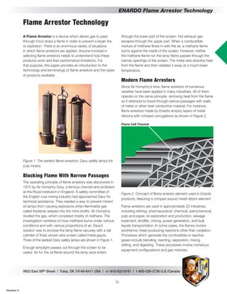
  • 1. 9932 East 58th Street | Tulsa, OK 74146-6411 USA | +1-918-622-6161 | 1-800-336-2736 U.S./Canada 15 ENARDO Flame Arrestor Technology A Flame Arrestor is a device which allows gas to pass through it but stops a flame in order to prevent a larger fire or explosion. There is an enormous variety of situations in which flame arrestors are applied. Anyone involved in selecting flame arrestors needs to understand how these products work and their performance limitations. For that purpose, this paper provides an introduction to the technology and terminology of flame arrestors and the types of products available. Figure 1. The earliest flame arrestors: Davy safety lamps for coal miners. Blocking Flame With Narrow Passages The operating principle of flame arrestors was discovered in 1815 by Sir Humphry Davy, a famous chemist and professor at the Royal Institution in England. A safety committee of the English coal mining industry had approached Davy for technical assistance. They needed a way to prevent miners’ oil lamps from causing explosions when flammable gas called firedamp seeped into the mine shafts. Sir Humphry studied the gas, which consisted mostly of methane. The investigation centered on how methane burns under various conditions and with various proportions of air. Davy’s solution was to enclose the lamp flame securely with a tall cylinder of finely woven wire screen called metal gauze. Three of the earliest Davy safety lamps are shown in Figure 1. Enough lamplight passes out through the screen to be useful. Air for the oil flame around the lamp wick enters through the lower part of the screen. Hot exhaust gas escapes through the upper part. When a combustible mixture of methane flows in with the air, a methane flame burns against the inside of the screen. However, neither the methane flame nor the lamp flame passes through the narrow openings of the screen. The metal wire absorbs heat from the flame and then radiates it away at a much lower temperature. Modern Flame Arrestors Since Sir Humphry’s time, flame arrestors of numerous varieties have been applied in many industries. All of them operate on the same principle: removing heat from the flame as it attempts to travel through narrow passages with walls of metal or other heat-conductive material. For instance, flame arrestors made by Enardo employ layers of metal ribbons with crimped corrugations as shown in Figure 2. Flame Cell Channel Figure 2. Concept of flame arrestor element used in Enardo products, featuring a crimped wound metal ribbon element Flame arrestors are used in approximately 22 industries, including refining, pharmaceutical, chemical, petrochemical, pulp and paper, oil exploration and production, sewage treatment, landfills, mining, power generation, and bulk liquids transportation. In some cases, the flames involve exothermic (heat-producing) reactions other than oxidation. Processes which generate the combustible or reactive gases include blending, reacting, separation, mixing, drilling, and digesting. These processes involve numerous equipment configurations and gas mixtures. Flame Arrestor Technology Revision A
  • 2. ENARDO | www.enardo.com 16 ENARDO Flame Arrestor Technology (Speaking non-technically, deflagration means rapid burning, and detonation means explosion.) These units are installed in pipes to prevent flames from passing, as shown in Figure 5. Figure 5. A typical Enardo in-line flame arrestor. Most in-line flame arrestor applications are in systems which collect gases emitted by liquids and solids. These systems, commonly used in many industries, may be called vapor control systems. The gases which are vented to atmosphere or controlled via vapor control systems are typically flammable. If the conditions are such that ignition occurs, a flame inside or outside of the system could result, with the potential to do catastrophic damage. One variety of vapor control systems is called vapor destruction systems. Included are elevated flare systems (Figure 6), enclosed flare systems, burner and catalytic incineration systems, and waste gas boilers. Figure 6. An in-line flame arrestor in a flare system. Another type of vapor control system using in-line flame arrestors is vapor recovery systems. Included here are vapor balancing, refrigeration, adsorption, absorption, and compression systems. End-Of-Line, Vent-To-Atmosphere Type Most flame arrestor applications and designs fall into two major categories. One group consists of end-of-line flame arrestors, also known as the vent-to-atmosphere type (Figure 3). Figure 3. End-of-line flame arrestors are used in applications such as petroleum storage tank vents. The classic application is in preventing fire in the atmosphere from entering an enclosure. Around 1920, for instance, flame arrestors began to be installed on vents on oilfield storage tanks. They keep the tanks from exploding when gas flowing from the vents is struck by lightning (Figure 4). Figure 4. Oilfield storage tank vents were an early application of industrial flame arrestors. Conversely, some end-of-line flame arrestors prevent fire in an enclosure from igniting an explosive atmosphere such as in a refinery. For instance, flame arrestors may be installed in furnace air inlets and exhaust stacks. The Davy lamp might be considered another example of that sort. In-Line, Deflagration Or Detonation Type The other major category consists of in-line flame arrestors, also known as deflagration and detonation flame arrestors. Revision A
  • 3. 9932 East 58th Street | Tulsa, OK 74146-6411 USA | +1-918-622-6161 | 1-800-336-2736 U.S./Canada 17 ENARDO Flame Arrestor Technology Figure 7. An in-line flame arrestor used in an end-of-line application (below a pressure and vacuum relief valve for a liquid storage tank). For example, the primary flame safety devices in a vapor control system are usually active ones such as liquid seals and oxygen analyzers as shown before in Figure 6. However, active devices can be rendered ineffective by loss of power, failure of mechanical components, failure of electronic communication, or human error. Flame arrestors, in turn, are the system’s secondary or fail-safe provision. In other words, if the active, primary method malfunctions, the passive, secondary method will be the last defense against an explosion. Flame Propagation The differences between the various types of flame arrestors are based mainly on the nature of the flame which is expected (especially how fast it moves) and on the expected intensity of the pressure pulse created by the flame. A flame is a volume of gas in which a self-sustaining exothermic (heat-producing) chemical reaction is occurring. The reaction is presumed to be oxidation, also known as combustion. To have a flame, three things must be present; oxygen (supplied by air), very high temperature (initially supplied by an ignition source) and a flammable gas mixed with the air in However, in-line flame arrestors are sometimes used in end-of-line applications. For instance, an in-line unit may be mounted below a tank vent valve on a liquid storage tank (Figure 7). The valve reduces emissions and product loss, while the flame arrestor protects the tank from flames in the atmosphere during venting of flammable gases. As technology throughout the world has become more complicated, safety products have also evolved to meet new requirements. Flame arrestors, in particular, changed immensely during the last decade of the twentieth century. As will be explained later, flames in pipes can reach much higher speeds and pressures than in the open atmosphere. Therefore in-line flame arrestors are now subdivided into three categories on that basis. Furthermore, special provisions are made for each of the three major groups of gases according to degree of flame hazard (also explained later)—NEC Groups B, C, and D. Thus, there are now as many as twelve different types of flame arrestors, as follows: 1. End-of-line, Group B 2. End-of-line, Group C 3. End-of-line, Group D 4. In-line, low/medium-press. deflagration, Group B 5. In-line, low/medium-press. deflagration, Group C 6. In-line, low/medium-press. deflagration, Group D 7. In-line, high-pressure deflagration, Group B 8. In-line, high-pressure deflagration, Group C 9. In-line, high-pressure deflagration, Group D 10. In-line, detonation, Group B 11. In-line, detonation, Group C 12. In-line, detonation, Group D In applying flame arrestors, it should be remembered that these safety devices are passive ones, and they are often used together with active safety devices. Active devices used in flame safety include hydraulic (liquid) seals, isolation valves, blankets of inert gas or enriching (fuel) gas, gas analyzers, and oxygen analyzers. Unlike active devices, passive devices such as flame arrestors do not depend on a power source, have no moving parts, and do not require human attention except to be cleaned periodically. Revision A
  • 4. ENARDO | www.enardo.com 18 ENARDO Flame Arrestor Technology propane’s UEL is 9.5%, and hydrogen’s is 75.0%. The flammable range of a gas is the difference between its lower and upper explosion limits. Hydrogen has a much wider flammable range than propane. A mixture with exactly the right amount of oxygen for complete combustion—no more, no less, producing the maximum energy per volume of gas—is called stoichiometric. Air-to-gas ratios at or near stoichiometric provide the highest flame propagation velocities and thus the most intense pressure impulse waves. However, as long as the mixture is well within the flammable range, the flame velocity ordinarily does not vary a great deal. Unconfined Propagation Of Flame Flames generally propagate much faster in pipes than in the open atmosphere. Flames which are not restricted by physical barriers such as pipes are called unconfined. An unconfined flame is free to expand by consumption of unburned gas into an ever-widening volume. This expansion provides quick dissipation of the heat and pressure energy generated by the flame. The most common example of unconfined propagation occurs when gas venting from a process system or liquid storage tank contacts an ignition source (Figure 8). From that point, flame propagates outward and towards the unburned gas until it comes to the gas source. Figure 8. Concept of an unconfined deflagration When the unconfined flame first begins to consume the unburned gas, the flame front travels below sonic velocity (the speed of sound in the atmosphere). If the velocity remains subsonic, the event is called a deflagration; the gas is said to deflagrate, meaning burn rapidly. By contrast, flame propagation at or above the speed of sound is called suitable proportions called a combustible mixture. So long as these requirements remain available, a flame can burn indefinitely. Flame arrestors operate by removing one of these requirements: high temperature. In a stationary flammable mixture, a flame seems to move toward the unburned gas, leaving combustion products behind. That apparent motion is called flame propagation. The flame exists only within a relatively narrow volume at the boundary between the unburned gas and the combustion products. The speed at which the flame propagates is measured at the front edge of the flame. This speed depends on several variables, including the speed of the chemical reaction, the air-to-gas mixture ratio, and whether the flame is confined or unconfined. Chemical Reaction Kinetics The speed of a chemical reaction, such as that between fuel gas and oxygen, is called its kinetics. This is determined mainly by the amount of energy released by each molecule of flammable gas when it combines with oxygen. For instance, hydrogen burns much faster than propane. Thus, given ideal air mixtures at room conditions, an open (unconfined) hydrogen flame propagates at 3 meters per second, compared to only 0.4 meters per second for propane. However, reaction speed also depends strongly on the temperature and pressure: the hotter a flame, and the higher its pressure, the faster the reaction that sustains it. Air-To-Gas Mixture Ratio Another determinant of flame propagation speed and pressure generation is the air-to-gas mixture ratio. A given flammable gas will sustain a flame only within a certain mixture range at a given pressure and temperature. If there is too little gas for a lasting flame at that condition, the mixture is said to be too "lean" to burn. In that case, the concentration (volumetric percentage) of gas in the air is below the lower explosion limit (LEL) for that particular gas. This is the concentration below which a flame will not last at that pressure and temperature. For example, the LEL at room conditions is 2.1% for propane and 4.0% for hydrogen. Conversely, if there is too little air, the mixture is too "rich" to burn. The upper explosion limit (UEL) for a particular gas is the concentration of gas above which a flame will die out at a given pressure and temperature. At room conditions, Revision A
  • 5. 9932 East 58th Street | Tulsa, OK 74146-6411 USA | +1-918-622-6161 | 1-800-336-2736 U.S./Canada 19 ENARDO Flame Arrestor Technology speeding the combustion reaction. This process feeds on itself, producing flame velocities, temperatures, and pressures much higher than those seen in unconfined conditions. Figure 9. Elements of flame propagation from the closed end of a pipe of indefinite length. To be more precise, suppose a pressure gauge capable of extremely quick response is placed 10 meters away from the ignited end. As the flame moves towards the gage, the reading increases. When the flame reaches the gage, it causes a pressure spike as high as 100 psig (7 bars) or higher. While propagating down a pipe, the flame functions not only as a chemical reaction, but also as a mechanical reaction—like a piston in a cylinder—compressing the gas before consuming it and im-parting more energy and velocity. If the pipe is long enough, in some cases the flame can reach hyper-sonic (much faster than sound) velocities as high as 6,500 miles per hour (2,900 meters per second). The pressure may approach 4,900 pounds per square inch (34,000 kilopascals). Development Stages Of Confined Flame Selection of an appropriate in-line flame arrestor depends on how intense any flame in the pipe is expected to be, in terms of velocity and pressure. Studies of flame propagation in pipes reveal seven distinct stages or phases which a flame may reach if the pipe is long enough and the combustion is fast enough and energetic enough. a detonation, which is an explosion strong enough to cause shock waves in the gas. Some gases can detonate without being confined, but it is not a common occurrence. As the subsonic flame moves in the direction of the unburned gas, it produces heat. The heat, in turn, expands the unburned gas in a layer in front of the flame, called the boundary layer. The rapid expansion of the boundary layer along with the fast-moving flame is commonly called an atmospheric explosion and percussion wave. The pulse of elevated temperature and pressure quickly spreads out and dissipates into the atmosphere in a relatively simple manner. Confined Propagation Of Flame The most common example of confined flame is propagation inside a pipe or explosion inside a process vessel or liquid storage tank. The flame is usually a flashback, meaning that it propagates upstream, against the flow of gas and towards its source. The heat and pressure energy of a confined flame is not relieved as readily as that of an unconfined flame. This restriction of energy dissipation makes a tremendous difference in how the flame propagates and thus what kind of flame arrestor is required to stop it. In a readily combustible mixture, the velocity of an unconfined flame depends primarily on the kinetics of the combustion reaction. Most of the combustion heat and resulting pressure are dissipated in the surrounding atmosphere, without influencing propagation speed very much. Confined flames also rely on the kinetics of burning for flame propagation velocity. However, since the flame is confined, the heat energy and pressure remain concentrated, causing a much stronger effect on the kinetics of burning and therefore the flame propagation velocity. More particularly, imagine a very long, straight pipe about six inches in diameter, closed by a cap at one end and filled with combustible mixture at room temperature and pressure. Suppose the gas is ignited by a spark plug at the closed end as suggested in Figure 9. A flame propagates in the unburned gas along the pipe. As described before for an unconfined flame, the heat of the flame expands the gas boundary layer directly in front, causing a pulse of pressure. However, the energy is not allowed to dissipate by spreading into an ever-widening region of atmosphere. Instead, as the flame propagates down the pipe, it encounters gas with higher temperature and pressure, Revision A
  • 6. ENARDO | www.enardo.com 20 ENARDO Flame Arrestor Technology gage pressure is less than about 100 kPag). This initial flame propagation state develops in a short length of pipe—for example, approximately 3 meters for a propane-air mixture. Hydrogen is in its low-pressure deflagration state only to about 1.0 meter from the point of ignition. (DP/Po is the dimensionless ratio for deflagration and detonation testing as measured in the piping system on the side of the arrestor where ignition begins. Po is the system initial absolute pressure. DP is the measured absolute pressure, minus Po.) Figure 12. Concept of medium-pressure deflagration confined in a pipe, showing typical distance from ignition point. Medium-Pressure Deflagration As the flame propagates farther down the pipe, its intensity increases to the dynamic state of medium-pressure deflagration. Flame speed is higher but still subsonic—up to 200 m/s. The pressure impulse at the flame reaches levels considered to be medium, with DP/Po up to 10. For a propane/air mixture beginning at room conditions, the flame is in this state when passing from about 3 to about 10 meters from the ignition point. Hydrogen, by comparison, is in its medium pressure deflagration state between 1.0 and 2.5 meters from ignition. Figure 13. Concept of high-pressure deflagration confined in a pipe, showing typical distance from ignition point. High-Pressure Deflagration Beyond the limit of medium-pressure deflagration, the propagating flame reaches the condition of high-pressure deflagration. The flame front velocity—still subsonic—is up to 300 m/s, and the pressure increase caused by the expanding boundary layer reaches a DP/DPo as high as 20. The distance from the ignition point is between 20 and 30 Figure 10. Conceptual graphs showing velocity and pressure of a flame front at points along a long pipe, beginning with ignition at a closed end. All scales are logarithmic. These stages are illustrated in Figure 10 by imaginary graphs of the speed and pressure of a flame at each point as it travels along a pipe of indefinite length. Note that the pressure is the transient peak that would be indicated by a very quick-response gauge at each point along the pipe. The flame reaches stages labeled A through F, one after another, at increasing distances from the ignition point. Figure 11. Concept of low-pressure deflagration confined in a pipe, showing typical distance from ignition point. Low-Pressure Deflagration So long as the flame front travels well below the speed of sound with minimal pressure increase caused by the expanding boundary layer, its condition is considered to be low-pressure deflagration (Figure 11). That stage is generally associated with velocities up to about 112 meters per second and relative increases of absolute pressure (DP/ Po) up to 1. (Assuming initial atmospheric pressure, the Revision A
  • 7. 9932 East 58th Street | Tulsa, OK 74146-6411 USA | +1-918-622-6161 | 1-800-336-2736 U.S./Canada 21 ENARDO Flame Arrestor Technology Figure 16. Concept of overdriven detonation confined in a pipe, showing typical distance from ignition point. Overdriven (Unstable) Detonation As the flame propagates even farther down the pipe, it goes into the dynamic state of overdriven or unstable detonation. This is defined as a flame front moving at supersonic velocity and in some instances at hypersonic velocity, attended by tremendous compression of gas by multiple shock waves. It is an unstable and transient condition. As the flame goes through DDT, it continues to pile shock waves into a dense concentration. Gas in front of the flame is compressed and heated above the ignition point like the fuel mixture in a diesel engine cylinder. When the compressed gas self ignites, the explosion releases an extremely large amount of energy, much like the earlier DDT. Again, the energy is restrained by the piping and only allowed to move straight ahead. Since the flame velocity is already supersonic, the flame accelerates to hypersonic velocities. The reason this condition is temporary is that the flame velocity and pressure are dependent on numerous shock waves providing gas compression in front of the flame. These shock waves dissipate soon after the initial explosion, and the velocity and pressure of the flame stabilize. An overdriven detonation has a typical peak velocity in the range of 2,300 m/s and a maximum impulse pressure of about 20,995 kPa(g)—equivalent to a DP/Po of 130. This flame propagation state develops in a pipe length beginning just beyond the DDT and ending approximately 60 meters from the ignition source for a propane/air mixture and 20 meters for hydrogen and air. Stable Detonation Beyond the transient overdriven detonation, the propagating flame finally reaches the dynamic state of stable detonation. The flame front moves at or above the speed of sound with shock-wave compression in front. The flame will not go through any more transitions but will remain in this stable condition to the other end of the pipe. A stable detonation has a velocity in the range of 300 m/s and a peak impulse pressure of 3,500 kPa(g), equivalent to a DP/Po of 20. meters for a propane/air mixture and between 2.5 and 6 meters for hydrogen and air. Figure 14. Concept of deflagration-to-detonation transformation in a pipe. Deflagration-To-Detonation Transformation When the propagating flame front passes sonic velocity, what occurs is called transformation from deflagration to detonation, abbreviated DDT. The pressure impulse in front of the flame becomes a shock wave. The compressed gas immediately in front of the expanding boundary layer of gas just in front of the flame, which can reach pressures around 700 kPa(g), comes in contact with the flame. The result is an explosion. The energy of that explosion, which includes heat, velocity, and pressure, has nowhere to go but down the pipe. The explosion generates tremendous shock-wave compression of the gases both upstream and downstream of the initial point of transformation. Figure 15. Concept of detonation confined in a pipe, showing typical distance from ignition point. Detonation A detonation is defined as a flame front moving at or above the speed of sound. It entails increased compression of the gases by shock waves in front of the flame. A detonation may have a velocity in the range of 300 m/s and a maximum impulse pressure of 3,500 kPa(g), with DP/Po as high as 20. This flame propagation state develops in a pipe length from slightly beyond the high-pressure deflagration up to approximately 30 meters beyond the ignition point for a propane/air mixture and approximately 10 meters for hydrogen in air. Revision A
  • 8. ENARDO | www.enardo.com 22 ENARDO Flame Arrestor Technology If the gas feeding a flare or waste gas burner slows down below the burn-back velocity at the flare tip or burner, then the flame moves upstream toward the process source. If the gas velocity is only slightly lower than the burn-back velocity, the flame will creep slowly upstream. However, at zero gas velocity in a long pipe, the flame will accelerate as explained before and flash back at high speed. Zero flow allows the most severe flame propagation conditions. All flame arrestor products should be tested by the manufacturer at static (zero) flow so that they will work in the most severe flame propagation conditions (flashback). Initial Operating Pressure (IOP) The initial operating pressure (IOP) is the absolute pressure of a flammable gas mixture in a given piping system when the velocity falls below the burn-back velocity. The IOP is usually less than the normal operating pressure of that system. For example, when a vapor control system is operating properly, so that the flow stream velocity is above the burn-back velocity of the process gas, then the system pressure is within some normal operating range above atmospheric pressure. But when the system is shut down during normal or emergency conditions and the process stream slows down, the pressure also falls. At some point before the velocity reaches zero, a flashback can occur. The pressure in the system in this shutdown situation or static flow condition is the IOP for that particular system. Remember that pressure affects flame: the higher the pressure, the more energy the flame releases per unit volume. That equates to higher flame intensity and energy exchange per unit volume and faster flame acceleration. The explosive pressure of a given gas is roughly proportional to the initial absolute pressure. For instance, doubling the absolute pressure approximately doubles the explosive pressure. Therefore, the IOP in a given system determines two things pertaining to selection of a flame arrestor product. The first is flame velocity and pressure relative to the distance the flame has traveled down the pipe. For example, when a flame has propagated 10 meters in a stoichiometric propane-to-air mixture at atmospheric pressure (101.3 kPa absolute), the flame velocity is approximately 200 m/s, and the pressure front is at about 800 kPa absolute. If instead the IOP is increased to 150.0 kPa, the flame velocity and pressure at 10 meters will be approximately 300 m/s and 1,200 kPa. Thus, in this example, increasing the static pressure 50% causes an increase of 50% in the velocity of Figure 17. Concept of stable detonation confined in a pipe, showing typical distance from ignition point. Galloping Detonation A detonation that periodically fails and reinitiates during propagation is known as a galloping detonation. “This type of detonation is typically observed in near-limit mixtures (they have been observed near the lean and possibly near the rich limit). Since it reinitiates via DDT, a galloping detonation is periodically overdriven and results in large overpressures at periodic distances along a pipe. Over these periodic cycles the wave oscillates between a fast deflagration and a leading shock, transition to an overdriven detonation, and a short lived apparently steady detonation phase.”1 Selection Considerations For In-Line Flame Arrestors Selecting an appropriate in-line flame arrestor for a given application requires understanding several considerations. These considerations are based on the foregoing general understanding of how an accidental gas flame behaves in pipes. Burn-Back Gas Velocity When a flammable mixture is flowing in a pipe, one especially important condition is the burn-back gas velocity. It is the gas velocity at which a flame is stationary when propagating upstream in a condition of low-pressure deflagration. This refers to the "superficial" average gas velocity across the pipe—the volumetric flow rate divided by the crosssectional flow area. If the gas flows slower than the burn-back velocity, a flame can propagate upstream. The burn-back velocity depends on the type of gas and its air-to-gas mixture ratio as well as the temperature and pressure. At stoichiometric mixture and standard room conditions, propane’s burn-back velocity is approximately 3.2 m/s, whereas hydrogen’s is approximately 20 m/s. 1 Grossel, Stanley, Deflagration and Detonation Flame Arresters (AIChe, 2002), 66. Revision A
  • 9. 9932 East 58th Street | Tulsa, OK 74146-6411 USA | +1-918-622-6161 | 1-800-336-2736 U.S./Canada 23 ENARDO Flame Arrestor Technology Flame Stabilization There are two types of flame stabilization: open and confined. An open stabilized flame occurs when a flammable mixture emerges from confinement at a velocity such that an open flame fed by the gas is stationary. For example, when a flare is burning, the stationary flame at the tip experiences open flame stabilization. If for some reason the process stream slows down below the burn-back velocity of the gas, the flame begins moving down the flare stack. It may then stabilize at the arrestor device or somewhere else down the pipe. This condition is referred to as confined flame stabilization. (See Figure 18.) If the process stream velocity were to go to zero, the flame would not creep down the flare but would accelerate in a flashback and possibly detonate. The possibility for a stabilized flame in the system during flashback is very slight, but it sometimes happens. Each flame arrestor design performs differently when exposed to flame stabilization, depending on the mass and type of material of the flame-arrestor element. Users should contact the manufacturer of a given arrestor for information on how its products perform when exposed to flame stabilization. A good way to safeguard against flashback due to flame stabilization is to install a temperature sensing device on the exposed side of the arrestor. The heat of a stabilized flame triggers automatic controls designed to extinguish the flame. Flame stabilized on arrestor element Exposed side Protected side Piping Flame arrestor element absorbs and quenches flame front Figure 18. Concept of flame stabilization at aflame arrestor. Flow is from right to left. Air-To-Fuel Mixture Ratios The ratio of combustible gas to air, described earlier, has a profound effect on how a flame burns. It influences not only flame speed as mentioned before, but also heat intensity, ignition energy, auto-ignition temperature, pressure piling, and others. the flame front and 50% in its pressure. This consideration can affect how close to the ignition source the arrestor must be placed. It can also require the use of one arrestor device rather than another. The second selection consideration affected by IOP pertains to the energy which an arrestor must absorb per unit volume of gas in order to quench a flame. When pressure increases in a process system, the energy released by flame per unit volume also increases. Thus the arrestor must absorb more heat to lower the flame’s temperature sufficiently. However, that task can be difficult for the arrestor, since it was designed with a certain heat transfer capacity. If an arrestor is placed in an application for which the IOP is higher than it has been tested or designed for, the arrestor could fail to stop the flame. Therefore, to enable proper selection and system design, manufacturers must indicate the maximum IOP which their flame arrestors can handle for various flammable gas mixtures. Every flame arrestor product should be tested at a series of increasing pressures to determine its IOP performance threshold for commonly encountered gas mixtures. For example, a standard low-pressure deflagration arrestor typically has a maximum allowed IOP of around 5% above atmospheric condition, or 106.0 kPa (15.4 psia), while that for detonation flame arrestors ranges up to 160 kPa (23 psia). Transient Momentum Pressure Piping can withstand a propagating flame driving a pressure pulse which may be thousands of times greater than the maximum pressure for which the pipe is rated. This pressure caused by flame propagation is not a static pressure, because the pressure wave is moving so fast it exerts its force on the piping walls for only a fraction of a second. Instead, flame pressure is considered a dynamic impulse pressure, called transient momentum pressure or TMP. Because the transient motion of gas in the forward direction is so rapid when a pressure wave passes, the wave carries a tremendous amount of momentum (mass multiplied by velocity) and resulting energy (one-half of mass multiplied by the square of velocity). Anything which changes the direction of that momentum, such as pipe bends, shut-off valves, blower housings, or an arrestor device, experiences transfer of energy via momentum. This momentum energy can have a catastrophic effect on equipment. Standard flame arrestors are designed for low transient momentum pressures (TMPs) and can fail mechanically when exposed to very high TMPs. Enardo detonation arrestors are designed to withstand TMPs of any magnitude. Revision A
  • 10. ENARDO | www.enardo.com 24 ENARDO Flame Arrestor Technology immersed in a stoichiometric mixture of the test gas and air at standard room conditions, and the mixture inside the sphere is ignited with an electric spark. The experiment is repeated with a wider and wider gap between the two flanges, until the mixture outside the sphere is ignited. The MESG is the greatest distance between flanges at which the flame fails to pass through. The more hazardous the gas, the narrower the MESG. An arrestor must be designed for the MESG value of the process gas. Multiple Gas Mixtures Some vapor collection systems deal with a single, relatively pure combustible gas—for instance methane or acetylene— mixed with air. However, most processes requiring flame arrestors involve mixtures of several combustible gases, each having its own set of hazard characteristics. Some gases consume air more efficiently than others in a mixture, thus making the mixture behave much like a single constituent gas. One gas component may act as a catalyst to another, making the mixture more dangerous than the single most hazardous gas by itself. Not much experimental data is available on the hazardous characteristics of combustible gas mixtures. The MESG of mixed gases is not normally known and it is impractical to test all gas mixtures for their MESG. The industry standard has been to select an arrestor design based on the worst case gas component in the mixture. This method is in most cases, overly conservative. NFPA 497 provides a new method to estimate the group classification based on knowing the MESG of each flammable gas component and calculating the effective MESG by applying a form of Le Chatelier’s relationship. Enardo can assist you with this calculation if provided the gas mixture composition. Auto-Ignition Temperature (AIT) AIT is the temperature at which a stoichiometric mixture of a combustible gas at standard atmospheric pressure will ignite. Propane’s AIT is 493°C, Hydrogen’s is 560°C, and ethylene’s is 425°C. An arrestor works by cooling the gas below its AIT. Therefore, if the process is operating close to the AIT of the gas, this initial heat may affect the performance of the arrestor. It is very important that the process temperature be stated to the manufacturer when selecting an arrestor. Grouping Of Gases Hundreds of different flammable gases are generated as products or by-products of industrial processes. One gas may vary widely from another in its characteristics pertaining to flame propagation. It is necessary to have means for describing those characteristics in order to design safety equipment, instrumentation, etc. Several testing and regulatory bodies, including the NEC, IEC, NFPA, and NTIS, classify flammable gases based on the following criteria, some of which are explained later: MESG (maximum experimental safe gap) Flame temperature Flame velocity AIT (auto-ignition temperature) LEL-to-UEL range Ignition energy NEC IEC MESG Test Gas List Group A 0.25 Acetylene Group B Group IlC 0.28 Hydrogen Group IIB 0.50 Enriched H2 Group C Group IlB3 0.65 Ethylene Group D Group IIA 0.90 Propane G.M 1.15 Methane Table 1. Hazardous gas groups according to NEC and IEC Each testing or regulatory authority has its own system for classifying gases according to combustion hazard groups. Classifications are based on severity of explosion hazard as indicated by low AIT, broad LEL-to-UEL range, higher flame temperature, faster flame velocity, or a combination of any of these characteristics. Most of them relate directly to the MESG of the combustible gas. (See Table 1.) Maximum Experimental Safe Gap (MESG) Maximum experimental safe gap is a standard measurement of how easily a gas flame will pass through a narrow gap bordered by heat-absorbing metal. MESG was developed to classify gases for design and selection of electrical instrumentation, electrical enclosures, and flame arrestor devices. The measurement is conducted with a standard apparatus consisting of a small, hollow metal sphere of a certain diameter which is split into two halves. The circular edge of each hemisphere is provided with a smooth metal flange of a certain width. The hemispheres are held close together in the apparatus with the flanges parallel and separated by a narrow gap. This apparatus is Revision A
  • 11. 9932 East 58th Street | Tulsa, OK 74146-6411 USA | +1-918-622-6161 | 1-800-336-2736 U.S./Canada 25 ENARDO Flame Arrestor Technology The ignition energy is defined as the amount of energy required to ignite a flammable gas mixture. That amount depends on the type of gas and the air-to-gas mixture ratio. The closer the air-to-gas ratio is to stoichiometric, the lower the ignition energy. This is illustrated in Figure 19. In that diagram, note that the energy required to ignite methane at stoichiometric is 0.2 joules, compared to the energy required at its UEL, which is 3.5 joules. Different gases require different amounts of energy to ignite them; some require little, while others are almost impossible to ignite. The lower the ignition energy, the more dangerous the gas is to the system and its surroundings. Methane, volume - percent SparkEnergy,watt-sec Figure 19. The ignition source is the starting point for measuring the most important variable for flame arrestor selection, which is the distance to the arrestor. Therefore the user must know the locations of all potential ignition sources relative to the arrestor. High-Energy Ignition Typical ignition sources have energy levels which are considered to be low, meaning just enough energy to ignite the combustible gas mixture. A high-energy ignition source, on the other hand, can cause the flame to be in a more severe state of propagation within a given length or L/D ratio than a low-energy source. The flame can actually skip the low, medium, and high-pressure deflagration states and jump directly into detonation. Such behavior represents an exception to the conventional theory of flame propagation which was outlined earlier here. There are no established standards to differentiate between normal ignition energy and high-energy ignition. However, lightning strike, vessel explosion, and burner chamber explosion are all considered to be high-energy ignitions. Since a high-energy ignition changes the way a flame propagates, the rules for selecting a flame arrestor product also change. For example, consider a deflagration flame arrestor in a typical flare application for which it is designed—a Length To Diameter (L Over D) Ratio In explaining the various stages of flame propagation earlier, each stage was said to occur within a certain range of distances from the ignition source. Those distances were specified for a certain inside pipe diameter of 12 inches. It turns out that the distances are directly proportional to the diameter. What matters is not the actual distance from the ignition point, but the distance relative to the diameter—the distance divided by the diameter. That relative distance is called the length-to-diameter ratio, or the L/D ratio (L over D ratio). For example, for a stoichiometric air-propane mixture at room conditions, a low-pressure deflagration will occur within an L/D ratio less than 10, and a stable detonation will usually occur at L/D ratios greater than 60. All arrestors except the unstable detonation types have L/D performance limitations. Information on these limitations must be obtained from the manufacturer. Pipe Configuration And Restrictions How a flame burns and propagates is affected not only by the length of a pipe, but also by bends, instrumentation (metering runs, restrictive orifices, thermowells, etc.), pipe contractions and expansions, valves, etc. Anything which increases turbulence of the gas gives the flame a more uniform air-to-gas mixture, thus enhancing combustion. In addition, as mentioned before, transient momentum acts on piping irregularities. Gas expansion caused by burning acts as thrust propulsion when given a surface on which to apply the force of expansion. The flame cannot exert a thrust force on smooth, straight pipe. However, when it travels past a bend or restriction, it can exert a force on this surface area, giving it a forward velocity and pressure boost. Each arrestor design has been tested to protocols which may or may not include bends and restrictions. The manufacturer should be consulted before installing any arrestor in a system with bends or restrictions. Ignition Source And Energy Accidental gas ignition can be caused by such things as static discharge, sparks from a blower impeller hitting the blower housing, instrumentation, pilot flame for a flare or burner, main flame on the flare tip or in the burner chamber, hot work within a plant, external fire, and many other origins. These ignition sources can cause a flame inside or outside a process system. Revision A
  • 12. ENARDO | www.enardo.com 26 ENARDO Flame Arrestor Technology 2. Flame stabilization performance characteristics of the arrestor compared to the system potential for flame stabilization for sustained periods of time 3. Process gas temperature 4. Pressure drop across the arrestor during venting flow conditions, relative to the system's maximum allowable pressure and vacuum 5. Materials of construction that meet the ambient and process conditions – for example, extremely cold climate, salt spray, chemically aggressive gas, etc. 6. Connection type and size 7. Instrumentation requirements Selecting In-Line Flame Arrestors The various dynamic states explained earlier for confined flames can be very dangerous for a process system due to the tremendous energies associated with detonation pressure and flame velocity. Things happen fast and can turn catastrophic. These multiple dynamic states increase the challenge of providing a flame arrestor product or products which stop the flame and withstand the enormous pressures caused by explosions within the confined piping. The very wide range of possible behavior for a confined flame causes two particular problems for flame arrestor products. First, the high-pressure deflagration and stable detonation states have very stable kinetics of burning, and the flame is moving very fast. Therefore the arrestor must be able to absorb the flame’s heat much faster than is required by standard low-to-medium-pressure deflagration conditions. Second, the instantaneous impulse pressures caused by the shock waves of overdriven detonation subject the arrestor to forces of up to 20995 kPa(g) (3000 psig). Thus, the arrestor must be structurally superior to standard low-pressure deflagration arrestors. Confined Deflagration Flame Arrestors In-line deflagration flame arrestors are designed for confined flame propagation, also referred to as flashback or confined deflagrations. Like the end-of-line variety, flame arrestors of this type have been used in numerous applications for many decades. They resemble end-of-line flame arrestors in many ways. However, things are much different for these arrestors, because they are subject to more severe flame states. For almost every state of flame, there is a special type of arrestor. For example, a standard in-line deflagration flame arrestor is designed to stop flame propagation in short lengths of pipe, involving low-pressure and medium-pressure deflagrations. The high-pressure deflagration flame arrestor is an enhanced 20-foot stack for a group "D" gas with flame arrestor near the base of the flare. If the process stream velocity falls below the burn-back velocity of the gas at the tip, a flashback could occur. Since the length of pipe from the tip of the flare (ignition source) to the arrestor is relatively short, the flame dynamics will probably be no more severe than a medium-pressure deflagration, and thus the deflagration flame arrestor will quench the flame. However, if the flare is struck by lightning (high energy ignition) while the flow is below burn-back velocity, the flame could be in a more severe state when it reaches the flame arrestor, such as high-pressure deflagration or overdriven detonation. In that case, the flame arrestor will probably fail, because it is not designed for a high-pressure deflagration or detonation. If there is a chance for high-energy ignition, an unstable detonation flame arrestor should be used instead of a standard deflagration flame arrestor. Enriched Oxygen In most vapor control systems, the source of oxygen in the combustible mixture is ambient air. However, some processes have a larger content of oxygen than standard air-gas mixture. Passive flame arrestor products discussed here are not designed for the more dangerous and severe condition of enriched oxygen. Dust Versus Gas When pulverized into dust suspended in air, combustible solids burn, propagate in piping, and explode much like combustible gases. Passive flame arrestor products discussed here are not designed for use with flammable dust suspensions because of special concerns such as plugging. Selecting End-Of-Line Flame Arrestors As explained before, end-of-line deflagration flame arrestors are designed for unconfined flame propagation, also referred to as atmospheric explosion or unconfined deflagration. They simply bolt or screw onto the process or tank connection. These designs incorporate well-established but simple technology. Most use a single element of crimped wound metal ribbon that provides the heat transfer needed to quench the flame before it gets through the arrestor element. The main points of concern when selecting an arrestor for end-of-line applications are as follows: 1. Hazardous group designation or MESG value of the gas Revision A
  • 13. 9932 East 58th Street | Tulsa, OK 74146-6411 USA | +1-918-622-6161 | 1-800-336-2736 U.S./Canada 27 ENARDO Flame Arrestor Technology These capabilities do not come without some trade-offs. Detonation flame arrestors impose higher pressure drops than deflagration flame arrestors due to heat-transfer requirements, they are heavier because of structural requirements, and they are typically more expensive. Therefore in-line deflagration flame arrestors will always have a place in industry. The main points of concern when selecting an arrestor device for in-line applications are the same as listed before for end-of-line applications, except for one additional consideration: the L/D ratio and piping configuration between the arrestor and the potential ignition source. version of the standard deflagration flame arrestor, designed to stop flames in the low, medium, and high pressure deflagration states. Figure 20. An Enardo detonation flame arrestor Detonation Flame Arrestors Enardo has offered a line of detonation flame arrestors since the early 1990’s. These detonation arrestors were developed and tested in accordance with the requirements of Appendix-A to Part 154 of 33 CFR, commonly called the "U.S. Coast Guard Standard"(USCG). These arrestors received USCG approval in 2" through 20" sizes, concentric and eccentric designs, with models for Group-D (IIA) and models for Group-C (IIB3) flammable vapors. Detonation arrestors approved to this standard must pass both stable and unstable detonations in addition to meeting other requirements, in other words, the most severe flame stage. There is no provision in this standard for detonation arrestors that are approved for stable detonations only. Enardo used the "U.S. Coast Guard Standard" as a guideline, when developing a detonation flame arrestor for the European market. EN 12874 does allow detonation arrestors to be classified for stable detonations only, however, Enardo believes that determining the location where the flame propagation transitions to a stable detonation is unpredictable. During testing in a controlled system all phases of flame propagation can be mapped. But in real life there are many variables,(fuel mixtures, temperature, pressure, pipe layout etc) which may lead to a situation where a galloping detonation may occur. Our belief is that the state of a detonation is unpredictable and therefore only those DFA’s approved for unstable detonations should be specified. None of the deflagration arrestor designs can withstand a detonation. Therefore the detonation flame arrestor was designed. (See Figure 20.) It has the heat transfer capacity and structural design to withstand all the dynamic conditions of flame propagation and still stop the flame. The detonation flame arrestor is the ultimate flame-stopping product and is used when the flame can be in any of the detonation states. Revision A
  • 14. ENARDO | www.enardo.com 28 ENARDO Flame Arrestor Technology Gas Group Chart (As defined by NFPA 321, NEC, IEC) Group A Acetylene Group B (IIC) Butadiene Ethylene oxide Formaldehyde Hydrogen Manufactured gases containing more than 30% Hydrogen (by volume) Propylene oxide Propyl nitrate Group C (IIB3) Acetaldhyde Cyclopropane Diethyl ether Dimethyl hydrazine Ethylene Hydrogen sulfide Methanol (methyl alcohol) Methyl mercaptan Tetrahydrofuran Unisymmetrical dimethyl hydrazine (UDMN) Group D (IIA) Acetone Acrylonitrile Ammonia Benzene Butane Butylene 1-Butanol (butyl alcohol) 2-Butanol (secondary butyl alcohol) Cyclohexane N-Butyl acetate Group D (continued) Isobutyl acetate Ethane Ethanol (ethyl alcohol) Ethyl acetate Ethyl acrylate Ethylene dichloride Gasoline Heptanes Hexanes Isoprene Methane (natural gas) Methyl acrylate Methylamine Methyl Ethyl Ketone 3-Methyl-1-Butanol (isoamyl alcohol) Methyl Isobutyl Ketone 2-Methyl-1-Propanol (isobutyl alcohol) 2-Methyl-2-Propanol (tertiary butyl alcohol) Naphtha (petroleum) N-Propyl acetate Octanes Pentanes 1-Pentanol (amyl alcohol) Propane 1-Propanol (propyl alcohol) 2-Propanol (isopropyl alcohol) Propylene Styrene Toluene Turpentine Vinyl acetate Vinyl chloride Xylenes * *Enardo recommendation Revision A