SlideShare uma empresa Scribd logo
1 de 4
Baixar para ler offline
26 www.aiche.org/cep November 2009 CEP
Back to Basics
The activated sludge process is used to treat
waste streams that are high in organics
and biodegradable compounds. Here are
some principles of design and operation.
Mark Sustarsic
Tetra Tech NUS
Wastewater Treatment:
Understanding the
Activated Sludge Process
T
he activated sludge process (Figure 1) uses a mass of
microorganisms (usually bacteria) to aerobically treat
wastewater. Organic contaminants in the wastewater
provide the carbon and energy required to encourage micro-
bial growth and reproduction; nitrogen and phosphorous are
sometimes added to promote this growth. The wastewater
is thoroughly mixed with air in an aeration tank, and the
organic matter is converted into microbial cell tissue and
carbon dioxide.
The microbial mass together with the wastewater is
referred to as a mixed liquor. After a specified time in the
aeration tank, the mixed liquor passes into a settling tank, or
clarifier, where the biomass, or sludge, settles by gravity from
the treated wastewater. This continuous process produces an
effluent that may be treated further or discharged directly to a
publicly owned treatment works (POTW).
The activated sludge process was developed in the early
1900s for the treatment of domestic wastewaters, and it has
since been adapted for removing biodegradable organics from
industrial wastewaters. Today, it is widely employed in the
treatment of both municipal and industrial wastewaters.
Applicability — chemicals, concentrations, facilities
Activated sludge treatment is suitable for use at facilities
that have organic chemical waste. These may include munici-
pal sewage-treatment plants, oil refineries, pulp and paper
mills, food processing plants, and chemical manufacturing
facilities.
When properly designed, the activated sludge process
provides good treatment for wastes containing biodegradable
compounds. It is generally used to treat biodegradable organic
wastewaters of moderate (10–1,000 ppm) to high (>1,000
ppm) strength. Performance varies depending on the specific
chemicals present and their concentrations, as shown in Table
1. The results in Table 1 are based on laboratory-scale testing
and should be considered only as guidelines for developing
pilot-scale and full-scale studies.
Activated sludge treatment is not intended to remove met-
als or dissolved or suspended solids. A rather high concentra-
tion (>100 ppm) of organics is needed to maintain proper
operation. Low-strength industrial effluent and moderate-
strength domestic wastewater may be combined for treatment
to achieve the required concentration. Wastewater containing
a wide variety of biodegradable organics can be treated by the
activated sludge process, as long as the concentration is in the
Table 1. The performance of activated sludge
treatment varies with the type of chemicals in
the waste being treated.
Chemical Type Treated
Typical Feed
Concentration, ppm
Typical
Removal
Phenolics (aromatic –OH) 100 to 1,000 >99%
Polynuclear Aromatic
Hydrocarbons (PAHs)
0.01 to 1 >95%
Oil and Grease 10 to 100 40 to 92%
Total Organic Carbon
(TOC)
500 to 3,000 >90%
Ammonia (–N) 10 to 1,000 >95%
Cyanide, Thiocyanide 1 to 1,000 40 to 98%
Metals
(arsenic, mercury, zinc)
0.5 Settles with
sludge
Benzene, Toluene, Xylene
(BTX)
5 to 1,000 >99%
CEP November 2009 www.aiche.org/cep 27
hundreds of parts per million.
Many remediation sites require the treatment of ground-
water, surface water, or landfill leachate with very low organic
concentrations, typically less than 10 ppm. This is not high
enough to sustain the biological mass needed, and such
streams are more appropriately treated by ozone, ultraviolet
light, trickling filters, and/or API separators. Some plants
combine groundwater, boiler blowdown and stormwater
runoff with process wastewater and feed the combined stream
to an activated sludge treatment facility.
The process
Before it enters the aeration basin, raw wastewater (influ-
ent) is normally pretreated to remove easily settled solids
or other suspended matter, such as oil. Raising the pH will
slightly solidify iron and zinc (if present). A steam or air
stripper can remove ammonia, phenol, and any light ends,
while a filter removes heavy particulates. Because substan-
tial changes in the incoming water characteristics will cause
a process upset, an equalization tank is sometimes included
in the pretreatment system to achieve the required design
inlet conditions, such as a certain flowrate or chemical
concentration.
The pretreated influent is pumped into the aeration tank
(or basin), where it is combined with the microorganisms.
In order to maintain the bacterial mass in the aeration basin,
aerators perform two important functions: they keep the liquid
and sludge agitated, and they promote the transfer of oxygen
into the wastewater. The aerators run continuously and are
strategically positioned to keep the mixed liquor in suspension
throughout and avoid the formation of dead zones. Foam gen-
erated by the aerators can be contained by anti-foam sprays.
The pH of the incoming wastewater or mixed liquor
must be steadily controlled for proper microorganism
growth. A neutral pH is maintained by adding a caustic or
acid, usually 25% by weight in solution. Supplemental nutri-
ents in the form of nitrogen (urea) and phosphorus (phos-
phoric acid) are added on an as-needed basis, such as when
the raw wastewater is an insufficient source of required
nutrients.
In colder climates, supplemental heat is required to main-
tain an acceptable temperature range for the microorganisms.
Indirect heat is added to the base of the aeration basin via a
steam bayonet or a gas-fired heater. Some plants save energy
by first preheating the influent with a hot process stream
(e.g., distillation column bottoms) in a heat exchanger.
After spending a specified amount of time in the aeration
basin, water overflows into a clarifier, where the microbial
solids settle by gravity and are separated from the treated
water. The clarifier consists of a tank with a center feed well,
which promotes even dispersion. The settled sludge is raked
from the quiescent zone at the bottom of the clarifier with
mechanical scrapers. A portion of the biomass is recycled
back to the aeration basin to maintain the desired concen-
tration of organisms in the basin. The remaining sludge is
pumped from the system, typically by a motor-driven cen-
trifugal pump equipped with a flowmeter, for final disposal.
Floating materials that collect at the surface of the liquid in
the clarifier are collectively referred to as scum. A skimmer
constantly moves the scum toward a collection trough that
drops it into a receiver for later removal. Both the sludge
scraper and the scum skimmer are connected to a common
Figure 1. Conventional activated sludge systems process raw influent in the aeration tank before sending it to the clarifier for settling.
Oxygen Supply
Supplemental Heat
(if required)Slude Disposal
or Reuse
Recycle
Sludge
Waste Sludge
Additional Treatment
(Thickening,
Dewatering, etc.)
(if required)
Disposal
Final Settling
(Clarified)
Treated Effluent to:
– Additional
Treatment
(Chlorination,
Filtration, etc.)
– Disposal
(POTW, Surface
Water, etc.)
– Reuse
Raw Influent
Pretreatment is Usually Required
to Remove Suspended Materials,
Oils, etc. by Primary Settling
and/or Other Physical Means
Surface and/or
Deep Impellers
Supplemental Nutrient
(N, P) Addition
(if required)
pH Control
(if required)
Aeration
Tank
28 www.aiche.org/cep November 2009 CEP
Back to Basics
drive shaft powered by a small motor.
Clean water travels to the outside edge of the clarifier
and is discharged under a baffle and over a notched weir that
extends around the periphery. The concentration of total sus-
pended solids (TSS) in the effluent discharge is low, 10–100
ppm. This water may go to a POTW, be discharged as surface
water in accordance with a National Pollutant Discharge
Elimination System (NPDES) permit, or receive tertiary treat-
ment such as by activated carbon adsorption.
Wasted sludge from the bottom of the clarifier is thick-
ened, typically in a vacuum filter press, prior to its ultimate
disposal. The degree of wasting determines the solids reten-
tion time (SRT) of the system. At a low wasting rate, the
SRT would be relatively high — i.e., the solids remain in the
system longer.
System design
Table 2 lists key design parameters that are determined by
lab tests and past experiences.
The first design methods were formulated based on the
retention time of the wastewater in the aeration basin. Gener-
ally, short hydraulic retention times (HRT) were chosen for
weak (dilute) wastewaters and long HRTs were chosen for
strong (concentrated) wastewaters. HRT (measured in days)
is defined as the aeration tank volume (V, gal) divided by the
discharge rate (Q, gal/d):
HRT = V/Q (1)
Typical HRTs range from 1–5 d for municipal waste to
1–10 d for industrial waste.
Around 1970, other design parameters were developed
using fundamental scientific concepts, such as mass balance
and microbial growth kinetics. Although design equations
ultimately serve as the primary basis for the design of an
activated sludge system, pilot plant and/or laboratory tests
are essential for developing the design criteria. The resulting
design reflects the reaction rates, settling rates, solids reten-
tion time, and oxygen requirements for a particular type of
wastewater. The rate equations somewhat resemble those
used by chemical engineers to describe reactor kinetics, sug-
gesting that an aeration tank may be envisioned as a biologi-
cal “reactor.”
The solids retention time is an important design factor and
provides a theoretical indication of how long the microorgan-
isms remain in the aeration tank. Since these microorganisms
normally reproduce more quickly than they die, some acti-
vated sludge must be removed, or blown down, via a recycle
line. Blowdown, also called sludge wasting, should be carried
out daily to maintain the proper SRT. Without such wasting,
the mass of sludge could build up in the settling tank (clari-
fier) until solids overflow into the effluent.
The SRT (in days) is a function of the aeration tank volume
(V, gal), the sludge wasting rate (w, gal/d), and the concentra-
tions of suspended solids in the mixed liquor in the aeration
tank (MLTSS, g/L) and in the recycle line (MLTSSr, g/L):
SRT = (V × MLTSS) / (w × MLTSSr) (2)
SRTs for municipal wastewater treatment range from
Table 2. Typical characteristics of wastewater
can be addressed in the design process
by examining these variables.
Wastewater
Characterization Design Variables
Flowrate Hydraulic Retention Rime (HRT)
Water Quality Solids Retention Time (SRT)
Toxic or Inhibitory
Compounds
Recycle Ratio (r)
Optimization of HRT, SRT and r
Oxygen Requirements
Bacterial Growth and Decay Factors
Sludge Settling Factors
Table 3. When upsets occur, follow these suggested guidelines.
Problem Probable Cause Remedy
Low or high pH in the aeration basin Extremely high or low pH in influent Add alkali or acid to the aeration tank
No biological activity Reduce high concentrations of phenols and
oils, or add phosphorous or dissolved oxygen
to the aeration tank
Low dissolved O2 (DO) concentration in
the aeration tank
Influent feed rate is too high or has slug of
organics
Reduce feed until DO concentration goes
above 1.0 mg/L
Concentration of total suspended solids in
the mixed liquor (MLTSS) is too high
Lower SRT by wasting more sludge
High total suspended solids (TSS)
concentration in POTW
Presence of unwanted bacteria Increase DO or reduce influent organics by
reducing feed flowrate
Clarifier is overloaded Determine whether the recycle ratio and feed
rates are properly set
CEP November 2009 www.aiche.org/cep 29
5 to 20 d, whereas SRTs for industrial waste range from
20 to 1,000 d.
Another important design factor is the recycle ratio, r:
r = q/Q (3)
where q is the recycled sludge flowrate (gal/d) and Q is the
influent wastewater flowrate (gal/d). Recycle ratios are gener-
ally 0.5–3.0 for both municipal and industrial wastewater
treatment plants.
HRT, SRT and r are interrelated and are the most impor-
tant design variables. Combined with sludge settling charac-
teristics, they determine the size of the aeration basin, sludge
settling tank, and related pumps. The recycle ratio also affects
the size of the clarifier.
Other important factors that determine the final design
include the bacterial growth coefficient (Y) and the decay
coefficient (b), each of which may be determined through
laboratory treatability testing. The bacterial growth coef-
ficient is defined as the mass of bacteria produced per mass
of chemical consumed, and it has a value between 0.1 and
0.5. The b coefficient indicates the decay rate of the bacterial
organisms. Typical values range between 0.01 and 0.05 d–1.
The decay rate does not have as much influence on waste-
water treatment system design as the bacterial growth rate.
Operating conditions
Operation of an activated sludge process relies on
maintaining an acceptable environment for microbial activity
through routine monitoring and preventive maintenance, and
on the ability to survive any process upsets. The following
performance considerations may be relevant daily, weekly or
monthly.
Effluent. Limits on effluent water quality are determined
by the state or local environmental agency. The NPDES per-
mit generally specifies the allowable discharge flowrate, pH,
total organic carbon (TOC, mg/L), and TSS (mg/L).
Influent. To ensure smooth operations and avoid upsets,
the plant should maintain the influent flowrate, temperature,
pH, and concentrations of TOC, TSS, oil and grease, and
phenol (which can cause microbial shock) within specified
ranges. Values that exceed design limits indicate that pretreat-
ment modifications are necessary. For example, excess oil
and grease in the incoming water may indicate that the API
separator polymer-addition step needs to be modified.
Mixed liquor in the aeration tank. The aeration tank must
maintain the proper environment for microbial activity. The
pH should be between 6.5 and 7.5, the temperature between
15oC and 30oC, the dissolved oxygen (DO) concentration
above 2.0 mg/L, and nitrogen and phosphorous at the neces-
sary levels. Aeration tanks have pH and DO monitors to auto-
matically record these data. The aeration tank should also be
routinely checked for mixed liquor volatile suspended solids
(MLVSS, mg/L) to ensure that an adequate concentration of
organisms is present.
Final thoughts
It is important to understand that most of the design
considerations discussed here are site-specific. This requires
the collection of samples from the wastewater to be treated,
as well as performing lab analysis and onsite testing to
determine the relevant parameters for designing an activated
sludge system.
MARK SUSTARSIC is a senior process engineer at Tetra Tech NUS (Address:
Foster Plaza 7, 661 Andersen Dr., Pittsburgh, PA 15220; Phone: (412)
921-7090; Fax: (412) 921-4040); E-mail: mark.sustarsic@tetratech.
com), where he is involved in site investigation, project engineering,
detail design, construction supervision, system commissioning and
start-up, and customer training. His 33-yr career includes experience
with industrial wastewater treatment at steel, chemical, coal-based tar,
wood treatment and semiconductor facilities. He holds P.E. licenses
in six states and is a member of the National Council of Examiners
for Engineering and Surveying (NCEES), as well as Carnegie Mellon’s
Pittsburgh Clan and Eastern States Blast Furnace and Coke Oven Asso-
ciation. He earned BS degrees in chemistry and chemical engineering
from Carnegie Mellon Univ.
CEP

Mais conteúdo relacionado

Mais procurados

Activated Sludge Process
Activated Sludge ProcessActivated Sludge Process
Activated Sludge ProcessNiaz Memon
 
Biological treatment of waste water
Biological treatment of waste waterBiological treatment of waste water
Biological treatment of waste waterShaswati Saha
 
Sludge handling and disposal
Sludge handling and disposalSludge handling and disposal
Sludge handling and disposalRakesh Rahar
 
Wastewater treatment using membrane bioreactors
Wastewater treatment using membrane bioreactorsWastewater treatment using membrane bioreactors
Wastewater treatment using membrane bioreactorsHarishwar R
 
Trickling filter ppt
Trickling filter pptTrickling filter ppt
Trickling filter pptShilpa Patil
 
Advanced waste water treatment
Advanced waste water treatmentAdvanced waste water treatment
Advanced waste water treatmentAnitha Vijayakumar
 
Sewage Treatment Plant and its need
Sewage Treatment Plant and its needSewage Treatment Plant and its need
Sewage Treatment Plant and its needRk Singh
 
Biological wastewater treatment processes
Biological wastewater treatment processesBiological wastewater treatment processes
Biological wastewater treatment processesArvind Kumar
 
Advanced wastewater treatment
Advanced wastewater treatmentAdvanced wastewater treatment
Advanced wastewater treatmentNikka Lopez
 
Upflow Anaerobic Sludge Blanket (UASB) Treatment of Sewage
Upflow Anaerobic Sludge Blanket (UASB) Treatment of SewageUpflow Anaerobic Sludge Blanket (UASB) Treatment of Sewage
Upflow Anaerobic Sludge Blanket (UASB) Treatment of SewageAravind Samala
 
Anaerobic treatment of industrail wastewater
Anaerobic treatment of industrail wastewaterAnaerobic treatment of industrail wastewater
Anaerobic treatment of industrail wastewaterNitin Yadav
 
Secondary wastewater treatment
Secondary wastewater treatmentSecondary wastewater treatment
Secondary wastewater treatmentRishaw R T
 
Membrane bioreactor (mbr) case study
Membrane bioreactor (mbr) case studyMembrane bioreactor (mbr) case study
Membrane bioreactor (mbr) case studyFanny Zhang
 
Lec 1 (wastewater collection system)
Lec 1 (wastewater collection system)Lec 1 (wastewater collection system)
Lec 1 (wastewater collection system)5032683
 
Industrial wastewater treatment
Industrial wastewater treatmentIndustrial wastewater treatment
Industrial wastewater treatmentNitin Yadav
 
Waste water treatment
Waste water treatment  Waste water treatment
Waste water treatment Ghassan Hadi
 

Mais procurados (20)

Activated Sludge Process
Activated Sludge ProcessActivated Sludge Process
Activated Sludge Process
 
Biological treatment of waste water
Biological treatment of waste waterBiological treatment of waste water
Biological treatment of waste water
 
Sludge handling and disposal
Sludge handling and disposalSludge handling and disposal
Sludge handling and disposal
 
Wastewater treatment using membrane bioreactors
Wastewater treatment using membrane bioreactorsWastewater treatment using membrane bioreactors
Wastewater treatment using membrane bioreactors
 
Trickling filter ppt
Trickling filter pptTrickling filter ppt
Trickling filter ppt
 
Advanced waste water treatment
Advanced waste water treatmentAdvanced waste water treatment
Advanced waste water treatment
 
Sewage Treatment Plant and its need
Sewage Treatment Plant and its needSewage Treatment Plant and its need
Sewage Treatment Plant and its need
 
Biological wastewater treatment processes
Biological wastewater treatment processesBiological wastewater treatment processes
Biological wastewater treatment processes
 
UASB reactors
UASB reactorsUASB reactors
UASB reactors
 
Advanced wastewater treatment
Advanced wastewater treatmentAdvanced wastewater treatment
Advanced wastewater treatment
 
Upflow Anaerobic Sludge Blanket (UASB) Treatment of Sewage
Upflow Anaerobic Sludge Blanket (UASB) Treatment of SewageUpflow Anaerobic Sludge Blanket (UASB) Treatment of Sewage
Upflow Anaerobic Sludge Blanket (UASB) Treatment of Sewage
 
Anaerobic treatment of industrail wastewater
Anaerobic treatment of industrail wastewaterAnaerobic treatment of industrail wastewater
Anaerobic treatment of industrail wastewater
 
Sequential batch reactor (SBR)
Sequential batch reactor (SBR)Sequential batch reactor (SBR)
Sequential batch reactor (SBR)
 
Secondary wastewater treatment
Secondary wastewater treatmentSecondary wastewater treatment
Secondary wastewater treatment
 
Membrane bioreactor (mbr) case study
Membrane bioreactor (mbr) case studyMembrane bioreactor (mbr) case study
Membrane bioreactor (mbr) case study
 
RBC
RBCRBC
RBC
 
Lec 1 (wastewater collection system)
Lec 1 (wastewater collection system)Lec 1 (wastewater collection system)
Lec 1 (wastewater collection system)
 
Industrial wastewater treatment
Industrial wastewater treatmentIndustrial wastewater treatment
Industrial wastewater treatment
 
Waste water treatment
Waste water treatment  Waste water treatment
Waste water treatment
 
L 24 Activated Sludge Process
L 24 Activated Sludge ProcessL 24 Activated Sludge Process
L 24 Activated Sludge Process
 

Semelhante a Activated sludge

Primary and secondary wastewater treatment..
Primary and secondary wastewater treatment..Primary and secondary wastewater treatment..
Primary and secondary wastewater treatment..snehalmenon92
 
Effluent treatment plant
Effluent treatment plantEffluent treatment plant
Effluent treatment plantSahil Gohad
 
Industrial waste water purification procedure
Industrial waste water purification procedureIndustrial waste water purification procedure
Industrial waste water purification procedurepasindulaksara1
 
Secondary wastewater treatment
Secondary wastewater treatmentSecondary wastewater treatment
Secondary wastewater treatmentIftikhar Ali
 
Conventional Wastewater Treatment PROCESS.pdf
Conventional Wastewater Treatment PROCESS.pdfConventional Wastewater Treatment PROCESS.pdf
Conventional Wastewater Treatment PROCESS.pdfAMIT820413
 
ETP Presentation by Siddarth Ananthagiri
ETP Presentation by Siddarth AnanthagiriETP Presentation by Siddarth Ananthagiri
ETP Presentation by Siddarth Ananthagirisiddarthnandu
 
WATER AND WASTEWATER ENGINEERING-FINAL.pptx
WATER AND WASTEWATER ENGINEERING-FINAL.pptxWATER AND WASTEWATER ENGINEERING-FINAL.pptx
WATER AND WASTEWATER ENGINEERING-FINAL.pptxsalman906788
 
Designcriteriaforwastewatertreatment 120411055901-phpapp02
Designcriteriaforwastewatertreatment 120411055901-phpapp02Designcriteriaforwastewatertreatment 120411055901-phpapp02
Designcriteriaforwastewatertreatment 120411055901-phpapp02reyn007
 
Effluent Treatment Plant-Project-02
Effluent Treatment Plant-Project-02Effluent Treatment Plant-Project-02
Effluent Treatment Plant-Project-02Nilusha Rajashilpa
 
Activated sludge calculations with excel course
Activated sludge calculations with excel courseActivated sludge calculations with excel course
Activated sludge calculations with excel coursezubeditufail
 
Biological wastewater treatment
Biological wastewater treatmentBiological wastewater treatment
Biological wastewater treatmentssuserad8df0
 
SLAUGHTER HOUSE WASTE MANAGEMENT
SLAUGHTER HOUSE WASTE MANAGEMENTSLAUGHTER HOUSE WASTE MANAGEMENT
SLAUGHTER HOUSE WASTE MANAGEMENTJoseph Alex
 
Waste water treatment.pptx [autosaved]
Waste water treatment.pptx [autosaved]Waste water treatment.pptx [autosaved]
Waste water treatment.pptx [autosaved]Ashika Raveendran
 
UofA Algae Digester
UofA Algae DigesterUofA Algae Digester
UofA Algae Digesterkhoa thai
 
auditingofetp-210625165129jlkfajkdlad.ppt
auditingofetp-210625165129jlkfajkdlad.pptauditingofetp-210625165129jlkfajkdlad.ppt
auditingofetp-210625165129jlkfajkdlad.pptomkarborlepwar2002
 

Semelhante a Activated sludge (20)

Primary and secondary wastewater treatment..
Primary and secondary wastewater treatment..Primary and secondary wastewater treatment..
Primary and secondary wastewater treatment..
 
Effluent treatment plant
Effluent treatment plantEffluent treatment plant
Effluent treatment plant
 
Industrial waste water purification procedure
Industrial waste water purification procedureIndustrial waste water purification procedure
Industrial waste water purification procedure
 
Secondary wastewater treatment
Secondary wastewater treatmentSecondary wastewater treatment
Secondary wastewater treatment
 
phe 3.pptx
phe 3.pptxphe 3.pptx
phe 3.pptx
 
Conventional Wastewater Treatment PROCESS.pdf
Conventional Wastewater Treatment PROCESS.pdfConventional Wastewater Treatment PROCESS.pdf
Conventional Wastewater Treatment PROCESS.pdf
 
ETP Presentation by Siddarth Ananthagiri
ETP Presentation by Siddarth AnanthagiriETP Presentation by Siddarth Ananthagiri
ETP Presentation by Siddarth Ananthagiri
 
WATER AND WASTEWATER ENGINEERING-FINAL.pptx
WATER AND WASTEWATER ENGINEERING-FINAL.pptxWATER AND WASTEWATER ENGINEERING-FINAL.pptx
WATER AND WASTEWATER ENGINEERING-FINAL.pptx
 
Flotation presentation
Flotation presentationFlotation presentation
Flotation presentation
 
Designcriteriaforwastewatertreatment 120411055901-phpapp02
Designcriteriaforwastewatertreatment 120411055901-phpapp02Designcriteriaforwastewatertreatment 120411055901-phpapp02
Designcriteriaforwastewatertreatment 120411055901-phpapp02
 
Effluent Treatment Plant-Project-02
Effluent Treatment Plant-Project-02Effluent Treatment Plant-Project-02
Effluent Treatment Plant-Project-02
 
Activated sludge calculations with excel course
Activated sludge calculations with excel courseActivated sludge calculations with excel course
Activated sludge calculations with excel course
 
aerobic reactors
aerobic reactors aerobic reactors
aerobic reactors
 
Biological wastewater treatment
Biological wastewater treatmentBiological wastewater treatment
Biological wastewater treatment
 
L43056874
L43056874L43056874
L43056874
 
SLAUGHTER HOUSE WASTE MANAGEMENT
SLAUGHTER HOUSE WASTE MANAGEMENTSLAUGHTER HOUSE WASTE MANAGEMENT
SLAUGHTER HOUSE WASTE MANAGEMENT
 
Waste water treatment.pptx [autosaved]
Waste water treatment.pptx [autosaved]Waste water treatment.pptx [autosaved]
Waste water treatment.pptx [autosaved]
 
UofA Algae Digester
UofA Algae DigesterUofA Algae Digester
UofA Algae Digester
 
Auditing of etp
Auditing of etpAuditing of etp
Auditing of etp
 
auditingofetp-210625165129jlkfajkdlad.ppt
auditingofetp-210625165129jlkfajkdlad.pptauditingofetp-210625165129jlkfajkdlad.ppt
auditingofetp-210625165129jlkfajkdlad.ppt
 

Último

ONLINE FOOD ORDER SYSTEM PROJECT REPORT.pdf
ONLINE FOOD ORDER SYSTEM PROJECT REPORT.pdfONLINE FOOD ORDER SYSTEM PROJECT REPORT.pdf
ONLINE FOOD ORDER SYSTEM PROJECT REPORT.pdfKamal Acharya
 
(SHREYA) Chakan Call Girls Just Call 7001035870 [ Cash on Delivery ] Pune Esc...
(SHREYA) Chakan Call Girls Just Call 7001035870 [ Cash on Delivery ] Pune Esc...(SHREYA) Chakan Call Girls Just Call 7001035870 [ Cash on Delivery ] Pune Esc...
(SHREYA) Chakan Call Girls Just Call 7001035870 [ Cash on Delivery ] Pune Esc...ranjana rawat
 
(ANJALI) Dange Chowk Call Girls Just Call 7001035870 [ Cash on Delivery ] Pun...
(ANJALI) Dange Chowk Call Girls Just Call 7001035870 [ Cash on Delivery ] Pun...(ANJALI) Dange Chowk Call Girls Just Call 7001035870 [ Cash on Delivery ] Pun...
(ANJALI) Dange Chowk Call Girls Just Call 7001035870 [ Cash on Delivery ] Pun...ranjana rawat
 
The Most Attractive Pune Call Girls Manchar 8250192130 Will You Miss This Cha...
The Most Attractive Pune Call Girls Manchar 8250192130 Will You Miss This Cha...The Most Attractive Pune Call Girls Manchar 8250192130 Will You Miss This Cha...
The Most Attractive Pune Call Girls Manchar 8250192130 Will You Miss This Cha...ranjana rawat
 
UNIT-II FMM-Flow Through Circular Conduits
UNIT-II FMM-Flow Through Circular ConduitsUNIT-II FMM-Flow Through Circular Conduits
UNIT-II FMM-Flow Through Circular Conduitsrknatarajan
 
Call for Papers - African Journal of Biological Sciences, E-ISSN: 2663-2187, ...
Call for Papers - African Journal of Biological Sciences, E-ISSN: 2663-2187, ...Call for Papers - African Journal of Biological Sciences, E-ISSN: 2663-2187, ...
Call for Papers - African Journal of Biological Sciences, E-ISSN: 2663-2187, ...Christo Ananth
 
College Call Girls Nashik Nehal 7001305949 Independent Escort Service Nashik
College Call Girls Nashik Nehal 7001305949 Independent Escort Service NashikCollege Call Girls Nashik Nehal 7001305949 Independent Escort Service Nashik
College Call Girls Nashik Nehal 7001305949 Independent Escort Service NashikCall Girls in Nagpur High Profile
 
UNIT-V FMM.HYDRAULIC TURBINE - Construction and working
UNIT-V FMM.HYDRAULIC TURBINE - Construction and workingUNIT-V FMM.HYDRAULIC TURBINE - Construction and working
UNIT-V FMM.HYDRAULIC TURBINE - Construction and workingrknatarajan
 
MANUFACTURING PROCESS-II UNIT-1 THEORY OF METAL CUTTING
MANUFACTURING PROCESS-II UNIT-1 THEORY OF METAL CUTTINGMANUFACTURING PROCESS-II UNIT-1 THEORY OF METAL CUTTING
MANUFACTURING PROCESS-II UNIT-1 THEORY OF METAL CUTTINGSIVASHANKAR N
 
MANUFACTURING PROCESS-II UNIT-5 NC MACHINE TOOLS
MANUFACTURING PROCESS-II UNIT-5 NC MACHINE TOOLSMANUFACTURING PROCESS-II UNIT-5 NC MACHINE TOOLS
MANUFACTURING PROCESS-II UNIT-5 NC MACHINE TOOLSSIVASHANKAR N
 
Booking open Available Pune Call Girls Koregaon Park 6297143586 Call Hot Ind...
Booking open Available Pune Call Girls Koregaon Park  6297143586 Call Hot Ind...Booking open Available Pune Call Girls Koregaon Park  6297143586 Call Hot Ind...
Booking open Available Pune Call Girls Koregaon Park 6297143586 Call Hot Ind...Call Girls in Nagpur High Profile
 
Structural Analysis and Design of Foundations: A Comprehensive Handbook for S...
Structural Analysis and Design of Foundations: A Comprehensive Handbook for S...Structural Analysis and Design of Foundations: A Comprehensive Handbook for S...
Structural Analysis and Design of Foundations: A Comprehensive Handbook for S...Dr.Costas Sachpazis
 
result management system report for college project
result management system report for college projectresult management system report for college project
result management system report for college projectTonystark477637
 
KubeKraft presentation @CloudNativeHooghly
KubeKraft presentation @CloudNativeHooghlyKubeKraft presentation @CloudNativeHooghly
KubeKraft presentation @CloudNativeHooghlysanyuktamishra911
 
Java Programming :Event Handling(Types of Events)
Java Programming :Event Handling(Types of Events)Java Programming :Event Handling(Types of Events)
Java Programming :Event Handling(Types of Events)simmis5
 
UNIT - IV - Air Compressors and its Performance
UNIT - IV - Air Compressors and its PerformanceUNIT - IV - Air Compressors and its Performance
UNIT - IV - Air Compressors and its Performancesivaprakash250
 
UNIT-III FMM. DIMENSIONAL ANALYSIS
UNIT-III FMM.        DIMENSIONAL ANALYSISUNIT-III FMM.        DIMENSIONAL ANALYSIS
UNIT-III FMM. DIMENSIONAL ANALYSISrknatarajan
 

Último (20)

ONLINE FOOD ORDER SYSTEM PROJECT REPORT.pdf
ONLINE FOOD ORDER SYSTEM PROJECT REPORT.pdfONLINE FOOD ORDER SYSTEM PROJECT REPORT.pdf
ONLINE FOOD ORDER SYSTEM PROJECT REPORT.pdf
 
(SHREYA) Chakan Call Girls Just Call 7001035870 [ Cash on Delivery ] Pune Esc...
(SHREYA) Chakan Call Girls Just Call 7001035870 [ Cash on Delivery ] Pune Esc...(SHREYA) Chakan Call Girls Just Call 7001035870 [ Cash on Delivery ] Pune Esc...
(SHREYA) Chakan Call Girls Just Call 7001035870 [ Cash on Delivery ] Pune Esc...
 
(ANJALI) Dange Chowk Call Girls Just Call 7001035870 [ Cash on Delivery ] Pun...
(ANJALI) Dange Chowk Call Girls Just Call 7001035870 [ Cash on Delivery ] Pun...(ANJALI) Dange Chowk Call Girls Just Call 7001035870 [ Cash on Delivery ] Pun...
(ANJALI) Dange Chowk Call Girls Just Call 7001035870 [ Cash on Delivery ] Pun...
 
The Most Attractive Pune Call Girls Manchar 8250192130 Will You Miss This Cha...
The Most Attractive Pune Call Girls Manchar 8250192130 Will You Miss This Cha...The Most Attractive Pune Call Girls Manchar 8250192130 Will You Miss This Cha...
The Most Attractive Pune Call Girls Manchar 8250192130 Will You Miss This Cha...
 
UNIT-II FMM-Flow Through Circular Conduits
UNIT-II FMM-Flow Through Circular ConduitsUNIT-II FMM-Flow Through Circular Conduits
UNIT-II FMM-Flow Through Circular Conduits
 
Call for Papers - African Journal of Biological Sciences, E-ISSN: 2663-2187, ...
Call for Papers - African Journal of Biological Sciences, E-ISSN: 2663-2187, ...Call for Papers - African Journal of Biological Sciences, E-ISSN: 2663-2187, ...
Call for Papers - African Journal of Biological Sciences, E-ISSN: 2663-2187, ...
 
College Call Girls Nashik Nehal 7001305949 Independent Escort Service Nashik
College Call Girls Nashik Nehal 7001305949 Independent Escort Service NashikCollege Call Girls Nashik Nehal 7001305949 Independent Escort Service Nashik
College Call Girls Nashik Nehal 7001305949 Independent Escort Service Nashik
 
UNIT-V FMM.HYDRAULIC TURBINE - Construction and working
UNIT-V FMM.HYDRAULIC TURBINE - Construction and workingUNIT-V FMM.HYDRAULIC TURBINE - Construction and working
UNIT-V FMM.HYDRAULIC TURBINE - Construction and working
 
MANUFACTURING PROCESS-II UNIT-1 THEORY OF METAL CUTTING
MANUFACTURING PROCESS-II UNIT-1 THEORY OF METAL CUTTINGMANUFACTURING PROCESS-II UNIT-1 THEORY OF METAL CUTTING
MANUFACTURING PROCESS-II UNIT-1 THEORY OF METAL CUTTING
 
DJARUM4D - SLOT GACOR ONLINE | SLOT DEMO ONLINE
DJARUM4D - SLOT GACOR ONLINE | SLOT DEMO ONLINEDJARUM4D - SLOT GACOR ONLINE | SLOT DEMO ONLINE
DJARUM4D - SLOT GACOR ONLINE | SLOT DEMO ONLINE
 
MANUFACTURING PROCESS-II UNIT-5 NC MACHINE TOOLS
MANUFACTURING PROCESS-II UNIT-5 NC MACHINE TOOLSMANUFACTURING PROCESS-II UNIT-5 NC MACHINE TOOLS
MANUFACTURING PROCESS-II UNIT-5 NC MACHINE TOOLS
 
Booking open Available Pune Call Girls Koregaon Park 6297143586 Call Hot Ind...
Booking open Available Pune Call Girls Koregaon Park  6297143586 Call Hot Ind...Booking open Available Pune Call Girls Koregaon Park  6297143586 Call Hot Ind...
Booking open Available Pune Call Girls Koregaon Park 6297143586 Call Hot Ind...
 
Structural Analysis and Design of Foundations: A Comprehensive Handbook for S...
Structural Analysis and Design of Foundations: A Comprehensive Handbook for S...Structural Analysis and Design of Foundations: A Comprehensive Handbook for S...
Structural Analysis and Design of Foundations: A Comprehensive Handbook for S...
 
Water Industry Process Automation & Control Monthly - April 2024
Water Industry Process Automation & Control Monthly - April 2024Water Industry Process Automation & Control Monthly - April 2024
Water Industry Process Automation & Control Monthly - April 2024
 
result management system report for college project
result management system report for college projectresult management system report for college project
result management system report for college project
 
KubeKraft presentation @CloudNativeHooghly
KubeKraft presentation @CloudNativeHooghlyKubeKraft presentation @CloudNativeHooghly
KubeKraft presentation @CloudNativeHooghly
 
Java Programming :Event Handling(Types of Events)
Java Programming :Event Handling(Types of Events)Java Programming :Event Handling(Types of Events)
Java Programming :Event Handling(Types of Events)
 
Roadmap to Membership of RICS - Pathways and Routes
Roadmap to Membership of RICS - Pathways and RoutesRoadmap to Membership of RICS - Pathways and Routes
Roadmap to Membership of RICS - Pathways and Routes
 
UNIT - IV - Air Compressors and its Performance
UNIT - IV - Air Compressors and its PerformanceUNIT - IV - Air Compressors and its Performance
UNIT - IV - Air Compressors and its Performance
 
UNIT-III FMM. DIMENSIONAL ANALYSIS
UNIT-III FMM.        DIMENSIONAL ANALYSISUNIT-III FMM.        DIMENSIONAL ANALYSIS
UNIT-III FMM. DIMENSIONAL ANALYSIS
 

Activated sludge

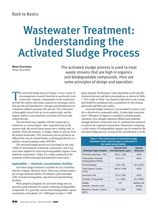
  • 1. 26 www.aiche.org/cep November 2009 CEP Back to Basics The activated sludge process is used to treat waste streams that are high in organics and biodegradable compounds. Here are some principles of design and operation. Mark Sustarsic Tetra Tech NUS Wastewater Treatment: Understanding the Activated Sludge Process T he activated sludge process (Figure 1) uses a mass of microorganisms (usually bacteria) to aerobically treat wastewater. Organic contaminants in the wastewater provide the carbon and energy required to encourage micro- bial growth and reproduction; nitrogen and phosphorous are sometimes added to promote this growth. The wastewater is thoroughly mixed with air in an aeration tank, and the organic matter is converted into microbial cell tissue and carbon dioxide. The microbial mass together with the wastewater is referred to as a mixed liquor. After a specified time in the aeration tank, the mixed liquor passes into a settling tank, or clarifier, where the biomass, or sludge, settles by gravity from the treated wastewater. This continuous process produces an effluent that may be treated further or discharged directly to a publicly owned treatment works (POTW). The activated sludge process was developed in the early 1900s for the treatment of domestic wastewaters, and it has since been adapted for removing biodegradable organics from industrial wastewaters. Today, it is widely employed in the treatment of both municipal and industrial wastewaters. Applicability — chemicals, concentrations, facilities Activated sludge treatment is suitable for use at facilities that have organic chemical waste. These may include munici- pal sewage-treatment plants, oil refineries, pulp and paper mills, food processing plants, and chemical manufacturing facilities. When properly designed, the activated sludge process provides good treatment for wastes containing biodegradable compounds. It is generally used to treat biodegradable organic wastewaters of moderate (10–1,000 ppm) to high (>1,000 ppm) strength. Performance varies depending on the specific chemicals present and their concentrations, as shown in Table 1. The results in Table 1 are based on laboratory-scale testing and should be considered only as guidelines for developing pilot-scale and full-scale studies. Activated sludge treatment is not intended to remove met- als or dissolved or suspended solids. A rather high concentra- tion (>100 ppm) of organics is needed to maintain proper operation. Low-strength industrial effluent and moderate- strength domestic wastewater may be combined for treatment to achieve the required concentration. Wastewater containing a wide variety of biodegradable organics can be treated by the activated sludge process, as long as the concentration is in the Table 1. The performance of activated sludge treatment varies with the type of chemicals in the waste being treated. Chemical Type Treated Typical Feed Concentration, ppm Typical Removal Phenolics (aromatic –OH) 100 to 1,000 >99% Polynuclear Aromatic Hydrocarbons (PAHs) 0.01 to 1 >95% Oil and Grease 10 to 100 40 to 92% Total Organic Carbon (TOC) 500 to 3,000 >90% Ammonia (–N) 10 to 1,000 >95% Cyanide, Thiocyanide 1 to 1,000 40 to 98% Metals (arsenic, mercury, zinc) 0.5 Settles with sludge Benzene, Toluene, Xylene (BTX) 5 to 1,000 >99%
  • 2. CEP November 2009 www.aiche.org/cep 27 hundreds of parts per million. Many remediation sites require the treatment of ground- water, surface water, or landfill leachate with very low organic concentrations, typically less than 10 ppm. This is not high enough to sustain the biological mass needed, and such streams are more appropriately treated by ozone, ultraviolet light, trickling filters, and/or API separators. Some plants combine groundwater, boiler blowdown and stormwater runoff with process wastewater and feed the combined stream to an activated sludge treatment facility. The process Before it enters the aeration basin, raw wastewater (influ- ent) is normally pretreated to remove easily settled solids or other suspended matter, such as oil. Raising the pH will slightly solidify iron and zinc (if present). A steam or air stripper can remove ammonia, phenol, and any light ends, while a filter removes heavy particulates. Because substan- tial changes in the incoming water characteristics will cause a process upset, an equalization tank is sometimes included in the pretreatment system to achieve the required design inlet conditions, such as a certain flowrate or chemical concentration. The pretreated influent is pumped into the aeration tank (or basin), where it is combined with the microorganisms. In order to maintain the bacterial mass in the aeration basin, aerators perform two important functions: they keep the liquid and sludge agitated, and they promote the transfer of oxygen into the wastewater. The aerators run continuously and are strategically positioned to keep the mixed liquor in suspension throughout and avoid the formation of dead zones. Foam gen- erated by the aerators can be contained by anti-foam sprays. The pH of the incoming wastewater or mixed liquor must be steadily controlled for proper microorganism growth. A neutral pH is maintained by adding a caustic or acid, usually 25% by weight in solution. Supplemental nutri- ents in the form of nitrogen (urea) and phosphorus (phos- phoric acid) are added on an as-needed basis, such as when the raw wastewater is an insufficient source of required nutrients. In colder climates, supplemental heat is required to main- tain an acceptable temperature range for the microorganisms. Indirect heat is added to the base of the aeration basin via a steam bayonet or a gas-fired heater. Some plants save energy by first preheating the influent with a hot process stream (e.g., distillation column bottoms) in a heat exchanger. After spending a specified amount of time in the aeration basin, water overflows into a clarifier, where the microbial solids settle by gravity and are separated from the treated water. The clarifier consists of a tank with a center feed well, which promotes even dispersion. The settled sludge is raked from the quiescent zone at the bottom of the clarifier with mechanical scrapers. A portion of the biomass is recycled back to the aeration basin to maintain the desired concen- tration of organisms in the basin. The remaining sludge is pumped from the system, typically by a motor-driven cen- trifugal pump equipped with a flowmeter, for final disposal. Floating materials that collect at the surface of the liquid in the clarifier are collectively referred to as scum. A skimmer constantly moves the scum toward a collection trough that drops it into a receiver for later removal. Both the sludge scraper and the scum skimmer are connected to a common Figure 1. Conventional activated sludge systems process raw influent in the aeration tank before sending it to the clarifier for settling. Oxygen Supply Supplemental Heat (if required)Slude Disposal or Reuse Recycle Sludge Waste Sludge Additional Treatment (Thickening, Dewatering, etc.) (if required) Disposal Final Settling (Clarified) Treated Effluent to: – Additional Treatment (Chlorination, Filtration, etc.) – Disposal (POTW, Surface Water, etc.) – Reuse Raw Influent Pretreatment is Usually Required to Remove Suspended Materials, Oils, etc. by Primary Settling and/or Other Physical Means Surface and/or Deep Impellers Supplemental Nutrient (N, P) Addition (if required) pH Control (if required) Aeration Tank
  • 3. 28 www.aiche.org/cep November 2009 CEP Back to Basics drive shaft powered by a small motor. Clean water travels to the outside edge of the clarifier and is discharged under a baffle and over a notched weir that extends around the periphery. The concentration of total sus- pended solids (TSS) in the effluent discharge is low, 10–100 ppm. This water may go to a POTW, be discharged as surface water in accordance with a National Pollutant Discharge Elimination System (NPDES) permit, or receive tertiary treat- ment such as by activated carbon adsorption. Wasted sludge from the bottom of the clarifier is thick- ened, typically in a vacuum filter press, prior to its ultimate disposal. The degree of wasting determines the solids reten- tion time (SRT) of the system. At a low wasting rate, the SRT would be relatively high — i.e., the solids remain in the system longer. System design Table 2 lists key design parameters that are determined by lab tests and past experiences. The first design methods were formulated based on the retention time of the wastewater in the aeration basin. Gener- ally, short hydraulic retention times (HRT) were chosen for weak (dilute) wastewaters and long HRTs were chosen for strong (concentrated) wastewaters. HRT (measured in days) is defined as the aeration tank volume (V, gal) divided by the discharge rate (Q, gal/d): HRT = V/Q (1) Typical HRTs range from 1–5 d for municipal waste to 1–10 d for industrial waste. Around 1970, other design parameters were developed using fundamental scientific concepts, such as mass balance and microbial growth kinetics. Although design equations ultimately serve as the primary basis for the design of an activated sludge system, pilot plant and/or laboratory tests are essential for developing the design criteria. The resulting design reflects the reaction rates, settling rates, solids reten- tion time, and oxygen requirements for a particular type of wastewater. The rate equations somewhat resemble those used by chemical engineers to describe reactor kinetics, sug- gesting that an aeration tank may be envisioned as a biologi- cal “reactor.” The solids retention time is an important design factor and provides a theoretical indication of how long the microorgan- isms remain in the aeration tank. Since these microorganisms normally reproduce more quickly than they die, some acti- vated sludge must be removed, or blown down, via a recycle line. Blowdown, also called sludge wasting, should be carried out daily to maintain the proper SRT. Without such wasting, the mass of sludge could build up in the settling tank (clari- fier) until solids overflow into the effluent. The SRT (in days) is a function of the aeration tank volume (V, gal), the sludge wasting rate (w, gal/d), and the concentra- tions of suspended solids in the mixed liquor in the aeration tank (MLTSS, g/L) and in the recycle line (MLTSSr, g/L): SRT = (V × MLTSS) / (w × MLTSSr) (2) SRTs for municipal wastewater treatment range from Table 2. Typical characteristics of wastewater can be addressed in the design process by examining these variables. Wastewater Characterization Design Variables Flowrate Hydraulic Retention Rime (HRT) Water Quality Solids Retention Time (SRT) Toxic or Inhibitory Compounds Recycle Ratio (r) Optimization of HRT, SRT and r Oxygen Requirements Bacterial Growth and Decay Factors Sludge Settling Factors Table 3. When upsets occur, follow these suggested guidelines. Problem Probable Cause Remedy Low or high pH in the aeration basin Extremely high or low pH in influent Add alkali or acid to the aeration tank No biological activity Reduce high concentrations of phenols and oils, or add phosphorous or dissolved oxygen to the aeration tank Low dissolved O2 (DO) concentration in the aeration tank Influent feed rate is too high or has slug of organics Reduce feed until DO concentration goes above 1.0 mg/L Concentration of total suspended solids in the mixed liquor (MLTSS) is too high Lower SRT by wasting more sludge High total suspended solids (TSS) concentration in POTW Presence of unwanted bacteria Increase DO or reduce influent organics by reducing feed flowrate Clarifier is overloaded Determine whether the recycle ratio and feed rates are properly set
  • 4. CEP November 2009 www.aiche.org/cep 29 5 to 20 d, whereas SRTs for industrial waste range from 20 to 1,000 d. Another important design factor is the recycle ratio, r: r = q/Q (3) where q is the recycled sludge flowrate (gal/d) and Q is the influent wastewater flowrate (gal/d). Recycle ratios are gener- ally 0.5–3.0 for both municipal and industrial wastewater treatment plants. HRT, SRT and r are interrelated and are the most impor- tant design variables. Combined with sludge settling charac- teristics, they determine the size of the aeration basin, sludge settling tank, and related pumps. The recycle ratio also affects the size of the clarifier. Other important factors that determine the final design include the bacterial growth coefficient (Y) and the decay coefficient (b), each of which may be determined through laboratory treatability testing. The bacterial growth coef- ficient is defined as the mass of bacteria produced per mass of chemical consumed, and it has a value between 0.1 and 0.5. The b coefficient indicates the decay rate of the bacterial organisms. Typical values range between 0.01 and 0.05 d–1. The decay rate does not have as much influence on waste- water treatment system design as the bacterial growth rate. Operating conditions Operation of an activated sludge process relies on maintaining an acceptable environment for microbial activity through routine monitoring and preventive maintenance, and on the ability to survive any process upsets. The following performance considerations may be relevant daily, weekly or monthly. Effluent. Limits on effluent water quality are determined by the state or local environmental agency. The NPDES per- mit generally specifies the allowable discharge flowrate, pH, total organic carbon (TOC, mg/L), and TSS (mg/L). Influent. To ensure smooth operations and avoid upsets, the plant should maintain the influent flowrate, temperature, pH, and concentrations of TOC, TSS, oil and grease, and phenol (which can cause microbial shock) within specified ranges. Values that exceed design limits indicate that pretreat- ment modifications are necessary. For example, excess oil and grease in the incoming water may indicate that the API separator polymer-addition step needs to be modified. Mixed liquor in the aeration tank. The aeration tank must maintain the proper environment for microbial activity. The pH should be between 6.5 and 7.5, the temperature between 15oC and 30oC, the dissolved oxygen (DO) concentration above 2.0 mg/L, and nitrogen and phosphorous at the neces- sary levels. Aeration tanks have pH and DO monitors to auto- matically record these data. The aeration tank should also be routinely checked for mixed liquor volatile suspended solids (MLVSS, mg/L) to ensure that an adequate concentration of organisms is present. Final thoughts It is important to understand that most of the design considerations discussed here are site-specific. This requires the collection of samples from the wastewater to be treated, as well as performing lab analysis and onsite testing to determine the relevant parameters for designing an activated sludge system. MARK SUSTARSIC is a senior process engineer at Tetra Tech NUS (Address: Foster Plaza 7, 661 Andersen Dr., Pittsburgh, PA 15220; Phone: (412) 921-7090; Fax: (412) 921-4040); E-mail: mark.sustarsic@tetratech. com), where he is involved in site investigation, project engineering, detail design, construction supervision, system commissioning and start-up, and customer training. His 33-yr career includes experience with industrial wastewater treatment at steel, chemical, coal-based tar, wood treatment and semiconductor facilities. He holds P.E. licenses in six states and is a member of the National Council of Examiners for Engineering and Surveying (NCEES), as well as Carnegie Mellon’s Pittsburgh Clan and Eastern States Blast Furnace and Coke Oven Asso- ciation. He earned BS degrees in chemistry and chemical engineering from Carnegie Mellon Univ. CEP