
Recomendados
Recomendados
Mais conteúdo relacionado
Mais procurados
Mais procurados (20)
Destaque
Destaque (20)
Semelhante a Image Evaluation: AP Axial C-Spine
Semelhante a Image Evaluation: AP Axial C-Spine (20)
Último
Último (20)
Image Evaluation: AP Axial C-Spine
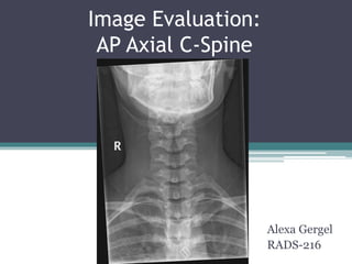
- 1. Image Evaluation: AP Axial C-Spine Alexa Gergel RADS-216
- 2. HIPAA Compliance • This image is HIPAA compliant. • This image does not violate patient confidentiality.
- 3. Marker and Patient ID • A correct post-processed RT anatomical side marker is visible in the image. In addition, a technologist identifier should be included. • The annotated RT side marker is placed correctly in the image.
- 4. Marker and Patient ID • There are no markers superimposing pertinent anatomy. • Additional markers that are necessary for this image include an up or down arrow indicating the position of the patient. This patient was likely supine, and would require a down arrow. This was not used in the original image.
- 5. Marker and Patient ID • The image is displayed correctly based on marker placement.
- 6. Radiation Hygiene • There must be at least three sides of beam restriction on an image. • The beam restriction demonstrated on this image is acceptable because 4 sides of collimation appear to be demonstrated.
- 7. Radiation Hygiene • Beam restriction is the primary source of gonadal shielding. At least 3 sides of beam restriction are necessary, and one of those needs to be on the side closest to the gonads for adequate gonadal shielding. In addition, a gonadal shield must be provided if the gonads are within 5 cm of the primary beam and shielding will not obstruct any anatomy of interest.
- 8. Radiation Hygiene • There is evidence indicating appropriate use of shielding. There is adequate beam restriction on the side closest to the gonads. • In addition, a shield would not obstruct any anatomy of interest, and should be used.
- 9. Routine Positions/Projections • A routine Cervical Spine study will include: AP Axial (15˚ to 20˚ cephalad angulation) (Supine or Erect) Lateral (Right or Left) (Erect or Supine) AP Axial 45˚ Oblique (LPO) AP Axial 45˚ Oblique (RPO)
- 10. Completeness of Position/ Projection • This image does comply with one of the routine positions/projections —the AP axial position/projection. • All anatomical parts are not correctly visualized.
- 11. Artifact Identification • There are preventable physical artifacts visible in the image. • There are body parts that are superimposed that should not be. The mandible is superimposed over the upper cervical vertebra.
- 12. Artifact Identification • Hospital paraphernalia is visible in the image. The patient appears to be wearing a cervical collar which is shown in the image.
- 13. Artifact Identification • Patient clothing/belongings are visible in the image. The patient’s bra is shown at the bottom of the image. • There does not appear to be any indwelling artifacts/foreign bodies visible in the image.
- 14. Artifact Identification • Excess fog is not visible or degrading overall image quality. • There does not appear to be any CR/DR artifacts visible in the image.
- 15. Image Sharpness • “Gross” voluntary motion does not appear to be visible in the image. • Excessive quantum mottle (or image noise) does not appear to be visible in the image. • There does not appear to be evidence of double (or previous/ghosted) exposure visible in the image.
- 16. Image Sharpness • Grid lines, grid artifact, &/or grid cut-off are expected because a reciprocating or stationary grid would likely be used, but do not appear to be visible in the image because a high frequency grid may have been used
- 17. Image Sharpness • Size distortion does not appear to be greater than expected—there is some degree of distortion expected because the object being imaged is three- dimensional. • Shape distortion does not appear to be caused by poor CR/IR/Part Alignment
- 18. Accurate Part Positioning • The part is not completely aligned to the longitudinal axis and the image media. • The part is not accurately centered to the image media. It should be centered at the level of C4. • The CR does not appear to be centered within 1 cm of the anatomical part. C6 c4
- 19. Accurate Part Positioning • The CR does appear to be adequately aligned with the image media. • The CR’s alignment does conform to an accepted IR exposure recognition template/field—4 sides of collimation.
- 20. Accurate Part Positioning Positioning Criteria for AP Axial C-Spine according to Merrill’s Atlas: • Place the patient in the supine or upright position with the back against the IR holder. • Center MSP of patient’s body to the midline of the table or vertical grid device. • Extend the chin enough so that the occlusal plane is perpendicular to the tabletop—preventing superimposition of the mandible and mid-cervical vertebrae. • Center the IR at the level of C4 • Adjust the head so that the MSP is in straight alignment and perpendicular to the IR. • Suspend respiration • CR directed through C4 at an angle of 15 to 20 degrees cephalad • Adjust collimation 10 in. lengthwise an 1 inch beyond the skin shadow on the sides
- 21. Accurate Part Positioning Evaluation Criteria for AP Axial C-Spine according to Merrill’s atlas: • Evidence of proper collimation • Area from superior portion of C3 to T2 and surrounding soft tissue • Shadows of the mandible and occiput superimposed over the atlas and most of the axis • Open intervertebral disk spaces • Spinous processes equidistant to the pedicles and aligned with the midline of the cervical bodies • Mandibular angles and mastoid processes equidistant to the vertebrae
- 22. Accurate Part Positioning • Based on the previous criteria, the anatomical part is not correctly positioned.
- 23. Judicious Exposure Technique • The most radiolucent structure is air within the trachea. This is visible in the image. • The most radiopaque structure in the image is bony cortex of the mandible. This is seen in the image.
- 24. Judicious Exposure Technique • This image demonstrates long-scale contrast (window width). • This image displays adequate brightness (window level) and would likely demonstrate an EI level within normal range.
- 25. Accept/Reject? This image does not meet minimum established standards and should be rejected. • Required corrections for this image: • Include a “down” arrow indicate patient position • The technologist should use their own marker with their ID • Center CR and IR to C4 to include C3 through T2 in the image • Raise mandible if possible in order to demonstrate C3 • If the image only displays up to T2, the bra artifact will not be shown • Align part to longitudinal axis of the IR 123
- 26. References: Frank, E. D., Long, B. W., Smith, B. J., & Merrill, V. (2012). Merrill's atlas of radiographic positioning & procedures. St. Louis, MO: Elsevier/Mosby. McQuillen-Martensen, K. (2011). Radiographic image analysis. St. Louis, MO: Saunders/Elsevier. • http://www.wikiradiography.net/page/Odontoid- lateral+mass+Asymmetry image link • https://hfu- my.sharepoint.com/personal/mness_holyfamily_edu/_layouts/15/onedrive.as px#id=%2Fpersonal%2Fmness%5Fholyfamily%5Fedu%2FDocuments%2FMast er%2FRADS%2D216%20Images%2FMerrills%5FImages%2F8%5FVertebral%5 FColumn%2F8F45%2Ejpg&FolderCTID=0x0120003CB7C277C84FB54094226 CA9570F27D4&AjaxDelta=1&isStartPlt1=1461707900435&parent=%2Fpersona l%2Fmness%5Fholyfamily%5Fedu%2FDocuments%2FMaster%2FRADS%2D21 6%20Images%2FMerrills%5FImages%2F8%5FVertebral%5FColumn
Notas do Editor
- http://www.wikiradiography.net/page/Odontoid-lateral+mass+Asymmetry