
Recomendados
Mais conteúdo relacionado
Mais procurados
Mais procurados (20)
Destaque
Semelhante a cpwd training
Semelhante a cpwd training (20)
Último
Último (20)
cpwd training
- 2. ACKNOWLEDGEMENT It is indeed a great pleasure and privilege to present this report on training at CPWD. I am extremely grateful to my training and placement officer for issuing a Training letter, which made my training possible at CPWD,Durgapur I would like to expressmy gratitude to Er C.P SHARMA for hisinvaluable suggestions, motivation,guidance and support through out the training His methodology to startfrom simple ant then deepen through made me to bring out this projectreportwithoutanxiety. Thanksto all other CPWD officials, operatorsand allother members of CPWD, yetuncounted for their help in completing the projectand see the light of success. I am very thankfulto friends, colleaguesand all other personswho rendered their assistance directly or indirectly to complete this projectwork successfully. I extended my due thanks to Er. S.P SHARMA who gave mevaluabletime and suggestions and guide me a lot at various stages of my Summer Training. AKASH KUMAR
- 3. PREFACE The purpose of preparing the report is to give a detailed description of the site visits that I had done during my summer training in NIT Durgapur Campus under CPWD (Central Public Works Department) from 10/05/2016 to 03/06/2016. This report is an amalgamation of site inspections, interactions with engineers at work site, studies of the important principles of construction including concrete technology, design of concrete structures & important machines involved and finally the conclusions, lessons and ideas which are collected during this brief period of practical experience. The various structural members along with its reinforcement detailing as in the photos is main content along with descriptionof site laboratory and main instruments that was being used in the site.
- 4. ABOUT CPWD CPWD came into existence in July, 1854 when Lord Dalhousie established a central agency for execution of public works and set up Ajmer Provincial Division. It has now grown into a comprehensive construction management department, which provides services from project concept to completion, and maintenance management. It is headed by DG who is also the Principal Technical Advisor to the Governmentof India. The regions and sub-regions are headed by Special DGs and Additional DGs respectively,while the zones in all state capitals (except a few) are headed by Chief Engineers. With country wide presence,the strength of CPWD is its ability to undertake construction of complex projects even in difficult terrains and maintenance in post construction stage.
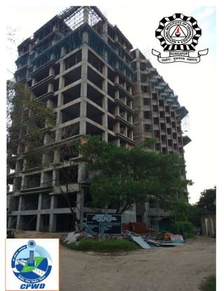
- 5. Presentation on Summer Training held at Construction Site of G+12 Building inside NIT Campus under Central Public Works Department PROJECT REPORT
- 6. WELCOME PRESENTATION SUBMITTED BY:- AKASH KUMAR ROLL NO:-13/CE/26 (CE-4th YEAR) TRAINING PERIOD:-10MAY-03JUNE NATIONAL INSTITUTE OF TECHNOLOGY DURGAPUR GUIDED BY:-Er. C.P. SHARMA EXECUTIVE ENGINEER
- 7. INDEX S.NO DESCRIPTION 1. INTRODUCTION 2. PROJECT OVERVIEW 3. SITE LOCATION 4. SAFETY UNDER CONSTRUCTION SITE 5. FRAMWORK 6. SEQUENCE OF STRUCTURE WORK 7. PROJECT MONITORING 8. QUALITY 9. CONCLUSION
- 8. INTRODUCTION About CPWD:- The Central Public Works Department of India is a Central Government owned authority that is in charge of public sector works in the Country. Central Public Works Department (CPWD) under Ministry of Urban Development is entrusted with construction and maintenance of buildings for most of the Central Government Departments, Public undertakings and autonomous bodies. CPWD, Delhi is the premieragency of Govt. of India engaged in planning, designing, construction and maintenance of Government assets in the field of built environment and infrastructure development. Assets in built environment include Hospitals, Schools, Colleges,Technical Institutes,Buildings, Prisons,Courtsetc.
- 9. GOVERNMENT OF INDIA NIT DURGAPUR PROJECT DIVISION CENTRAL PUBLIC WORKS DEPARTMENT DURGAPUR:- 713209 NAME OF WORK:- Construction of 1250 Boy’s Hostel building AGREEMENT NO. : 06/CE/EE/NITPD/DRG/2013-14 NAME OF CONTRACTOR: NCC LIMITED NAME OF EXECUTIVE ENGINEER:- Er. C.P. SHARMA TENDER AMOUNT:- Rs- 93,92,93,120/ DATE OF COMMENCEMENT:- 07/03/2014 COMPLETION DATE AS PER AGGREMENT:-06/03/2016 ACTUAL DATE OF COMPLETION:- Work is Under Progress (60% work is completed) TIME ALLOWED:- 24 MONTHS
- 10. SITE LOCATION Advantages of this Site Land Store Health Unit Canteen Connectivity of the Yard Ease Of transportation facilities
- 11. Site and Safety Importanceof following safety site rules •Accident rates are higher in Construction sites because people doesn’t pay much attention to the surrounding and the warning signboards that is placed outside of the construction site. Personal ProtectiveEquipment(PPE) Allrefers to protective clothing, helmet, goggles or other garments or equipment designedto protect the bearer’s body from injury Staffs andworkers must wear and use PPE as appropriate • Sub-con and their workers must not wear short pants/slipper to work.
- 12. Sitesafetyrules:- Safety helmets must be worn:- Foot protection should be worn in this area:- •To prevent any injuries on the head as it is the most dangerous part. •Topreventdustparticalsfromthe construction site todraw on the head. •To reduce electrical shock hazard when near exposed electrical conductors which could contact the head. Highvisibility clothing must be worn in this area • So that when to construction work is going on’ it will be easier to be noticed by the bright color of the clothing to prevent any accidents from happening •To preventdangerof footinjuriesdue to fallingorrollingobjectsorobjects piercingthe sole andwhere such employee’sfeetare exposedtoelectrical hazards •No personwhoisunderthe influence of alcohol or drugsare allowedinthe site • as a drunkpersonmay notbe conscious,it maybe dangerous as theycouldwalktobuildings whichare not complete which are full of metal bars therefore it will be dangerous First aid box • Firstaidequipmentis keptinthe site managers office asit iseasierandfaster access incase of emergency Children must not play in the site • When the construction activity is going on, it will be dangerous for the children as any accidents might happen such as getting hit by vehicles or falling object
- 13. Scaffolding platform • Helps to minimize the risk of fall when a worker is doing the construction work high up the building General Safety Rules & Regulation Do’s & don’t: 1. No workmen below 18 years and above 58 years of age shall be engaged for a job. 2. All workmen shall be screened before engaging them on the job. Physical fitness of the person to certain jobs like working at height or other dangerous locations to be ensured before engaging the person on work. The final decision rests with the site management to reject any person on the ground of physical fitness. 3. Smoking is strictly prohibited at workplace. 4. Sub-contractors shallensure adequate supervision at workplace. They shallensure that all persons working under them shall not create any hazards to self or to co-workers. 5. Nobody is allowed to work without wearing safety helmet. Chinstrap of safety helmet shall be always on. 6. No one is allowed to work at or more than two meters height without wearing safety belt and anchoring the lanyard of safety belt to firm support preferably at shoulder level. 7. No one is allowed to enter into workplace and work at site without adequate foot protection. 8. All PPE like shoes, helmet, safety belt etc. shall be arranged before starting the job as per recommendation of PROJECT HSE Head. 9. All excavated pits shall be barricaded and barricade to be maintained till the backfilling is done. 10. Adequate illumination at workplace shall be ensured before starting the job at night. 11. All major, minor accidents and near misses to be reported to PROJECT HSE Head to enable the management to take necessary steps to avoid the recurrence. 12. All scaffoldings / work-platforms shall be strong enough to take the expected load. 13. Adequate firefighting equipment shallbe made availableat workplace and persons are to be trained in firefighting techniques with the co-ordination of safety personnel. Safety googles must be worn. The dust particlesatthe site may be harmful tothe eye therefore bywearinga safetygoogle itcan prevent the dust fromenteringthe eye.Eg flyingparticles, moltenmetals,liquid chemicalsoracids.
- 14. Training for Workers: The following Safety Training topics as minimum shall be covered with all employees and work force prior to starting work assignment. Visitors and vendors will be given a short Safety orientation before being allowed into any construction area. a. Safety Policy b. Personal Protective Equipment c. Emergency evacuation procedure and Alarms d. Fire and Fire Extinguishers e. Scaffold Safety f. Basic Electrical Safety g. Fall Prevention h. Ladder Safety i. Tool Box Talk j. Welding and Gas cutting Safety k. Excavation safety Concreting Safety: • Workers doing concreting work, whether inside excavation or above ground, shall wear proper protective hard hats, Gumboots, PVC gloves etc. Concrete transportations shall be carried out through hand trolleys/Tuff rider (Mini dumper)/Transit Mixer. Cement /aggregate handling employees must use Dust Mask. When transporting concrete in the pan, the person should usespecialtype of hard hat. Use crane /Builder hoist for vertical transportation of the concrete. Train the employee on safe handling of concrete. Concrete pump shall be operate by well-trained operator, Its joint should be tightly braced. The workmen engaged in this operation shall be trained properly. Hot Work Safety (Welding & Gas Cutting): Only trained & experienced personnel shall be authorized for welding & gas cutting work. Gas cylinderstobe keptaway fromopenflamesand othersourcesof heat. Gas cylindersinuse shouldbe mountedontrolleysfor ease of movementforease of movement.
- 15. When torches are being changed or welding stopped for a short time, valves of the cylinders should be kept closed. Work @ Height Safety:- Whenever in doubt contact Site engineer/Project manager Check the stability & Bracing of Scaffolding Keep the planks on scaffolding & tie them with wire Barricade the scaffolding When you are standing on scaffolding or its plank always use Safety Belt When working 2 meters and above HEIGHTS, Safety belt must be worn by employee as well as he has to anchor another end of safety belt to a fixed part which can take his load in case of his fall. FRAMEWORK:- SIGNIFICANCE OF FORMWORK:- 1) Formwork constitutes30% of thecost and 60%of the timein concrete construction. 2) Quality of concretefinish and soundness of concretedepends verymuch on the formwork system. 3) Desired shapeof concreteis notpossible if formwork notdoneproperly. 4) Formwork should be properlydesigned, fabricatedanderectedtoreceive concrete. 5) Accidents happen because of thefaultyformwork and scaffoldingor staging. SAFETY IN USING FORMWORK:- Components arelightin weight formanual handling. Loose or hanging components areminimal. Appropriateuseof tools. Minimum operationsareinvolved in each reuse. Trained & experienced safflowers shall only do erection, dismantling and modification of scaffold as per approved designed. Scaffold should be made of sound materials & adequate strength to support the weight for the work load on it and that it is securely anchored and stable. Sufficient sills or under pinning shall be provided for all scaffolds erected on filled or ground.
- 16. Before making use scaffold shall be ensured whether it is safe for the purpose or not by providing tags (Green for Safe and Red with cross mark to unsafe). Check scaffolds periodically and especially after rains and storm to ensure that locking pins are intact, all nuts-bolts are tightened, footing intact and that there is no scouring below the footing. A daily visual check will also be carried out by the supervisor to remove defects, if any. If any defect / unsafe is noticed, the proper warning (‘NOT SAFE FOR USE’) in local language shall be displayed at the start of access to the scaffold with Red Cross mark. PLANT AND MACHINERIES The plants and machineries to be used at the site are either owned by the company or hired. They have different fuel and power consumption and different output. So, the planning section is responsible in maintaining these records. They are enlisted below – Serial no. Machineries Companyname Capacity 1 Backhoe loader JCB .25 m3 2 Transitmixer TATA,AshokLeyland 6 m3 3 Bar cuttingmachine JAYMAC,JAYPEE - 4 Bar bendingmachine JAYMAC,JAYPEE - 5 Concrete pump SchwingStetter 30 m3 /hr 6 Hydra ACE 11 ton 7 Builderhoist PRIMAX 1000 kg 8 Passengerhoist KANGBO 1500 kg 9 Rope suspendedplatform JAYPEE 800 kg 10 Towercrane JIANGLU 10 ton 11 Multifunctionalhoist SPARTAN 1500 kg
- 17. Bar bending & Bar cutting Machine: This type of machine is used for bending and cutting of bars. This machine is powered by electric motor. Hydra:- It carries load from one place to another place. Its capacity is 11 ton. Concrete pump:- A concrete pump isused for transferringconcrete bypumpingthrough pipelineto reachitto the properplace. Tower Crane: A crane isa type of machine that can be usedforbothto lift and lowermaterial and to move themhorizontally. It’smainlyusedforlifting heavythingsand transportingthemtoother places. Builder hoist: A hoistis a device usedforliftingor loweringaloadbymeansof a drum or lift-wheel around whichrope or chainwraps. It maybe manually operated,electricallyor pneumaticallydrivenand may use chain,fiberorwire ropesas itsliftingmedium. The load isattachedto the hoistbymeansof a lifting hook. Transit mixer: It ismade to transportand mix concrete upto the constructionsite.They can be charged withdrymaterialsandwater, withthe mixingoccurringduringthe transportation.The concrete mixing transport truck maintainsthe materials’liquiditystate throughagitationor turningof the drum,unit delivery. Hydraulic pump: These are verycommonpumpsas we are familiarwithitindayto day work. Generallyitis usedto sprinklingwaterincuringof concrete work. Generallyithasa capacity of 1HP.
- 18. Generator: Itisan electrical instrumentusedforgeneratingpoweranditbringsother machineries inthe planttoworkwhile there isinsufficiencyof electricity. Winches: Wincheshelpsinvertical movementof anymachine.e.g.fordrivingpiles, raising& loweringhoistsorothermaterials. Backhoe loader:-Backhoe-loader is engineering vehicle, which consist of a tractor, fitted with a shovel or bucket on the front and a small backhoe on the back. Uses:- Digging shallow excavations Digging trenches General grading Lifting loads Loading and carrying materials FINENESS MODULUS OF FINE AGGREGATE OBJECT: To determinethe finenessmodulusof aggregate. THEORY: Sieve analysishelpstofindparticle size distributionof fine aggregates IS SPECIFICATIONS: As pertable 4 of IS 383-1970 IS SIEVE GRADING GRADING GRADING GRADING DESIGNATION ZONE I ZONE II ZONE III ZONE IV 10 mm 100 100 100 100 4.75 mm 90-100 90-100 90-100 95-100 2.36 mm 60-95 75-100 85-100 95-100 1.18 mm 30-70 55-90 75-100 90-100 .600 mm 15-34 35-59 60-79 80-100 .300 mm 5-20 8-30 12-40 15-50 .150 mm 0-10 0-10 0-10 0-15
- 19. PROCEDURE: The testsample ovendriedattemp.100 0 C →Arrange the sieve as10mm,4.75 mm,2.36 mm,1.18 mm,600 micron,300 micron,150 micron,75 micron&Pan→1000 gm. sample takenand sieved→Take weightretrainedingm.fromeachindividualsieve→Calculationdescribe below: The followinglimitsare taken as guidelines:- Fine Sand : FinenessModulus : 2.2-2.6 MediumSand : FinenessModulus : 2.6-2.9 Coarse Sand : FinenessModulus : 2.9-3.2 EXPWRIMENTA DATA :- SIEVE SIZE WEIGHT % WEIGHT CUMULATIVE % CUMULATIVE % (mm) RETAINED(gm.) RETAINED RETAINED PASSING 10 0 0 0 100 4.75 4 0.4 0.4 99.6 2.36 18 1.8 2.2 97.8 1.18 157 15.7 17.9 82.1 .600 137 13.7 31.6 68.4 .300 280 28 59.6 40.4 .150 348 34.8 94.4 5.6 .075 53 5.3 99.7 0.3 PAN Calculation:- Summationof cumulative % retained =∑ (0.4+2.2+17.9+31.6+59.6+94.4) =206.1 Fineness Modulus= 206.1/100=2.06
- 20. TESTS FOR CEMENT: a) Standard Consistency of cement by Vicat’s Apparatus: Thisis a testto estimate the quantity of mixingwater tofromapaste of normal consistencydefinedasthatpercentage water requirementof the cementpaste,the viscosityof whichwill be suchthatthe Vicat’splunger penetratesuptoa point5 to 7 mmfrom the bottomof the Vicat’smould.The waterrequirement for varioustestsof cementdependsonthe normal consistencyof the cement. OBJECTIVE: To determinethe amountof wateraddedtothe cementto forma cementpaste. APPARATUS USED: The mainapparatususedinthisexperimentis Vicat’sApparatus. It consistof a non-porous plateandaneedle of diameter10mmwhichwill penetrateonthe mould. CEMENTSPECIFICATION Brand name: ULTRATECH CEMENT Type of cement: Portland pozolana cement Temperature: 32°C Humidity: 75% RESULT SHEET SERIAL WEIGHT OF % OF WEIGHT OF PENETRATION STANDARD NO CEMENT WATER WATER READING FROM CONSISTENCY TAKEN(gm) ADDED ADDED(gm) BOTTOMOF VALUE MOULD(mm) 1 300 30% 90gm 35mm 2 300 33% 99gm 26mm 37 3 300 36% 108gm 12mm 4 300 37% 111gm 7mm Therefore,the standardconsistencyof cementis 37%.
- 21. b) Initial and Final setting time: These testsshall be conductedata temperature of 27±2°c and65+5% of relative humidityof the laboratory.A paste of 300 gm. of cementispreparedwith0.85 timesthe waterrequiredtogive a paste of standardconsistency.The Vicat’smouldisfilledwiththesepaste makingitlevel withthe top of the mouldand slightlyshake toexpelair. Setting time of cement: When water is added to cement, the resulting paste starts to stiffen and gain Strength and lose the consistency simultaneously. The term setting implies Solidification of the plastic cement paste. Initial and final setting times may be regardedas the two stiffening states of cement. At the beginning of solidification, called the initial set, marks the point in time when has become unworkable. Initial setting time may be defined as the time taken by the paste to stiffen to such an extent that the Vicat’sneedle is not permitted to move down through the paste to within 5±0.5mm measured from the bottom of the mould. The final setting time is the point at which the set cement has acquired a sufficient firmness to resist a certain defined pressure. In the experiment it is determined as the time elapsed between the time of adding water to the cement to the time when the ring fails to make any impression on the mould surface. Most specifications require an initial minimum setting time at ordinary temperatures of about 30 minutes and a final setting time not more than 600 minutes. Observation value: Weight of sample taken: 300gm %of calculated water: (0.85 ×37) = 31.45% Water added to cement on 94.5gm Initial settingtime:81 min Final settingtime:190 min c) FINENESS OF CEMENT: Finenesswaslongcontrolledbysievetests,butmore sophisticatedmethodsare now largelyused. The most commonlymethodusedbothforcontrol of the grindingprocessandfor testingthe finishedcement, measuresatthe surface perunitweightof the cementbya determinationof the rate of passage of airthrougha bedof the cement.The degree of finenessof cementisthe measure of the meansize of the grains init.The sieve method-90micronsieve isused. RESULT: Sample taken: 100gm Retained on 90 micron sieve : 6gm Passing through 90 micron sieve: 94gm Therefore,finenessof cementis 6%.
- 22. compressive StrengthTest of Concrete: Cement,fine aggregate andcoarse aggregate (upto38mm) tobe usedfor makingconcrete are broughtto fromtemperature (preferably27±3°C) before commencingthe test.The ingredientsare weighedinthe ratiotobe usedinthe fieldandare mixedbyhandmixingorby machine mixing. First,the cementandmixedtill these are distributeduniformcolourisachieved.The coarse aggregate are thenaddedand mixedtill theseare distributedthroughoutthe mix.The wateristhen addedand the entire batchmixeduntil the concrete appearstobe homogeneousandhasthe desired. The test specimens recommended are 150mm × 150mm × 150 mm cubes. The mixed concrete is filled into the mould in layers of 50mm to achieve full compaction. Each layer of mix so placed is tamped with bar, 16mm in diameter and 600mm long, 35 times. The test specimen are stored at a temperature of 27±2°C and at 90% humidity for 24 ± 1⁄2 hour from the time of addition of water to the dry ingredients. After this period the specimens are removed from the mould and placed in water and kept there until taken out just prior to test. Normally the recognized age of test of specimens is 7 and 28 days. The specimen is placed between the platens of the compression testing machine with the care that the axis of specimen is aligned with the centre of thrust of the spherically seated platen. The applying load procedure is same as for brick test )Example:- Grade of concrete: M40 Date of casting : 29/4/16 Date of testing : 27/5/16 Applied load : 1060 KN After 28 days, the compressive strength of cube=(applied load on the cube / cube surface area) =1060*103 N /150*150 mm2 = 47.1 Mpa COMPRESSION TESTINGMACHINE
- 23. BEAMS Beams are flexural elements which carry the load from the slabs to transfer it to the columns. The beams were designed using LSM (Limit State Method) for 25 combinations 1. 1.5 (DL + IL) 2. 1.2 (DL + IL + EXTP) 3. 1.2 (DL + IL + EXTN) 4. 1.2 (DL + IL – EXTP) 5. 1.2 (DL + IL – EXTN) 6. 1.2 (DL + IL + EZTP) 7. 1.2 (DL + IL + EZTN) 8. 1.2 (DL + IL – EZTP) 9. 1.2 (DL + IL – EZTN) 10.1.5 (DL + EXTP) 11.1.5 (DL – EXTP) 12.1.5 (DL – EXTN) 13.1.5 (DL + EZTP) 14.1.5 (DL + EZTN) 15.1.5 (DL – EZTP) 16.1.5 (DL – EZTN) DL Downwards IL (Imposed/Live load) Downwards EXTP (+Torsion) +X; Clockwise torsion due to EQ EXTN (-Torsion) +X; Anti-Clockwise torsion due to EQ EQ EZTP (+Torsion) +Z; Clockwise torsion due to EQ EZTN (-Torsion) +Z; Anti-Clockwise torsion due to EQ EXTP: EQ load in X direction with torsion positive EXTN: EQ load in X direction with torsion negative EZTP: EQ load in Z direction with torsion positive EZTN: EQ load in Z direction with torsion negative Based on the above combinations moment envelope for a particular beam is developed. Reinforcements are calculated and then maximum reinforcement out of all the cases is being used. In the design process of a beam, first we determine the main tensile bars required to resist the bending moment. Out of these bars, we bent one or two to resist shear near the supports. The bars at the bottom corners are not bent. They remain 'straight', and are extended from support to support to anchor the stirrups properly. It can also be seen that beyond the bottom point of bent, the bent- up bar is no longer available at the tension zone of the beam. In general, this does not cause a problem because nearer the supports, the Bending moment (sagging type) is of a lesser magnitude, and so all the bars will not be required there. However in every design process, it is important to ensure that the bent-up bars are no longer required beyond the point of the bent, and that development length requirements are satisfied.
- 24. We have to consider another point while using bent-up bars for shear reinforcement. That is., the design should not be in such a way that all the design load due to shear is resisted by the bent-up bars. We must provide stirrups also. Cl.40.4 of the code specifies that “Where bent-up bars are provided, their contribution towards shear resistance shall not be more than half that of the total shear reinforcement.” Few notable points that need to be essentially checked in beam reinforcements are: - The length of the hooks in case of stirrups should be 10d (d=diameter of bar). This is as per Special Publications (SP 34). The hooks must be left in the compression zone otherwise initiation of cracks due to stress concentrations may take place. Proper provision of clear cover must be done using small concrete/stone pieces. For cantilever beams tension reinforcements are often placed at the bottom (a common mistake due to carelessness of the workers). Adequate transverse bars needs to be provided in case the longitudinal bars of the beam are parallel to the main reinforcements in the adjacent one way slab. This is done to ensure the integral action of the beam and slab. Hooks of alternate stirrups on opposite sides is the correct method of placing stirrups. COLUMNS Columns are the compression members often accompanied by moments about one or both axes. The column is designed for resisting the compression and moments. In case of the hostel building the columns are designed as short columns as effective length to least dimension ratio is less than 12 in all cases & hence does not requires to be designed for buckling as well. (Refer to clause 25.1.2 of IS 456:2000) The column section shall be designed just above and just below the beam column joint and larger of the two reinforcements shall be adopted. This is similar to what is done for design of continuous beam reinforcements at the support. The end moments and end shears are available from computer analysis. All columns are subjected to biaxial moments and biaxial shears. The longitudinal reinforcements are designed for axial force and biaxial moment as per IS: 456. Since the analysis is carried out considering centre-line dimensions, it is necessary to calculate the moments at the top or at the bottom faces of the beam intersecting the column for economy.
- 25. Detailing: Detailing of reinforcement as obtained is discussed in SP 34. The reinforcement area obtained above at various column-floor joints for lower and upper column length. The area required at the beam-column joint shall have the larger of the two values, viz., for upper length and lower length. Since laps can be provided only in the central half of the column, the column length for the purpose of detailing will be from the Centre of the lower column to the Centre of the upper column. This length will be known by the designation of the lower column. It may be noted that analysis results may be such that the column may require larger amounts of reinforcement in an upper storey as compared to the lower storey. This may appear odd but should be acceptable. Few notable points that must be remembered in checking the column reinforcements are:- Adequate lapping or splicing must be provided to maintain a strong tie between continued and discontinued bars conforming to clause 26.2.5 of IS 456:2000. Sometimes casting work is done overlooking the non availability of adequate lapping length of a particular longitudinal bar. Adequate transverse reinforcements must be provided in the columns to effectively hold the concrete in its position and prevent premature buckling.(Refer clause 26.5.3.2 of IS 456:2000) Column reinforcement at the site
- 26. SLABS Slabs are plates which are designed based on the Imposed load and dead loads coming on the slab by its intended users in this case the hostel boarders. All the slab panels are designed as two way slabs except the corridors which are designed as one way slabs. Table 26 of IS 456:2000 gives us the moment coefficients based on different edge conditions, which are used to calculate the moments and hence for design of slabs. Few important points during slab construction are:- Main reinforcement should always be along the shorter side which is a common mistake done. Cantilever portions should be definitely checked for proper placement of reinforcements i.e. the tension reinforcements should be above unlike that of other slab panels. Proper clear cover must be maintained using concrete blocks/stone. Cranking of rods at 0.15l from the face of the support(l=effective span of the slab in that direction) must be done in order to take account of the hogging bending moment arising due to partial fixity at the supports. STAIRCASES A stair is a series of steps, each elevated a measured distance, leading from one level of a structure to another. When the series is a continuous section without breaks formed by landings or other constructions, the terms flight of stairs or run of stairs are often used. Other terms that can be properly used include stairway and staircase. For a period of time, the popularity of the one-story structure in residential construction minimized the frequency of stair construction. Framing carpenters could usually handle the relatively simple task of constructing the service stairs leading from the first floor to the basement level. However, revival of traditional two story styles along with split-level and multilevel designs has again made fine stair construction an important skill. However, in new construction, public rooms are usually on the first floor. Due to this, there is a trend to move the stairs to a less conspicuous location. Stair construction requires a high degree of skill. The quality of the work should compare with that found in one cabinetwork. The parts for main Electrical connections at the slab
- 27. stairways are usually made in millwork. The Live loads acting on the stairs can also be obtained from the data books or relevant codes. IS 875: 1987(part II) recommends a uniformly distributed load of 5kN/m2. This load is to be applied on both the sloping portion and the horizontal landing. In buildings such as residences, where the specified Live loads on the floors do not exceed 2kN/m2, and the stairs are not liable to be overcrowded, the Live load can be taken as 3kN/m2. As in the case of self wt. of finishes, the LL obtained from data books or codes, is assumed to act vertically on a horizontal plane, and so there is no need make any modifications, and we can apply it directly. Dead Load is to be considered as per the dimensions of the staircases. The horizontal portion of the stair is called the Landing. The horizontal distance between the first and last risers is called the Going. In the above elevation and plan views, we can see that the step near the intermediate landing is contributing towards making up the area of the Landing. This situation can be seen at the top most landing also. At the intermediate landing, the two flights are connected together. But as we will soon see in the ‘design of reinforcements for the stairs’, the main bars of the two flights are not connected together. Only the distributor bars in the intermediate landing will be common to the two flights. So there is no transfer of force between the two flights. In other words, the loads and forces in one flight will not have any effect on the other flight. One important point about stairs is placing of chairs at appropriate place to maintain the effective depth between upper and lower layers of reinforcements. The picture shows the chairs & its positioning. In caseof stairs even at the supportregion i.e. at the landings negative reinforcement are to be provided in order to take into account of the hogging moments arising out of partial fixity of the support.
- 28. SITE EXECUTION 1. Formwork: Purpose of Formwork: Shuttering or formwork is the temporary arrangement by wood/steel/plyto hold concrete in required shape and size up to certain period for gaining adequate strength of the concrete. Materials used: Steel plate and channel Plywood (film coated 12mm thick) Soft pine Runner Hard Wood Runner MS Wailer MS Channel Vertical adjustable prop or CT prop (3m) Cup lock System 2.Formwork for Slab Casting: Apparatus Used: Hammer Crow-bar Crane LevelingInstrument Plumbbob MeasuringTape RightAngle Rope Plywood (film coated 12mm thick) Soft pine Runner Hard Wood Runner MS Wailer MS Channel Vertical adjustable prop or CTprop (3m) Tie rod (16mmØ) Cup lock System H-frame Clamps Ring nut Base plate Sole plate Nail Binding wire
- 29. 3.Reinforcement Work: Purpose of Reinforcement Work: The purpose of placing of reinforcement is to provide tensile capacity to cement concrete which itself has very low tensile strength but sound compressive strength. Apparatus used: Hammer Chisel Bar bending machine Bar cutting machine Dice for local bending 4. Concreting: Purpose of Concreting: Concretingisthe mostimportantoperational partof a projecthaving structuresmade of ReinforcementCementConcrete.Itprovidescompressive strengthtothe membersof the RCC structures. Apparatus Used: Batching Plant Mechanical Mixer with Weigh Batcher Transit mixer Concrete Pump Air Compressor Vibrator Wooden Hammer/Leveler Spade Shovel Trowel Curing job:- Cementgainsstrengthandhardnessbecause of the chemical actionbetweencementand water.Thischemical reactionrequires moisture favourable temperature andtime referred to as the curing period.Curingof freshlyplacedconcrete isveryimportantforoptimum strengthanddurability.Curingof anyconstructionmemberisdone foratleast7 days.For slaband beams,bondingisrequired,butforcolumns,moistgunnybagsare usedforcuring.
- 30. 6. Brickwork: Purpose of Brickwork: Brickworks are of two types, load bearing and non-load bearing. Non-load bearing brickworks, generally done in the frame structure construction arefor providing privacy and protection from weathering. Apparatus used: Shovel Mixture Machine Iron Pan Trowel Plumb bob Spirit level Wooden ruler for pointing Broom Platform 7. Plastering:- Purpose of Plastering: The purpose of plasteringoverConcrete orBrickisto provide asmoother surface on which colourorany othersurface treatmentcouldbe done. Apparatus Used:- Mixture machine ,Shovel, Iron pan, Trowel, Spirit level, Plumb bob, Broom, Platform, Staging props, clamps, etc. Makesuretowetthesurfaceatwhichyou areapplying plaster. Thiswill ensurebetterstickingof theplaster. Don’tusedrycementover theplasticsurface,asthereischancesof itgetting distorted. Usetheappropriate amountof waterwhilemixing chemicalsor else, therearechancesthatitwon’t set uptothebrickwall. Wait for 24 hoursafterplasteringthewalland splatter water overitforthenext3-4days.The splattered waterwillensure bettersetupof theplaster. 8. Waterproofing: Purposeof Waterproofing: The purpose of waterproofingistomake any surface of a structure impervious towaterormoisture. Apparatus used: Mixture Machine o Shovel o Iron pan o Plumb Bob o Wooden Plainer or channel
- 31. 8. Shuttering: 12mm thick plywood is used with a section of (2440 mm×1220mm) size. Sometimes steel plate of (600mm×1200mm)is also used instead off ply-board. Shuttering members should be strong enough to withstand the ideal load of the poured concrete until the concrete gets hardened. SupportingMembers: Vertical propsorcup-lockmembersare usedtosupportthe formworkfor beamsandslabs. The formworkforbeamis constructedfirstandthentheyare fittedat an exactlevel byextendingthe propsup to thislevel.Cup-lockisusedtoattachthe horizontal brace tothe vertical supportto preventthe undesirable horizontalmovementof the vertical props.Eachsupportingmemberhasa maximumlengthof 3.5m.Wheneverthis3.5mheightof vertical membersappearstobe insufficient to reach to the soffitlevel of the slaborbeam, some adjustable propsare used.Adjustable propisa kindof vertical supportingmemberinwhichone canadjustthe heightas required.Incase of columns,vertical shutteringmembersare usedwithsupportingwoodenmembers.Woodenbattens of(75mm×50mm) size are attachedto the plywoodtopreventbulgingof the formworkunderthe loadof placedconcrete inside the formwork.There are primaryandsecondarysupportingmembers for columnformworksandbothare essential tomake the formworkstrongenough. Grade of Concrete tobe usedin construction: MEMBER/STRUCTURE GRADE Column and beam column junction M40 Beam M25 Slab M25 Basement M25 Pile M25
- 32. Cover providedto Reinforcement: MEMBER/STRUCTURE CLEAR COVER Beams 20 mm Columns 40 mm Floors/roof slab 20 mm Wall 25 mm Pile 50 mm SECTION OF COLUMNS SHUTTERING OF COLUMN POURING CONCRETE INTO COLUMN
- 33. PROJECT MONITORING PROJECT MONITORING SYSTEM The followingthreereportsaremade forthetracking- Monthlyprogress report Jobcost report Project performancereport Quality Quality Control System of CPWD Field Level Circle Level Core Wing at Directorate Level QualityAssuranceUnits In The Region Contract & Manual Standards and Specifications Quality Assurance Techno-Legalmatters Technology Application & Standards units. CONCLUSION It was awonderful learning experienceatCPWDoffice. I gaineda lotof insight regarding FINISHING aspects of Construction site. I wasgivenexposurein almostall thedepartmentsatthe site, butI had liked tohighlighttheareasof safety, quality management, material management and execution.