Truss examples
•Transferir como DOCX, PDF•
26 gostaram•46,782 visualizações

1) The documents provide examples of solving for forces in truss members by using free body diagrams and equilibrium equations. 2) The solutions involve drawing FBDs of the trusses or sections of trusses, then writing the ΣF and ΣM equations and solving the systems of equations. 3) The determined forces are then identified as either tension or compression forces in the members.

Recomendados
Mais conteúdo relacionado
Mais procurados
Mais procurados (20)
Destaque
Destaque (20)
Semelhante a Truss examples
Semelhante a Truss examples (20)
Mais de AHMED SABER
Mais de AHMED SABER (20)
Truss examples
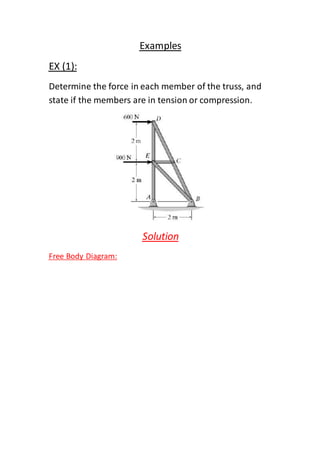
- 1. Examples EX (1): Determine the force in each member of the truss, and state if the members are in tension or compression. Solution Free Body Diagram:
- 2. First, we should calculate reactions at A and B: =0AM∑ ) (2) + (900) (2) + (600) (4) = 0y(B 2100 N = 2100N-=y. B. . =0yF∑ y= By= 0 AyB-yA 2100N = 2100 N-=yA = 0xF∑ (1)----------1500-=xB–x+ 900+ 600 = 0 AxB–xA Node A:
- 3. = 0xA = 2100 N (Tension)1F By substituting in eqn 1, we get: =1500 NxB Node D: 1341.6 N-=6+ 600 = 0 F6F 𝟏 √𝟓 = 1341.6 N ( compression )6F (1341.6) = 0 𝟐 √𝟓 -2F (Tension)= 1200 N2F Node c: (compression)= 1341.6 N5= F6Fand= 03FCE is a zero force member,so Node E:
- 4. 900-sin45 =4F 1272.8 N = 1272.8 (compression)-=4F EX(2): The truss, used to support a balcony, is subjected to the loading shown. Approximate each joint as a pin and determine the force in each member. State whether the members are in tension or .2 KN=2KN, P3=1Pcompression. Set Solution Diagram:Free Body
- 5. =0CM∑ = 8 KNx(1) = 0 ExE-2(1) + 3(2) = 0xF∑ x= Ex= 0 CxE-xC = 8 KNxC = 0yF∑ (1)---------= 5y+ Ey3 = 0 C–2-y+ EyC Node E: = 0yE )compression= 8 KN (1F8-=1F By substituting in eqn 1, we get:
- 6. = 5 KNyC Node C: = 7.07 KN ( Tension )√ 𝟐= 52Fsin45 = 52F = 83cos45 + F√ 𝟐= 8 53cos45 + F2F = 3 KN (Tension)3F Node B: = 3 KN (Tension)5F = 2 KN (Tension)4F Node A:
- 7. = 0yF∑ sin45 = 063 + F = 4.24 KN (Tension)√ 𝟐= 36F EX(3): Determine the force in each member of the truss and state if the and= 2 KN1Pmembers are in tension or compression. Set = 1.5 KN.2P Solution m:Free Body Diagra
- 8. =0AM∑ ) = 0√ 𝟑(2x(1.5) (6)+(2) (3) + E 4.33 KN = 4.33 KN-=xE = 0xF∑ = 4.33 KNx4.33) = 0 A-+ (xA = 0yF∑ = 3.5 ……………..(1)y+ EyA Node C: = 3 KN (Tension)2Fsin30 = 1.52F
- 9. 2.6 KN=2.6 KN (compression)-=√ 𝟑1.5-=1F+ 3cos30 = 01F Node D: = 2 KN (Tension)3F 2.6 KN =2.6 KN (compression)-=4F Node E: 2.6 = 0-cos30 + 4.335F 2 KN = 2 KN (compression)-=5F = 1 KNy2) sin30 = 0 E-+ (yE By substituting in eqn(1), we get = 2.5 KNy+ 1 = 3.5 AyA Node A:
- 10. cos60 = 2.56F = 5 KN (Tension)6F EX(4): Determine the force in each member of the truss and state if the = 0.2PandKN4=1Pmembers are in tension or compression. Set Solution Free Body Diagram:
- 11. =0AM∑ = 2 KNy(4) (2) = 0 E–(4)yE = 0yF∑ 2 KN = 2 KN-=y+ 2 = 0 AyA = 0xF∑ (1)---------x= Ax= 0 ExA-xE FD & BG are zero force members, so and as a result= 02Fand= 09F AG & GC & FC & FE became zero force members,so = 08= F10= F3= F1F Node A:
- 12. = 24(0.75/1.25)F = 10/3 = 3.33 KN (Tension)4F = 8/3 = 2.67 KN4= (1/1.25) FxA By substituting in eqn (1), we get = 2.67 KNxE Node B: = 3.33 KN (Tension)5= F4F Node F: = 27(0.75/1.25) F = 10/3 =3.33 KN (Tension)7F Node D:
- 13. = 3.33 KN (Tension)6= F7F EX(5): Determine the force in each member of the truss and state if the andN1200=1Pmembers are in tension or compression. Set = 1500 N.2P Solution Free Body Diagram: =0cM∑ 500(3.6) =0–x1.5 B
- 14. = 1200 NxB =0xF∑ +1200 +1200 =0xC 2400 N-=xC =0yF∑ = 500 Ny500 = 0 C–yC Node D: 1300 N = 1300 N (compression)-=2F500-=2(1.5/3.9)F = 2400 N (Tension)1F= 12002+ (3.6/3.9)F1F AB & AC are zero force members, so = 05= F3F Node B: 500 N = 500 N (compression)-=4F EX(6):
- 15. Determine the force in each member of the truss and state if the members are in tension or compression. Solution Free Body Diagram: =0cM∑ (2.4) = 0yA-3(1.2) + 4.5(3.6) = 8.25 KNyA = 0x=0 CxF∑ =0yF∑ = 0.75 KNy= 0 C-4.5–3–+ 8.25yC BD and EA are zero force members, so
- 16. = 08= F3F Node C: = 1.25 KN (Tension)4F= 0.754(0.9/1.5)F +(1.2/1.5) (1.25) = 01F 1 KN = 1 KN (compression)-=1F Node B: = 1 KN (compression)2= F1F Node D: + 0.75 + 3 = 05(0.9/1.5)F 6.25 KN = 6.25 KN (compression)-=5F 5 = 0–6F–1
- 17. 4 KN = 4KN (compression)-=6F Node E: = 4 KN (compression)7= F6F Node F: = 4.59(0.9/1.5) F = 7.5 KN (Tension)9F EX(7): Determine the force in members GE, GC, and BC of the truss. Indicate whether the members are in tension or compression. Solution •Choose sectiona-a since it cuts through the three members
- 18. •Draw FBD of the entire truss = 400Nx= 0 AxA-= 0; 400Nx∑F+ = 900Ny(12) = 0 Dy400(3) + D-1200(8)-= 0;A∑M = 300Ny1200 + 900 =0 A–y= 0; Ay+ ∑F • Draw Free Body Diagram for the sectionportion ∑MG = 0; - 300(4) – 400(3) + FBC(3) = 0 FBC = 800N (Tension) ∑MC = 0; - 300(8) + FGE(3) = 0 FGE = 800N (Compression) + ∑Fy = 0; 300 - 3 5 FGC = 0 FGC = 500N (Tension) EX(8):
- 19. Determine the force CF of the truss shown in the figure. Indicate whether the member is in tension or compression. Assume each memberis pin connected. Solution Free Body Diagram: Section aa will be used since this section will “expose”the internal force in member CF as “external”· on the free-body diagram of either the right or left portion of the truss. It is first necessary, however, to determine the supportreactions on either the left or right side. The free-body diagram of the right portion of the truss, which is the easiest to analyze, is shown in the following figure:
- 20. Equations of Equilibrium: We will apply the moment equation about point 0 in order to eliminate the two unknowns F FG and FcD. The location of point 0 measured from E can be determined from proportional triangles. i.e. 4/(4 + x) = 6/(8 + x ) . x = 4 m. Or, stated in another manner. The slope of member GF has a drop of 2 m to a horizontal distance of 4 m. Since FD is4 m. Fig. then from D t0 O the distance must be 8 m. An easy way to determine the moment of FCF about point O is to use the principle of transmissibility and slide FCF to point C. and then resolve FCF into its two rectangular components. We have = 0;O∑M+ 4.5(4) = 0–sin45 (12) + 3(8)CFF- (compression)= 0.589 KNCFF EX(9):
- 21. Determine the force in member EB of the roof truss shown in the figure. Indicate whether the member is in tension or compression. Solution