

Recomendados
Recomendados
Mais conteúdo relacionado
Mais procurados
Mais procurados (20)
Destaque
Semelhante a Design
Semelhante a Design (20)
Último
Último (20)
Design
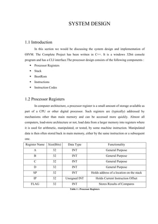
- 1. SYSTEM DESIGN 1.1 Introduction In this section we would be discussing the system design and implementation of OIVM. The Complete Project has been written in C++. It is a windows 32bit console program and has a CLI interface.The processor design consists of the following components : Processor Registers Stack BootRom Instructions Instruction Codes 1.2 Processor Registers In computer architecture, a processor register is a small amount of storage available as part of a CPU or other digital processor. Such registers are (typically) addressed by mechanisms other than main memory and can be accessed more quickly. Almost all computers, load-store architecture or not, load data from a larger memory into registers where it is used for arithmetic, manipulated, or tested, by some machine instruction. Manipulated data is then often stored back in main memory, either by the same instruction or a subsequent one. Register Name Size(Bits) Data Type Functionality A 32 INT General Purpose B 32 INT General Purpose C 32 INT General Purpose D 32 INT General Purpose SP 32 INT Holds address of a location on the stack IP 32 Unsigned INT Holds Current Instruction Offset FLAG 32 INT Stores Results of Compares Table 1 : Processor Registers
- 2. 1.2.1 General Purpose Registers Registers A, B, C, and D are general purpose registers that is we use as variables in the architecture and any value to be manipulated in the program gets stored in the register and is then manipulated. Each of these is 32 bit in length. They are however declared as int in the source file written in C. 1.2.2 Stack Pointer Stack which is a continuous memory segment is required for various functionalities which would be discussing shortly. However, the stack requires a pointer which can hold the address of a memory location on the stack so that when ever anything is to be pushed or moved from/to the stack this pointer can be used. This is facilitated by the SP register. In our architecture. This register is 32bits long and is declared as an int in the source file. Whenever something is pushed on the stack. The stack pointer is incremented and whenever something is popped it is decremented. 1.2.3 Instruction Pointer The IP is the program counter for the bootrom. (To be discussed shortly). The input stream which is the bootrom, is a flat file containing the instructions, this is fed into the processor and the IP keeps the track of the instruction that is to be executed next via holding an offset. After each instruction the pointer is incremented and in some cases it is as well decremented. This typically happens in cases where we take a backward jump. It is a 32 bit register and is implemented an unsigned int in the program code since it cannot have a negative value. 1.2.4 FLAG register The flag register is a crucial register for performing arithmetic or even comparisons. Typically the flag register is implemented by a set of flags represented by different bits of the register. These bits are set on the basis or results of a comparison or different arithmetic operations. However in our case we are dealing with a level language implementation hence instead of 0 and 1 the flag can hold negative values as well. Thus, we declare this 32 bit register as int. The current architecture supports different kinds of instructions which check the FLAG register for a negative, positive or 0 zero value to proceed execution.
- 3. 1.3 Stack A stack is a basic computer science data structure and can be defined in an abstract, implementation-free manner, or it can be generally defined as a linear list of items in which all additions and deletion are restricted to one end that is Top. That is, whenever we put in more data on the stack it would be added on the top of the stack, unless of course we wish to overwrite the existing values. The stack in the x86 architecture is implemented such that it grows downwards that is the starting address is the highest address and the consecutive addresses keep decreasing as you add more stuff. However in our implemented we have implemented the stack as the memory that grows upwards that is when you push in data the value of the next address is higher. The total size allocated to the stack is 65,636. Each value being the size of an int. Hence the total data it can hold is 2,62,144 bytes. Traditionally the stack can have two implementations either as a linked list or as an array, we in this architecture have implemented the structure as an array. This helps us reduce the overhead of maintaining the node pointers. Now the stack basically consists of two functions: Push: a push operation, in which a data item is placed at the location pointed to by the stack pointer, and the address in the stack pointer is adjusted by the size of the data item; Pop: And a pop or pull operation: a data item at the current location pointed to by the stack pointer is removed, and the stack pointer is adjusted by the size of the data item. Figure 1 : Stack Operation
- 4. However in our architecture we implement this logic via a MOV instruction. Which is used to both push a value or retrieve the value from the stack. The Register SP maintains the address of a value on the stack as already discussed. 1.4 BootROM This is the source code of the program that is to be run on OIVM. BOOTROM is a read-only file which contains the instructions to be executed on the processor. When the processor starts it accesses this file and then copies the file to an internal variable ROM, from where it is executed instruction by instruction. The boot room is a text file however a hex editor is required to edit or view the file in the format required. Example: A text file might display : ?% /?8?8A= <L!% /|gcUda8g|c8Uda87A=ÉE??h<% /†Å8A= However the real source code is : 3F 11 25 00 2F 08 3F 38 3F 38 41 3D 09 1B 3C 4C 21 25 00 2F 14 7C 67 63 55 64 61 38 67 7C 63 38 55 64 61 38 37 41 3D 15 C9 45 3F 11 3F 12 18 68 3C 25 00 2F 08 12 86 C5 38 41 3D 09 00 02 04 06 08 Hence the program that we need to be executed has to be written in this file. 1.5 Instructions After having covered the underline architecture we are now equipped to talk about the functioning of the processor. The first and foremost thing is the language for any program. And for us it assembly language. That is we write are program code not in lines but in instructions. 1.5.1 What is an Assembly Instruction ? An instruction is the simplest meaningful, executable code of an assembly language. They are very simple operations and usually a combination of instructions forms a similar high level language construct. Example: A while loop in C would be written as while(A=1){ //do this }
- 5. However the similar program in assembly language would be written as : LOC1: CMP A,1 JE LOC2 //Do this LOC2 :JMP LOC1 Things do get complex when writing directly in a low level language however that is precisely what we want. Typically any instruction is made of various byte/opcodes for example MOV A,B in machine would be 0x08 0xB3. However in our format we implement one byte for each instruction, that is MOV A,B is 0x13 and in some cases two bytes are required where in the second byte is not an instruction but a hardcoded value. For instance JUMP is implemented as 2F 06. Which means 06 is the hardcoded value. Hence in the bootrom, each byte represents a different instruction. 1.6 Instruction Codes The total number of instructions is 183. The Instruction Set is divided into 11 basic categories which are as follows: Move: It includes various instructions to move contents from stack to register, within registers, from and to various other pointers like IP, Sp etc. Addition: It includes various instructions to add contents of various registers or add explicit 1 byte data to contents of a particular register. Subtraction: It includes various instructions to subtract contents of various registers or subtracts explicit 1 byte data to contents of a particular register. Inc (Increment): It includes various instructions to increment the contents of registers (A,B,SP). Dec (Decrement): It includes various instructions to increment the contents of registers (A,B,SP). Compare: It includes various instructions to set the flag value while comparing the contents of 2 registers by subtracting their contents and checking for zero/non-zero value. JMP (jump): It includes various instructions to implement Jump functionality to instruction stored in any of the registers. JE (Jump if Equal): It includes various instructions to implement ‘Jump if Equal ’ functionality to instruction stored in any of the registers. Jne (Jump if Not Equal): It includes various instructions to implement ‘Jump if not Equal to ’ functionality to instruction stored in any of the registers.
- 6. JGE (Jump if greater than): It includes various instructions to implement ‘Jump if Greater than ’ functionality to instruction stored in any of the registers. JLE (Jump if lesser than): It includes various instructions to implement ‘Jump if Lesser than’ functionality to instruction stored in any of the registers. Misc: This category includes various miscellaneous instructions like taking an explicit input and storing it onto the stack, printing a result, incrementing IP, sleep and also the default instruction for an invalid opcode. 1.7 Run( ) Function The main component of the processor is the execution unit. In different processor architectures the opcodes are differently delivered to the execution unit where it is finally executed and the different components are triggered. In our implementation this unit is implemented by the RUN( ) function. The run function begins with fetching the next instruction, which is then decoded by looking up from a switch table and is then as per the case particular operation is performed. And the values of the different components get altered. This component is the backbone of the architecture and performs all the functions. It has a special variable called OPCODE which holds the instruction to be executed next, the data type for OPCODE is unsigned char. 1.8 Other Design Specifics The processor has been design with a motivation of slowing down reversing, and as a common practice there are many packing routines which might be coded on the architectures, however for such programs dynamically more memory has to be allocated, which is implemented in this architecture via instruction 0xC9. In real world stack implementation we are able to read a particular value from the stack by giving an offset to the ESP or EBP without having changed the ESP, similarly our architecture supports the instructions to perform this action.