SlideShare uma empresa Scribd logo
1 de 10
Baixar para ler offline
Prof. K. Adisesha 1
1Typical Configuration of Computer System
Chapter-1
Typical Configuration of Computer System

Introduction:
“Computer is an electronic machine that can store, recall and process data. It can perform
tasks or complex calculation according to a set of instructions or programs. The terms and
definitions used in computer system are:
 Hardware: The physical parts of a computer system called as hardware. The
hardware Components can be seen, touch and feel. Ex: Keyboard, Mouse, Monitor,
RAM, CPU etc.
 Software: A Set or collection of programs is known as software. Example Operating
System.
 Data: Data is the raw information or basic facts that computer can process.
 User(s): People who use the computers are called users.
Block diagram of a computer:
A computer is designed using four basic
units. They are:
1. Input Unit
2. Central Processing Unit (CPU)
 Control Unit
 Arithmetic and Logic Unit (ALU)
3. Memory Unit
 Primary Storage
 Secondary Storage
4. Output Unit


Fig: Block Diagram of Computer
Input Unit: Computers need to receive data and instructions in order to solve a problem. The
Input unit performs this operation. The Input Unit basically links the external world or
environment to the computer system. The input unit may consist of one or more input
devices.
Central Processing Unit (CPU): The function of the CPU is to interpret the instructions in
the program and execute them one by one. It consists of two major units.
 Control Unit: It controls and directs the transfer of program instructions and data
between various units.
 Arithmetic and Logic Unit (ALU): Arithmetic and Logic Unit performs arithmetic
and logical operations and controls the speed of these operations.
Prof. K. Adisesha 2
2Typical Configuration of Computer System
Memory Unit: The results generated from processing have to be preserved before it is
displayed. The memory units thus provide space to store input data, intermediate results and
the final Output generated.
Output Unit: It is used to print or display the results, which are stored in the memory unit.
The actual function of the output unit is just the reverse of the input unit. Thus, the output
unit links the computer to the outside world.

Motherboard: The motherboard is a large Printed Circuit Board (PCB), called as main
circuit board of the computer, which contains the CPU, memory, expansions slots, bus, video
controller and other electronic components.
Characteristics of Motherboard: The motherboard is characterized by the form
factor, chipset and type of processor socket used.
 Form factor refers to the motherboard’s geometry, dimensions, arrangement and
electrical requirements.
 Chipset controls the majority of resources of the computer. The function of chipset is
to coordinate data transfer between the various components of the computer.
 The processor socket may be a rectangular connector into which the processor is
mounted vertically, or a square shaped connector with many small connectors into
which the processor is directly inserted.

Types of Motherboard:
There are four different types in motherboard:
XT Motherboards: XT stands for Extended Technology.
These are old model motherboards. In this we find old model processor socket like LIF (Low
Insertion Force) sockets, RAM slots: DIMM (Dual Inline Memory Modules) and ISA
(Industry Standards Architecture) slots, 12 pin power connector. They have slot type
processors and no ports.
Ex: Pentium-I, Pentium-MMX, Pentium-II and Pentium-Pro.
AT Motherboards: Advanced Technology Motherboard.
AT Motherboards have PGA (Pin Grid Array) socket, SD RAM slots, 20 pin power
connector PCI slots and ISA slots. Full AT is 12” wide X 13.8” deep. AT has 5-pin large
keyboard connector.
Ex: Pentium-III Processors.
Baby AT Motherboards:
Baby AT motherboards have the combination of XT and AT. It was the first PC motherboard
to build in sockets for I/O ports, which were cabled to connectors on the back of the case. Ex:
Pentium-III and Pentium-IV
ATX Motherboards: Advanced Technology Extended Motherboard.
Latest Motherboard all are called as ATX motherboard, designed by ATX form factor. In this
motherboard, MPGA Processor sockets, DDRRAM Slots, AGP Slots, SATA Connectors, 20
pin and 24 pin ATX power connector and ports. It is a full size board measuring 12” wide by
9.6” deep. Micro ATX is a small motherboard size of 9.6” X 9.6”.
Ex: Pentium-IV, Dual Core, Core 2 Duo, Quad Core, i3, i5 and i7.
Prof. K. Adisesha 3
3Typical Configuration of Computer System
General Structure of Motherboard
The primary function of the processor is to execute the instructions given to it & produce
the results.

It fetches instructions and data from the primary memory and performs the required
operations.
 North Bridge and South Bridge are two chips in core logic chipset on PC
motherboard.
 North Bridge or north chipset is responsible for control of high speed components
like CPU, RAM, Chipset, BUS speed control and switch control data, ensuring data
back and forth between the components in a smooth and continuous, fully exploit the
speed of the CPU and RAM.
 South Bridge or south chipset is similar as north chipset, but the south bridge driver
chipset components slower as: Sound Card, Net Card, hard disk, etc.
Fig: Structure of ATX Motherboard
Prof. K. Adisesha 4
4Typical Configuration of Computer System
Components of Motherboard:
The motherboard components are:
 Processors (CPU)
 BIOS
 CMOS
 Slots
 Disk Controllers
 I/O Ports and Interfaces
 BUS
Processors (CPU):
The processors or CPU is the main component on the motherboard and is called the
brain of
the computer.
CPU consists of 1) ALU 2) CU 3) Registers
Arithmetic and logic unit performs all the arithmetic and logic operations on data.
CU is responsible for organizing the processing of data and instructions.
Registers is a temporary storage areas for holding data and instructions.
Note:
Clock Speed: A measure of a processor’s operating speed, currently measured in MHz
(Megahertz) and GHz (Gigahertz).
A CPU’s performance is measured by the number of instructions executed per second i.e.
MIPS & BIPS
Microprocessor: It is an electronic component. It is a single integrated circuit (IC) Chip.
This tiny chip contains the entire computation engine. Example: Intel, AMD, Celeron.
BIOS (Basic Input Output System):
BIOS is a small chip on the motherboard that holds a set of instructions to load the
hardware
settings required like keyboard, monitors or disk drives.
The BIOS runs when the computer is switched ON.
POST (Power On Self-Test)
It checks if the hardware devices are present and functioning properly.
BIOS include the bootstrap loader to load the OS into memory.
CMOS (Complementary Metal Oxide Semiconductor):
It is a type of memory chip to store date, time and system setup parameters.
These parameters are loaded every time the computer is started.
BIOS & CMOS are kept powered by a small lithium Ion battery located on motherboard.
Slots:
Slot: A slot is an opening space in a computer where we can insert a printed circuit
board.
Slots are often called expansion slots. There are several types of slots are:
ISA (Industry Standard Architecture): ISA slot is used to connect modem and input
devices.
PCI (Peripheral Component Interconnect): PCI slots are used to connect graphics
accelerators cards, sound card, internal modems or SCSI cards. They are much faster than
ISA cards.
Prof. K. Adisesha 5
5Typical Configuration of Computer System
AGP (Accelerated Graphic Port): AGP slot is an advanced port designed for video cards
and 3D accelerators.
RAM Slot: RAM slot is used to install memory to store programs and data currently being
used by
CPU. RAM is measured in units called bytes. Two types of RAM slot
 SIMM (Single Inline Memory Module)
 DIMM (Dual Inline Memory Module)
Processor Slot: Processor slot is used to insert the processor chip which is the largest chip
on the motherboard.
Disk Controllers: A device that connects a disk drive to the computer’s bus
enabling the drive to exchange data with other device.
Hard Disk Controller (HDC): The HDC is the interface that enables the computer to read
and write information to the hard disk drive. This connector is used to insert an Integrated
Digital Electronics (IDE) cable. IDE cables connect devices such as hard drives, CD drives
and DVD drives.

Floppy Disk Controller (FDC): FDC is the interface that directs and controls reading from
and writing to computer floppy disk drive. FDC usually performs data transmission in Direct
Memory Access (DMA) mode.
I/O Ports and Interfaces:
Port: A port is a socket on the computer used to connect external device to the computer.
It is used to connect external device like printer, keyboard or scanner. The different types of
I-O ports are Serial port, Parallel port, USB port and VGA port.
Serial Port: Serial Port, also known as communication port or Rs-232 c ports, is used for
connecting communication devices like mouse and modem. They are used for connecting
communication devices like mouse, modem. This port transfers data serially one bit at a time.
One main advantage is that data is sent and received over only two lines.
Parallel Port: Parallel ports are used to connect external input/output devices like printers
or scanners. Also known as printer port. They carry 8 bit (one byte) at a time.
USB port: USB (Universal Serial BUS) port is used to connect a variety of newer
peripherals like printers, scanners, digital cameras, web cameras, speakers, etc. to a computer.
USB port gives a single, standardized, easy-to-use way to connect a variety of newer
peripherals to a computer.
 USB is a plug-and-play interface between a computer and add-on devices such as
audio players, modem, scanner etc.
 With USB, a new device can be added to your computer without adding a adapter
card or even turning the computer off.
 USB supports a data speed of 12 megabits per second.
 USB supporting up to 127 devices.
PS-2 (Personal System) port: PS-2 port was developed by IBM to interface keyboards and
pointing devices like mouse, trackballs and touch pads.
Prof. K. Adisesha 6
6Typical Configuration of Computer System
IDE (Integrated Digital Electronics) port: It connects IDE devices like CD-ROM drives
or hard disk drives to the motherboard.
AGP (Accelerated Graphics Port) port: It is used to connect to graphic card that provides
high-speed video performance typically required in games and other multimedia applications.
VGA (Visual Graphics Adaptor) port: It connects monitor to a computer’s video card.
Modem (Modulator demodulator): connects a PC to the telephone network.
Ethernet port connects to a network and high speed Internet. It connects network cable to
a computer.
MIDI (Musical Instrument Digital Interface) port is a system designed to transmit
information between electronic musical instruments.
Bus: A bus is a collection of parallel wires that form a pathway to carry address,
data and control
signal. The functional features of bus are:
 A bus is a set of wire and each wire can carry one bit of data.
 A bus width is defined by the number of wires in the bus
A computer bus can be divided into two types:
Internal Bus:
 It connects major computer components like processor, memory & I/O.
 It is also called as system bus.
External Bus:
 It connects the different external devices peripheral, expansion slots, I/O ports to the
rest of the computer.
 It is also called the expansion bus and is slower than the system (internal) bus.
A system bus or expansion bus comprise of three kinds of buses:
Prof. K. Adisesha 7
7Typical Configuration of Computer System
Data Bus:
 It provides a path to transfer data between CPU and memory.
 The data bus may consists of 32, 64, 128 lines of wire.
Address Bus:
 It connects CPU & RAM with a set of lines similar to data bus.
 The address bus width determines the maximum number of memory location the
computer can address.
Control Bus:
 It is used to control the access to and the use of the data and address lines.
Memory: A computer memory refers to the electronic storing space for instructions and
data.
Two kinds of memory are commonly used:
 Primary or Main Memory
 Secondary Memory
Primary Memory: It is the main memory of the computer. It stores programs and data that
is currently needed by CPU. Functions of primary memory:
 To contain a copy of the main software program i.e. operating system. This program
is loaded into the primary memory when the computer is turned on.
 Temporarily store a copy of the application program.
 Temporarily store the data input from the keyboard.
 Temporarily store the result which is generated from processing until it is transferred
to output device.
Primary memory is of two types.
 RAM (Random Access Memory)
 ROM (Read Only Memory)
Random Access Memory (RAM): RAM is also known as main memory of a computer.
RAM temporarily stores the computer operating system, application program and current data
so that the processor can reach them quickly. RAM is faster memory. RAM is a volatile in
nature i.e. when the power is switched off; the data in this memory is lost. Types of RAM
Static RAM (SRAM)
 Static RAM chip is usually used in cache memory due to its high speed.
 It stores information as long as the power supply is on.
 SRAM is more expensive than DRAM and it takes up more space.
Dynamic RAM (DRAM)
 It is the most common type of memory chip.
 DRAM is cheaper and they consume less power.
 It uses transistor and capacitors.
They are further classified as
 SDRAM: stands for Synchronous Dynamic RAM. It is synchronized to the system
clock. Since it is synchronized to the CPU, it knows when the next cycle is coming
and has the data ready when the CPU requests it.
Prof. K. Adisesha 8
8Typical Configuration of Computer System
 DDR RAM: stands for Double Data Rate RAM. It works same as SD RAM but the
data transfer rate is double when compared to SD RAM. Different types of DDR
RAM are DDR1, DDR2, and DDR3.
Read Only Memory (ROM): ROM stands for “Read Only memory”. ROM is
non-volatile memory i.e. the information stored in it is not lost even when the power supply
goes off. It is used for permanent storage of information.
Difference between RAM and ROM:
 Read Only Memory (ROM)  Read Only Memory (ROM)
1. Random Access Memory
2. Volatile(maintains its data while the device
is powered)
3. Stores information temporary
4. Requires flow of electricity to retain data
5. Large size with higher capacity
6. Used for both read and write
7. Costlier
8. Very fast but uses a lot of power
9. Used in CPU cache, primary memory
1. Read only Memory
2. Non-Volatile (does not lose content when
power is lost)
3. Stores information permanently
4. Does not require flow of electricity to
retain data
5. Small size with less capacity
6. Used only for reading
7. Cheaper than RAM
8. Fast but uses very little power
9. Used in firmware, micro-controllers

Secondary Memory:
 Secondary memory is also known as External memory or Auxiliary memory
 In secondary memory, data is first transferred to main memory and then routed to
processing unit.
 Magnetic disk, optical disks are used to store information in secondary memory.
 Information stored is permanent unless one deletes it intentionally.
 Data stored is not uniform in secondary memory.
 Secondary memory devices are less expensive when compare to primary memory
devices.
 It is always Non-volatile in nature.
 It is little slow in interacting with microprocessor.
 Whereas secondary memory can store bulk amounts of data in a single unit.
 Examples: Magnetic Tapes, Optical Disc, Floppy Disks, Flash memory [USB drives],
Paper Tape, Punched cards etc.
Cache Memory:
The cache memory is a high-speed memory placed in between RAM and CPU. Cache
memory stores data that is used more often, temporarily and makes it available to CPU at fast
rate. Hence, it is used to increase the speed of processing. Cache memory is very expensive,
so it is smaller. Cache memory of sizes 256 KB to 2 MB. It is categorized as “levels”.
 Level 1 (L1) cache: It is extremely fast but relatively small and is usually present
inside the CPU. The size of L1 cache varies from 32 KB to 512 KB.
 Level 2 (L2) cache: It may be located outside the CPU on a separate chip a high
speed system bus interconnecting the cache to the CPU. The size of L2 cache varies
from 1MB to 2MB.
Prof. K. Adisesha 9
9Typical Configuration of Computer System
 Level 3 (L3) cache: It is typically specialized memory that works to improve the
performance of L1 and L2. It is slower the L1 or L2 but it is usually double the speed
of RAM.
Fig: Structure of Cache Memory

Switch Mode Power Supply: SMPS stands for Switch Mode Power Supply. An
SMPS converts AC power from an electrical outlet to DC power needed by system
components. The SMPS contains the power card plug, a fan for cooling because it generates a
lot of heat.
UPS: UPS stands for “Uninterruptible Power Supply”. An UPS is a power supply
that includes a battery to maintain power in the event a power failure. An UPS keeps a
computer running for several minutes to few hours after a power failure. There are two types
of UPS
Offline UPS:
 Also known as “Standby UPS”
 Offline UPS monitors the power line and switches to battery power as soon as it
detects a problem.
Online UPS:
 An online UPS continuously provides power from its own inverter, even when the
power line is functioning properly.
 Online UPS is more costly than offline UPS.
Prof. K. Adisesha 10
10Typical Configuration of Computer System
Important Questions

1 Marks Question:
1. What is Microprocessor?
2. What is Motherboard? [June 2015]
3. Expand USB.
4. What is data bus? [March 2015]
5. Which memory is known as main memory?
6. Which memory is considered as working memory of CPU?
7. What is Cache Memory? [June 2016]
8. What is Bus? [March 2017]
9. Expand SDRAM.
10. Expand ISA [March 2016]
11. Expand SMPS.

3 Marks Question:
1. Explain the characteristics of motherboard. [March 2017]
2. Explain three types of motherboard. [June 2016]
3. Mention the components of the motherboard.
4. What is port? Explain serial port. [March 2015]
5. What is meant by plug and play device? Explain.
6. Write any three features of USB.
7. Explain Cache memory.
8. What is the function of UPS? Mention the different types of UPS. [June2015,March 2016]

Mais conteúdo relacionado

Mais procurados

Presentation on C.P.U
Presentation on C.P.UPresentation on C.P.U
Presentation on C.P.Ufgdgxvbm98
 
CPU (Central processing unit)
CPU (Central processing unit) CPU (Central processing unit)
CPU (Central processing unit) Razu Rahman
 
Motherboard components and their functions
Motherboard components and their functionsMotherboard components and their functions
Motherboard components and their functionsBESOR ACADEMY
 
Basic CPU (Central Processing Unit)
Basic CPU (Central Processing Unit)Basic CPU (Central Processing Unit)
Basic CPU (Central Processing Unit)Faraz Ahmed
 
Types and components of computer system
Types and components of computer systemTypes and components of computer system
Types and components of computer systemmkhisalg
 
08. Central Processing Unit (CPU)
08. Central Processing Unit (CPU)08. Central Processing Unit (CPU)
08. Central Processing Unit (CPU)Akhila Dakshina
 
Computer architecture
Computer architectureComputer architecture
Computer architectureRishabha Garg
 
Introduction to microprocessor notes
Introduction to microprocessor notesIntroduction to microprocessor notes
Introduction to microprocessor notesSARITHA REDDY
 
01. Basics of Computer Hardware
01. Basics of Computer Hardware01. Basics of Computer Hardware
01. Basics of Computer HardwareAkhila Dakshina
 
Introduction to computer hardware
Introduction to computer hardwareIntroduction to computer hardware
Introduction to computer hardwareK. A. M Lutfullah
 
Motherboard and its components
Motherboard and its componentsMotherboard and its components
Motherboard and its componentsJishnu Pradeep
 
Microprocessor Presentation
Microprocessor PresentationMicroprocessor Presentation
Microprocessor Presentationalaminmasum1
 
Mother board (Part's of Motherboard)
Mother board (Part's of Motherboard)Mother board (Part's of Motherboard)
Mother board (Part's of Motherboard)Coder Tech
 
Computer Organization and Architecture.
Computer Organization and Architecture.Computer Organization and Architecture.
Computer Organization and Architecture.CS_GDRCST
 
microprocessor
microprocessormicroprocessor
microprocessorillpa
 
Architecture of 8085 microprocessor
Architecture of 8085 microprocessorArchitecture of 8085 microprocessor
Architecture of 8085 microprocessorAMAN SRIVASTAVA
 

Mais procurados (20)

Presentation on C.P.U
Presentation on C.P.UPresentation on C.P.U
Presentation on C.P.U
 
Fun with arduino
Fun with arduinoFun with arduino
Fun with arduino
 
CPU (Central processing unit)
CPU (Central processing unit) CPU (Central processing unit)
CPU (Central processing unit)
 
Motherboard components and their functions
Motherboard components and their functionsMotherboard components and their functions
Motherboard components and their functions
 
Basic CPU (Central Processing Unit)
Basic CPU (Central Processing Unit)Basic CPU (Central Processing Unit)
Basic CPU (Central Processing Unit)
 
Types and components of computer system
Types and components of computer systemTypes and components of computer system
Types and components of computer system
 
08. Central Processing Unit (CPU)
08. Central Processing Unit (CPU)08. Central Processing Unit (CPU)
08. Central Processing Unit (CPU)
 
Input,Output and Memory devices ppt
Input,Output and Memory devices pptInput,Output and Memory devices ppt
Input,Output and Memory devices ppt
 
Computer architecture
Computer architectureComputer architecture
Computer architecture
 
Introduction to microprocessor notes
Introduction to microprocessor notesIntroduction to microprocessor notes
Introduction to microprocessor notes
 
01. Basics of Computer Hardware
01. Basics of Computer Hardware01. Basics of Computer Hardware
01. Basics of Computer Hardware
 
Introduction to computer hardware
Introduction to computer hardwareIntroduction to computer hardware
Introduction to computer hardware
 
Motherboard and its components
Motherboard and its componentsMotherboard and its components
Motherboard and its components
 
Processors
ProcessorsProcessors
Processors
 
Microprocessor Presentation
Microprocessor PresentationMicroprocessor Presentation
Microprocessor Presentation
 
Mother board (Part's of Motherboard)
Mother board (Part's of Motherboard)Mother board (Part's of Motherboard)
Mother board (Part's of Motherboard)
 
Computer Organization and Architecture.
Computer Organization and Architecture.Computer Organization and Architecture.
Computer Organization and Architecture.
 
microprocessor
microprocessormicroprocessor
microprocessor
 
CPU
CPUCPU
CPU
 
Architecture of 8085 microprocessor
Architecture of 8085 microprocessorArchitecture of 8085 microprocessor
Architecture of 8085 microprocessor
 

Semelhante a Typical Configuration of Computer System

chapter-1-typical-configuration-of-computer.pdf
chapter-1-typical-configuration-of-computer.pdfchapter-1-typical-configuration-of-computer.pdf
chapter-1-typical-configuration-of-computer.pdfstudy material
 
Typical configuration of computer chapter 1
Typical configuration of computer chapter 1 Typical configuration of computer chapter 1
Typical configuration of computer chapter 1 Gopi Nath
 
motherboard
motherboardmotherboard
motherboardiyinyan
 
Inside the computer
Inside the computerInside the computer
Inside the computerZafar Ayub
 
Css grade 11 week 2
Css grade 11 week 2Css grade 11 week 2
Css grade 11 week 2Danilo Anos
 
Motherboard components and their functions
Motherboard components and their functionsMotherboard components and their functions
Motherboard components and their functionsAbdullah-Al- Mahmud
 
2nd puc computer science chapter 1 backdrop of computers
2nd puc computer science chapter 1  backdrop of computers 2nd puc computer science chapter 1  backdrop of computers
2nd puc computer science chapter 1 backdrop of computers Aahwini Esware gowda
 
lesson 2 MATERIALS, TOOLS, EQUIPMENT and TESTING DEVICES.pptx
lesson 2 MATERIALS, TOOLS, EQUIPMENT and TESTING DEVICES.pptxlesson 2 MATERIALS, TOOLS, EQUIPMENT and TESTING DEVICES.pptx
lesson 2 MATERIALS, TOOLS, EQUIPMENT and TESTING DEVICES.pptxTerrenceRamirez1
 
vdocument.in_computer-hardware-servicing-568f20e9c048a.pptx
vdocument.in_computer-hardware-servicing-568f20e9c048a.pptxvdocument.in_computer-hardware-servicing-568f20e9c048a.pptx
vdocument.in_computer-hardware-servicing-568f20e9c048a.pptxEchelleOgatis
 
Motherboard Components and Their Functions.docx
Motherboard Components and Their Functions.docxMotherboard Components and Their Functions.docx
Motherboard Components and Their Functions.docxJulieAnnGuimbaoMuyco
 
Typical configuration of Computer.pptx
Typical configuration of Computer.pptxTypical configuration of Computer.pptx
Typical configuration of Computer.pptxpreethika kv
 
Lesson three hardware basics
Lesson three hardware basicsLesson three hardware basics
Lesson three hardware basicsMik Endale
 
Functions of motherboard
Functions of motherboardFunctions of motherboard
Functions of motherboardAman Sharma
 
What is a motherboard?
What is a motherboard?What is a motherboard?
What is a motherboard?arunavasava
 
00 Hardware Of Personal Computer V1 1
00 Hardware Of Personal Computer V1 100 Hardware Of Personal Computer V1 1
00 Hardware Of Personal Computer V1 1Rajan Das
 

Semelhante a Typical Configuration of Computer System (20)

chapter-1-typical-configuration-of-computer.pdf
chapter-1-typical-configuration-of-computer.pdfchapter-1-typical-configuration-of-computer.pdf
chapter-1-typical-configuration-of-computer.pdf
 
Introduction motherboard
Introduction motherboardIntroduction motherboard
Introduction motherboard
 
Typical configuration of computer chapter 1
Typical configuration of computer chapter 1 Typical configuration of computer chapter 1
Typical configuration of computer chapter 1
 
Mother board
Mother board Mother board
Mother board
 
motherboard
motherboardmotherboard
motherboard
 
Inside the computer
Inside the computerInside the computer
Inside the computer
 
FTCP
FTCPFTCP
FTCP
 
Css grade 11 week 2
Css grade 11 week 2Css grade 11 week 2
Css grade 11 week 2
 
Motherboard components and their functions
Motherboard components and their functionsMotherboard components and their functions
Motherboard components and their functions
 
2nd puc computer science chapter 1 backdrop of computers
2nd puc computer science chapter 1  backdrop of computers 2nd puc computer science chapter 1  backdrop of computers
2nd puc computer science chapter 1 backdrop of computers
 
Rama pdf
Rama pdfRama pdf
Rama pdf
 
lesson 2 MATERIALS, TOOLS, EQUIPMENT and TESTING DEVICES.pptx
lesson 2 MATERIALS, TOOLS, EQUIPMENT and TESTING DEVICES.pptxlesson 2 MATERIALS, TOOLS, EQUIPMENT and TESTING DEVICES.pptx
lesson 2 MATERIALS, TOOLS, EQUIPMENT and TESTING DEVICES.pptx
 
vdocument.in_computer-hardware-servicing-568f20e9c048a.pptx
vdocument.in_computer-hardware-servicing-568f20e9c048a.pptxvdocument.in_computer-hardware-servicing-568f20e9c048a.pptx
vdocument.in_computer-hardware-servicing-568f20e9c048a.pptx
 
Motherboard Components and Their Functions.docx
Motherboard Components and Their Functions.docxMotherboard Components and Their Functions.docx
Motherboard Components and Their Functions.docx
 
Typical configuration of Computer.pptx
Typical configuration of Computer.pptxTypical configuration of Computer.pptx
Typical configuration of Computer.pptx
 
Lesson three hardware basics
Lesson three hardware basicsLesson three hardware basics
Lesson three hardware basics
 
Computer Hardware Components
Computer Hardware ComponentsComputer Hardware Components
Computer Hardware Components
 
Functions of motherboard
Functions of motherboardFunctions of motherboard
Functions of motherboard
 
What is a motherboard?
What is a motherboard?What is a motherboard?
What is a motherboard?
 
00 Hardware Of Personal Computer V1 1
00 Hardware Of Personal Computer V1 100 Hardware Of Personal Computer V1 1
00 Hardware Of Personal Computer V1 1
 

Mais de Prof. Dr. K. Adisesha

Software Engineering notes by K. Adisesha.pdf
Software Engineering notes by K. Adisesha.pdfSoftware Engineering notes by K. Adisesha.pdf
Software Engineering notes by K. Adisesha.pdfProf. Dr. K. Adisesha
 
Software Engineering-Unit 1 by Adisesha.pdf
Software Engineering-Unit 1 by Adisesha.pdfSoftware Engineering-Unit 1 by Adisesha.pdf
Software Engineering-Unit 1 by Adisesha.pdfProf. Dr. K. Adisesha
 
Software Engineering-Unit 2 "Requirement Engineering" by Adi.pdf
Software Engineering-Unit 2 "Requirement Engineering" by Adi.pdfSoftware Engineering-Unit 2 "Requirement Engineering" by Adi.pdf
Software Engineering-Unit 2 "Requirement Engineering" by Adi.pdfProf. Dr. K. Adisesha
 
Software Engineering-Unit 3 "System Modelling" by Adi.pdf
Software Engineering-Unit 3 "System Modelling" by Adi.pdfSoftware Engineering-Unit 3 "System Modelling" by Adi.pdf
Software Engineering-Unit 3 "System Modelling" by Adi.pdfProf. Dr. K. Adisesha
 
Software Engineering-Unit 4 "Architectural Design" by Adi.pdf
Software Engineering-Unit 4 "Architectural Design" by Adi.pdfSoftware Engineering-Unit 4 "Architectural Design" by Adi.pdf
Software Engineering-Unit 4 "Architectural Design" by Adi.pdfProf. Dr. K. Adisesha
 
Software Engineering-Unit 5 "Software Testing"by Adi.pdf
Software Engineering-Unit 5 "Software Testing"by Adi.pdfSoftware Engineering-Unit 5 "Software Testing"by Adi.pdf
Software Engineering-Unit 5 "Software Testing"by Adi.pdfProf. Dr. K. Adisesha
 
Computer Networks Notes by -Dr. K. Adisesha
Computer Networks Notes by -Dr. K. AdiseshaComputer Networks Notes by -Dr. K. Adisesha
Computer Networks Notes by -Dr. K. AdiseshaProf. Dr. K. Adisesha
 
CCN Unit-1&2 Data Communication &Networking by K. Adiaesha
CCN Unit-1&2 Data Communication &Networking by K. AdiaeshaCCN Unit-1&2 Data Communication &Networking by K. Adiaesha
CCN Unit-1&2 Data Communication &Networking by K. AdiaeshaProf. Dr. K. Adisesha
 
CCN Unit-3 Data Link Layer by Dr. K. Adisesha
CCN Unit-3 Data Link Layer by Dr. K. AdiseshaCCN Unit-3 Data Link Layer by Dr. K. Adisesha
CCN Unit-3 Data Link Layer by Dr. K. AdiseshaProf. Dr. K. Adisesha
 
CCN Unit-4 Network Layer by Dr. K. Adisesha
CCN Unit-4 Network Layer by Dr. K. AdiseshaCCN Unit-4 Network Layer by Dr. K. Adisesha
CCN Unit-4 Network Layer by Dr. K. AdiseshaProf. Dr. K. Adisesha
 
CCN Unit-5 Transport & Application Layer by Adi.pdf
CCN Unit-5 Transport & Application Layer by Adi.pdfCCN Unit-5 Transport & Application Layer by Adi.pdf
CCN Unit-5 Transport & Application Layer by Adi.pdfProf. Dr. K. Adisesha
 

Mais de Prof. Dr. K. Adisesha (20)

Software Engineering notes by K. Adisesha.pdf
Software Engineering notes by K. Adisesha.pdfSoftware Engineering notes by K. Adisesha.pdf
Software Engineering notes by K. Adisesha.pdf
 
Software Engineering-Unit 1 by Adisesha.pdf
Software Engineering-Unit 1 by Adisesha.pdfSoftware Engineering-Unit 1 by Adisesha.pdf
Software Engineering-Unit 1 by Adisesha.pdf
 
Software Engineering-Unit 2 "Requirement Engineering" by Adi.pdf
Software Engineering-Unit 2 "Requirement Engineering" by Adi.pdfSoftware Engineering-Unit 2 "Requirement Engineering" by Adi.pdf
Software Engineering-Unit 2 "Requirement Engineering" by Adi.pdf
 
Software Engineering-Unit 3 "System Modelling" by Adi.pdf
Software Engineering-Unit 3 "System Modelling" by Adi.pdfSoftware Engineering-Unit 3 "System Modelling" by Adi.pdf
Software Engineering-Unit 3 "System Modelling" by Adi.pdf
 
Software Engineering-Unit 4 "Architectural Design" by Adi.pdf
Software Engineering-Unit 4 "Architectural Design" by Adi.pdfSoftware Engineering-Unit 4 "Architectural Design" by Adi.pdf
Software Engineering-Unit 4 "Architectural Design" by Adi.pdf
 
Software Engineering-Unit 5 "Software Testing"by Adi.pdf
Software Engineering-Unit 5 "Software Testing"by Adi.pdfSoftware Engineering-Unit 5 "Software Testing"by Adi.pdf
Software Engineering-Unit 5 "Software Testing"by Adi.pdf
 
Computer Networks Notes by -Dr. K. Adisesha
Computer Networks Notes by -Dr. K. AdiseshaComputer Networks Notes by -Dr. K. Adisesha
Computer Networks Notes by -Dr. K. Adisesha
 
CCN Unit-1&2 Data Communication &Networking by K. Adiaesha
CCN Unit-1&2 Data Communication &Networking by K. AdiaeshaCCN Unit-1&2 Data Communication &Networking by K. Adiaesha
CCN Unit-1&2 Data Communication &Networking by K. Adiaesha
 
CCN Unit-3 Data Link Layer by Dr. K. Adisesha
CCN Unit-3 Data Link Layer by Dr. K. AdiseshaCCN Unit-3 Data Link Layer by Dr. K. Adisesha
CCN Unit-3 Data Link Layer by Dr. K. Adisesha
 
CCN Unit-4 Network Layer by Dr. K. Adisesha
CCN Unit-4 Network Layer by Dr. K. AdiseshaCCN Unit-4 Network Layer by Dr. K. Adisesha
CCN Unit-4 Network Layer by Dr. K. Adisesha
 
CCN Unit-5 Transport & Application Layer by Adi.pdf
CCN Unit-5 Transport & Application Layer by Adi.pdfCCN Unit-5 Transport & Application Layer by Adi.pdf
CCN Unit-5 Transport & Application Layer by Adi.pdf
 
Introduction to Computers.pdf
Introduction to Computers.pdfIntroduction to Computers.pdf
Introduction to Computers.pdf
 
R_Programming.pdf
R_Programming.pdfR_Programming.pdf
R_Programming.pdf
 
Scholarship.pdf
Scholarship.pdfScholarship.pdf
Scholarship.pdf
 
Operating System-2 by Adi.pdf
Operating System-2 by Adi.pdfOperating System-2 by Adi.pdf
Operating System-2 by Adi.pdf
 
Operating System-1 by Adi.pdf
Operating System-1 by Adi.pdfOperating System-1 by Adi.pdf
Operating System-1 by Adi.pdf
 
Operating System-adi.pdf
Operating System-adi.pdfOperating System-adi.pdf
Operating System-adi.pdf
 
Data_structure using C-Adi.pdf
Data_structure using C-Adi.pdfData_structure using C-Adi.pdf
Data_structure using C-Adi.pdf
 
JAVA PPT -2 BY ADI.pdf
JAVA PPT -2 BY ADI.pdfJAVA PPT -2 BY ADI.pdf
JAVA PPT -2 BY ADI.pdf
 
JAVA PPT -5 BY ADI.pdf
JAVA PPT -5 BY ADI.pdfJAVA PPT -5 BY ADI.pdf
JAVA PPT -5 BY ADI.pdf
 

Último

Measures of Central Tendency: Mean, Median and Mode
Measures of Central Tendency: Mean, Median and ModeMeasures of Central Tendency: Mean, Median and Mode
Measures of Central Tendency: Mean, Median and ModeThiyagu K
 
Mixin Classes in Odoo 17 How to Extend Models Using Mixin Classes
Mixin Classes in Odoo 17  How to Extend Models Using Mixin ClassesMixin Classes in Odoo 17  How to Extend Models Using Mixin Classes
Mixin Classes in Odoo 17 How to Extend Models Using Mixin ClassesCeline George
 
Basic Civil Engineering first year Notes- Chapter 4 Building.pptx
Basic Civil Engineering first year Notes- Chapter 4 Building.pptxBasic Civil Engineering first year Notes- Chapter 4 Building.pptx
Basic Civil Engineering first year Notes- Chapter 4 Building.pptxDenish Jangid
 
This PowerPoint helps students to consider the concept of infinity.
This PowerPoint helps students to consider the concept of infinity.This PowerPoint helps students to consider the concept of infinity.
This PowerPoint helps students to consider the concept of infinity.christianmathematics
 
Unit-V; Pricing (Pharma Marketing Management).pptx
Unit-V; Pricing (Pharma Marketing Management).pptxUnit-V; Pricing (Pharma Marketing Management).pptx
Unit-V; Pricing (Pharma Marketing Management).pptxVishalSingh1417
 
1029-Danh muc Sach Giao Khoa khoi 6.pdf
1029-Danh muc Sach Giao Khoa khoi  6.pdf1029-Danh muc Sach Giao Khoa khoi  6.pdf
1029-Danh muc Sach Giao Khoa khoi 6.pdfQucHHunhnh
 
Unit-IV- Pharma. Marketing Channels.pptx
Unit-IV- Pharma. Marketing Channels.pptxUnit-IV- Pharma. Marketing Channels.pptx
Unit-IV- Pharma. Marketing Channels.pptxVishalSingh1417
 
The basics of sentences session 2pptx copy.pptx
The basics of sentences session 2pptx copy.pptxThe basics of sentences session 2pptx copy.pptx
The basics of sentences session 2pptx copy.pptxheathfieldcps1
 
SECOND SEMESTER TOPIC COVERAGE SY 2023-2024 Trends, Networks, and Critical Th...
SECOND SEMESTER TOPIC COVERAGE SY 2023-2024 Trends, Networks, and Critical Th...SECOND SEMESTER TOPIC COVERAGE SY 2023-2024 Trends, Networks, and Critical Th...
SECOND SEMESTER TOPIC COVERAGE SY 2023-2024 Trends, Networks, and Critical Th...KokoStevan
 
ICT Role in 21st Century Education & its Challenges.pptx
ICT Role in 21st Century Education & its Challenges.pptxICT Role in 21st Century Education & its Challenges.pptx
ICT Role in 21st Century Education & its Challenges.pptxAreebaZafar22
 
Unit-IV; Professional Sales Representative (PSR).pptx
Unit-IV; Professional Sales Representative (PSR).pptxUnit-IV; Professional Sales Representative (PSR).pptx
Unit-IV; Professional Sales Representative (PSR).pptxVishalSingh1417
 
Advanced Views - Calendar View in Odoo 17
Advanced Views - Calendar View in Odoo 17Advanced Views - Calendar View in Odoo 17
Advanced Views - Calendar View in Odoo 17Celine George
 
An Overview of Mutual Funds Bcom Project.pdf
An Overview of Mutual Funds Bcom Project.pdfAn Overview of Mutual Funds Bcom Project.pdf
An Overview of Mutual Funds Bcom Project.pdfSanaAli374401
 
Key note speaker Neum_Admir Softic_ENG.pdf
Key note speaker Neum_Admir Softic_ENG.pdfKey note speaker Neum_Admir Softic_ENG.pdf
Key note speaker Neum_Admir Softic_ENG.pdfAdmir Softic
 
Activity 01 - Artificial Culture (1).pdf
Activity 01 - Artificial Culture (1).pdfActivity 01 - Artificial Culture (1).pdf
Activity 01 - Artificial Culture (1).pdfciinovamais
 
fourth grading exam for kindergarten in writing
fourth grading exam for kindergarten in writingfourth grading exam for kindergarten in writing
fourth grading exam for kindergarten in writingTeacherCyreneCayanan
 
SOCIAL AND HISTORICAL CONTEXT - LFTVD.pptx
SOCIAL AND HISTORICAL CONTEXT - LFTVD.pptxSOCIAL AND HISTORICAL CONTEXT - LFTVD.pptx
SOCIAL AND HISTORICAL CONTEXT - LFTVD.pptxiammrhaywood
 

Último (20)

Measures of Central Tendency: Mean, Median and Mode
Measures of Central Tendency: Mean, Median and ModeMeasures of Central Tendency: Mean, Median and Mode
Measures of Central Tendency: Mean, Median and Mode
 
Mixin Classes in Odoo 17 How to Extend Models Using Mixin Classes
Mixin Classes in Odoo 17  How to Extend Models Using Mixin ClassesMixin Classes in Odoo 17  How to Extend Models Using Mixin Classes
Mixin Classes in Odoo 17 How to Extend Models Using Mixin Classes
 
Basic Civil Engineering first year Notes- Chapter 4 Building.pptx
Basic Civil Engineering first year Notes- Chapter 4 Building.pptxBasic Civil Engineering first year Notes- Chapter 4 Building.pptx
Basic Civil Engineering first year Notes- Chapter 4 Building.pptx
 
This PowerPoint helps students to consider the concept of infinity.
This PowerPoint helps students to consider the concept of infinity.This PowerPoint helps students to consider the concept of infinity.
This PowerPoint helps students to consider the concept of infinity.
 
Mattingly "AI & Prompt Design: The Basics of Prompt Design"
Mattingly "AI & Prompt Design: The Basics of Prompt Design"Mattingly "AI & Prompt Design: The Basics of Prompt Design"
Mattingly "AI & Prompt Design: The Basics of Prompt Design"
 
Unit-V; Pricing (Pharma Marketing Management).pptx
Unit-V; Pricing (Pharma Marketing Management).pptxUnit-V; Pricing (Pharma Marketing Management).pptx
Unit-V; Pricing (Pharma Marketing Management).pptx
 
Mehran University Newsletter Vol-X, Issue-I, 2024
Mehran University Newsletter Vol-X, Issue-I, 2024Mehran University Newsletter Vol-X, Issue-I, 2024
Mehran University Newsletter Vol-X, Issue-I, 2024
 
1029-Danh muc Sach Giao Khoa khoi 6.pdf
1029-Danh muc Sach Giao Khoa khoi  6.pdf1029-Danh muc Sach Giao Khoa khoi  6.pdf
1029-Danh muc Sach Giao Khoa khoi 6.pdf
 
Unit-IV- Pharma. Marketing Channels.pptx
Unit-IV- Pharma. Marketing Channels.pptxUnit-IV- Pharma. Marketing Channels.pptx
Unit-IV- Pharma. Marketing Channels.pptx
 
The basics of sentences session 2pptx copy.pptx
The basics of sentences session 2pptx copy.pptxThe basics of sentences session 2pptx copy.pptx
The basics of sentences session 2pptx copy.pptx
 
SECOND SEMESTER TOPIC COVERAGE SY 2023-2024 Trends, Networks, and Critical Th...
SECOND SEMESTER TOPIC COVERAGE SY 2023-2024 Trends, Networks, and Critical Th...SECOND SEMESTER TOPIC COVERAGE SY 2023-2024 Trends, Networks, and Critical Th...
SECOND SEMESTER TOPIC COVERAGE SY 2023-2024 Trends, Networks, and Critical Th...
 
ICT Role in 21st Century Education & its Challenges.pptx
ICT Role in 21st Century Education & its Challenges.pptxICT Role in 21st Century Education & its Challenges.pptx
ICT Role in 21st Century Education & its Challenges.pptx
 
Unit-IV; Professional Sales Representative (PSR).pptx
Unit-IV; Professional Sales Representative (PSR).pptxUnit-IV; Professional Sales Representative (PSR).pptx
Unit-IV; Professional Sales Representative (PSR).pptx
 
Advance Mobile Application Development class 07
Advance Mobile Application Development class 07Advance Mobile Application Development class 07
Advance Mobile Application Development class 07
 
Advanced Views - Calendar View in Odoo 17
Advanced Views - Calendar View in Odoo 17Advanced Views - Calendar View in Odoo 17
Advanced Views - Calendar View in Odoo 17
 
An Overview of Mutual Funds Bcom Project.pdf
An Overview of Mutual Funds Bcom Project.pdfAn Overview of Mutual Funds Bcom Project.pdf
An Overview of Mutual Funds Bcom Project.pdf
 
Key note speaker Neum_Admir Softic_ENG.pdf
Key note speaker Neum_Admir Softic_ENG.pdfKey note speaker Neum_Admir Softic_ENG.pdf
Key note speaker Neum_Admir Softic_ENG.pdf
 
Activity 01 - Artificial Culture (1).pdf
Activity 01 - Artificial Culture (1).pdfActivity 01 - Artificial Culture (1).pdf
Activity 01 - Artificial Culture (1).pdf
 
fourth grading exam for kindergarten in writing
fourth grading exam for kindergarten in writingfourth grading exam for kindergarten in writing
fourth grading exam for kindergarten in writing
 
SOCIAL AND HISTORICAL CONTEXT - LFTVD.pptx
SOCIAL AND HISTORICAL CONTEXT - LFTVD.pptxSOCIAL AND HISTORICAL CONTEXT - LFTVD.pptx
SOCIAL AND HISTORICAL CONTEXT - LFTVD.pptx
 

Typical Configuration of Computer System

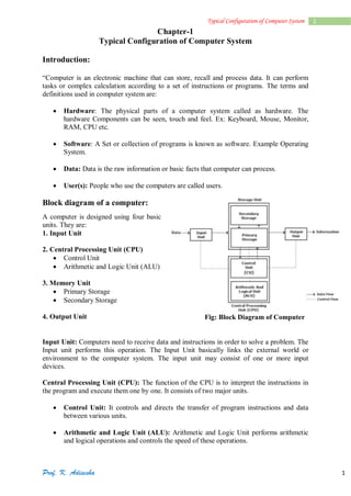
  • 1. Prof. K. Adisesha 1 1Typical Configuration of Computer System Chapter-1 Typical Configuration of Computer System  Introduction: “Computer is an electronic machine that can store, recall and process data. It can perform tasks or complex calculation according to a set of instructions or programs. The terms and definitions used in computer system are:  Hardware: The physical parts of a computer system called as hardware. The hardware Components can be seen, touch and feel. Ex: Keyboard, Mouse, Monitor, RAM, CPU etc.  Software: A Set or collection of programs is known as software. Example Operating System.  Data: Data is the raw information or basic facts that computer can process.  User(s): People who use the computers are called users. Block diagram of a computer: A computer is designed using four basic units. They are: 1. Input Unit 2. Central Processing Unit (CPU)  Control Unit  Arithmetic and Logic Unit (ALU) 3. Memory Unit  Primary Storage  Secondary Storage 4. Output Unit   Fig: Block Diagram of Computer Input Unit: Computers need to receive data and instructions in order to solve a problem. The Input unit performs this operation. The Input Unit basically links the external world or environment to the computer system. The input unit may consist of one or more input devices. Central Processing Unit (CPU): The function of the CPU is to interpret the instructions in the program and execute them one by one. It consists of two major units.  Control Unit: It controls and directs the transfer of program instructions and data between various units.  Arithmetic and Logic Unit (ALU): Arithmetic and Logic Unit performs arithmetic and logical operations and controls the speed of these operations.
  • 2. Prof. K. Adisesha 2 2Typical Configuration of Computer System Memory Unit: The results generated from processing have to be preserved before it is displayed. The memory units thus provide space to store input data, intermediate results and the final Output generated. Output Unit: It is used to print or display the results, which are stored in the memory unit. The actual function of the output unit is just the reverse of the input unit. Thus, the output unit links the computer to the outside world.  Motherboard: The motherboard is a large Printed Circuit Board (PCB), called as main circuit board of the computer, which contains the CPU, memory, expansions slots, bus, video controller and other electronic components. Characteristics of Motherboard: The motherboard is characterized by the form factor, chipset and type of processor socket used.  Form factor refers to the motherboard’s geometry, dimensions, arrangement and electrical requirements.  Chipset controls the majority of resources of the computer. The function of chipset is to coordinate data transfer between the various components of the computer.  The processor socket may be a rectangular connector into which the processor is mounted vertically, or a square shaped connector with many small connectors into which the processor is directly inserted.  Types of Motherboard: There are four different types in motherboard: XT Motherboards: XT stands for Extended Technology. These are old model motherboards. In this we find old model processor socket like LIF (Low Insertion Force) sockets, RAM slots: DIMM (Dual Inline Memory Modules) and ISA (Industry Standards Architecture) slots, 12 pin power connector. They have slot type processors and no ports. Ex: Pentium-I, Pentium-MMX, Pentium-II and Pentium-Pro. AT Motherboards: Advanced Technology Motherboard. AT Motherboards have PGA (Pin Grid Array) socket, SD RAM slots, 20 pin power connector PCI slots and ISA slots. Full AT is 12” wide X 13.8” deep. AT has 5-pin large keyboard connector. Ex: Pentium-III Processors. Baby AT Motherboards: Baby AT motherboards have the combination of XT and AT. It was the first PC motherboard to build in sockets for I/O ports, which were cabled to connectors on the back of the case. Ex: Pentium-III and Pentium-IV ATX Motherboards: Advanced Technology Extended Motherboard. Latest Motherboard all are called as ATX motherboard, designed by ATX form factor. In this motherboard, MPGA Processor sockets, DDRRAM Slots, AGP Slots, SATA Connectors, 20 pin and 24 pin ATX power connector and ports. It is a full size board measuring 12” wide by 9.6” deep. Micro ATX is a small motherboard size of 9.6” X 9.6”. Ex: Pentium-IV, Dual Core, Core 2 Duo, Quad Core, i3, i5 and i7.
  • 3. Prof. K. Adisesha 3 3Typical Configuration of Computer System General Structure of Motherboard The primary function of the processor is to execute the instructions given to it & produce the results.  It fetches instructions and data from the primary memory and performs the required operations.  North Bridge and South Bridge are two chips in core logic chipset on PC motherboard.  North Bridge or north chipset is responsible for control of high speed components like CPU, RAM, Chipset, BUS speed control and switch control data, ensuring data back and forth between the components in a smooth and continuous, fully exploit the speed of the CPU and RAM.  South Bridge or south chipset is similar as north chipset, but the south bridge driver chipset components slower as: Sound Card, Net Card, hard disk, etc. Fig: Structure of ATX Motherboard
  • 4. Prof. K. Adisesha 4 4Typical Configuration of Computer System Components of Motherboard: The motherboard components are:  Processors (CPU)  BIOS  CMOS  Slots  Disk Controllers  I/O Ports and Interfaces  BUS Processors (CPU): The processors or CPU is the main component on the motherboard and is called the brain of the computer. CPU consists of 1) ALU 2) CU 3) Registers Arithmetic and logic unit performs all the arithmetic and logic operations on data. CU is responsible for organizing the processing of data and instructions. Registers is a temporary storage areas for holding data and instructions. Note: Clock Speed: A measure of a processor’s operating speed, currently measured in MHz (Megahertz) and GHz (Gigahertz). A CPU’s performance is measured by the number of instructions executed per second i.e. MIPS & BIPS Microprocessor: It is an electronic component. It is a single integrated circuit (IC) Chip. This tiny chip contains the entire computation engine. Example: Intel, AMD, Celeron. BIOS (Basic Input Output System): BIOS is a small chip on the motherboard that holds a set of instructions to load the hardware settings required like keyboard, monitors or disk drives. The BIOS runs when the computer is switched ON. POST (Power On Self-Test) It checks if the hardware devices are present and functioning properly. BIOS include the bootstrap loader to load the OS into memory. CMOS (Complementary Metal Oxide Semiconductor): It is a type of memory chip to store date, time and system setup parameters. These parameters are loaded every time the computer is started. BIOS & CMOS are kept powered by a small lithium Ion battery located on motherboard. Slots: Slot: A slot is an opening space in a computer where we can insert a printed circuit board. Slots are often called expansion slots. There are several types of slots are: ISA (Industry Standard Architecture): ISA slot is used to connect modem and input devices. PCI (Peripheral Component Interconnect): PCI slots are used to connect graphics accelerators cards, sound card, internal modems or SCSI cards. They are much faster than ISA cards.
  • 5. Prof. K. Adisesha 5 5Typical Configuration of Computer System AGP (Accelerated Graphic Port): AGP slot is an advanced port designed for video cards and 3D accelerators. RAM Slot: RAM slot is used to install memory to store programs and data currently being used by CPU. RAM is measured in units called bytes. Two types of RAM slot  SIMM (Single Inline Memory Module)  DIMM (Dual Inline Memory Module) Processor Slot: Processor slot is used to insert the processor chip which is the largest chip on the motherboard. Disk Controllers: A device that connects a disk drive to the computer’s bus enabling the drive to exchange data with other device. Hard Disk Controller (HDC): The HDC is the interface that enables the computer to read and write information to the hard disk drive. This connector is used to insert an Integrated Digital Electronics (IDE) cable. IDE cables connect devices such as hard drives, CD drives and DVD drives.  Floppy Disk Controller (FDC): FDC is the interface that directs and controls reading from and writing to computer floppy disk drive. FDC usually performs data transmission in Direct Memory Access (DMA) mode. I/O Ports and Interfaces: Port: A port is a socket on the computer used to connect external device to the computer. It is used to connect external device like printer, keyboard or scanner. The different types of I-O ports are Serial port, Parallel port, USB port and VGA port. Serial Port: Serial Port, also known as communication port or Rs-232 c ports, is used for connecting communication devices like mouse and modem. They are used for connecting communication devices like mouse, modem. This port transfers data serially one bit at a time. One main advantage is that data is sent and received over only two lines. Parallel Port: Parallel ports are used to connect external input/output devices like printers or scanners. Also known as printer port. They carry 8 bit (one byte) at a time. USB port: USB (Universal Serial BUS) port is used to connect a variety of newer peripherals like printers, scanners, digital cameras, web cameras, speakers, etc. to a computer. USB port gives a single, standardized, easy-to-use way to connect a variety of newer peripherals to a computer.  USB is a plug-and-play interface between a computer and add-on devices such as audio players, modem, scanner etc.  With USB, a new device can be added to your computer without adding a adapter card or even turning the computer off.  USB supports a data speed of 12 megabits per second.  USB supporting up to 127 devices. PS-2 (Personal System) port: PS-2 port was developed by IBM to interface keyboards and pointing devices like mouse, trackballs and touch pads.
  • 6. Prof. K. Adisesha 6 6Typical Configuration of Computer System IDE (Integrated Digital Electronics) port: It connects IDE devices like CD-ROM drives or hard disk drives to the motherboard. AGP (Accelerated Graphics Port) port: It is used to connect to graphic card that provides high-speed video performance typically required in games and other multimedia applications. VGA (Visual Graphics Adaptor) port: It connects monitor to a computer’s video card. Modem (Modulator demodulator): connects a PC to the telephone network. Ethernet port connects to a network and high speed Internet. It connects network cable to a computer. MIDI (Musical Instrument Digital Interface) port is a system designed to transmit information between electronic musical instruments. Bus: A bus is a collection of parallel wires that form a pathway to carry address, data and control signal. The functional features of bus are:  A bus is a set of wire and each wire can carry one bit of data.  A bus width is defined by the number of wires in the bus A computer bus can be divided into two types: Internal Bus:  It connects major computer components like processor, memory & I/O.  It is also called as system bus. External Bus:  It connects the different external devices peripheral, expansion slots, I/O ports to the rest of the computer.  It is also called the expansion bus and is slower than the system (internal) bus. A system bus or expansion bus comprise of three kinds of buses:
  • 7. Prof. K. Adisesha 7 7Typical Configuration of Computer System Data Bus:  It provides a path to transfer data between CPU and memory.  The data bus may consists of 32, 64, 128 lines of wire. Address Bus:  It connects CPU & RAM with a set of lines similar to data bus.  The address bus width determines the maximum number of memory location the computer can address. Control Bus:  It is used to control the access to and the use of the data and address lines. Memory: A computer memory refers to the electronic storing space for instructions and data. Two kinds of memory are commonly used:  Primary or Main Memory  Secondary Memory Primary Memory: It is the main memory of the computer. It stores programs and data that is currently needed by CPU. Functions of primary memory:  To contain a copy of the main software program i.e. operating system. This program is loaded into the primary memory when the computer is turned on.  Temporarily store a copy of the application program.  Temporarily store the data input from the keyboard.  Temporarily store the result which is generated from processing until it is transferred to output device. Primary memory is of two types.  RAM (Random Access Memory)  ROM (Read Only Memory) Random Access Memory (RAM): RAM is also known as main memory of a computer. RAM temporarily stores the computer operating system, application program and current data so that the processor can reach them quickly. RAM is faster memory. RAM is a volatile in nature i.e. when the power is switched off; the data in this memory is lost. Types of RAM Static RAM (SRAM)  Static RAM chip is usually used in cache memory due to its high speed.  It stores information as long as the power supply is on.  SRAM is more expensive than DRAM and it takes up more space. Dynamic RAM (DRAM)  It is the most common type of memory chip.  DRAM is cheaper and they consume less power.  It uses transistor and capacitors. They are further classified as  SDRAM: stands for Synchronous Dynamic RAM. It is synchronized to the system clock. Since it is synchronized to the CPU, it knows when the next cycle is coming and has the data ready when the CPU requests it.
  • 8. Prof. K. Adisesha 8 8Typical Configuration of Computer System  DDR RAM: stands for Double Data Rate RAM. It works same as SD RAM but the data transfer rate is double when compared to SD RAM. Different types of DDR RAM are DDR1, DDR2, and DDR3. Read Only Memory (ROM): ROM stands for “Read Only memory”. ROM is non-volatile memory i.e. the information stored in it is not lost even when the power supply goes off. It is used for permanent storage of information. Difference between RAM and ROM:  Read Only Memory (ROM)  Read Only Memory (ROM) 1. Random Access Memory 2. Volatile(maintains its data while the device is powered) 3. Stores information temporary 4. Requires flow of electricity to retain data 5. Large size with higher capacity 6. Used for both read and write 7. Costlier 8. Very fast but uses a lot of power 9. Used in CPU cache, primary memory 1. Read only Memory 2. Non-Volatile (does not lose content when power is lost) 3. Stores information permanently 4. Does not require flow of electricity to retain data 5. Small size with less capacity 6. Used only for reading 7. Cheaper than RAM 8. Fast but uses very little power 9. Used in firmware, micro-controllers  Secondary Memory:  Secondary memory is also known as External memory or Auxiliary memory  In secondary memory, data is first transferred to main memory and then routed to processing unit.  Magnetic disk, optical disks are used to store information in secondary memory.  Information stored is permanent unless one deletes it intentionally.  Data stored is not uniform in secondary memory.  Secondary memory devices are less expensive when compare to primary memory devices.  It is always Non-volatile in nature.  It is little slow in interacting with microprocessor.  Whereas secondary memory can store bulk amounts of data in a single unit.  Examples: Magnetic Tapes, Optical Disc, Floppy Disks, Flash memory [USB drives], Paper Tape, Punched cards etc. Cache Memory: The cache memory is a high-speed memory placed in between RAM and CPU. Cache memory stores data that is used more often, temporarily and makes it available to CPU at fast rate. Hence, it is used to increase the speed of processing. Cache memory is very expensive, so it is smaller. Cache memory of sizes 256 KB to 2 MB. It is categorized as “levels”.  Level 1 (L1) cache: It is extremely fast but relatively small and is usually present inside the CPU. The size of L1 cache varies from 32 KB to 512 KB.  Level 2 (L2) cache: It may be located outside the CPU on a separate chip a high speed system bus interconnecting the cache to the CPU. The size of L2 cache varies from 1MB to 2MB.
  • 9. Prof. K. Adisesha 9 9Typical Configuration of Computer System  Level 3 (L3) cache: It is typically specialized memory that works to improve the performance of L1 and L2. It is slower the L1 or L2 but it is usually double the speed of RAM. Fig: Structure of Cache Memory  Switch Mode Power Supply: SMPS stands for Switch Mode Power Supply. An SMPS converts AC power from an electrical outlet to DC power needed by system components. The SMPS contains the power card plug, a fan for cooling because it generates a lot of heat. UPS: UPS stands for “Uninterruptible Power Supply”. An UPS is a power supply that includes a battery to maintain power in the event a power failure. An UPS keeps a computer running for several minutes to few hours after a power failure. There are two types of UPS Offline UPS:  Also known as “Standby UPS”  Offline UPS monitors the power line and switches to battery power as soon as it detects a problem. Online UPS:  An online UPS continuously provides power from its own inverter, even when the power line is functioning properly.  Online UPS is more costly than offline UPS.
  • 10. Prof. K. Adisesha 10 10Typical Configuration of Computer System Important Questions  1 Marks Question: 1. What is Microprocessor? 2. What is Motherboard? [June 2015] 3. Expand USB. 4. What is data bus? [March 2015] 5. Which memory is known as main memory? 6. Which memory is considered as working memory of CPU? 7. What is Cache Memory? [June 2016] 8. What is Bus? [March 2017] 9. Expand SDRAM. 10. Expand ISA [March 2016] 11. Expand SMPS.  3 Marks Question: 1. Explain the characteristics of motherboard. [March 2017] 2. Explain three types of motherboard. [June 2016] 3. Mention the components of the motherboard. 4. What is port? Explain serial port. [March 2015] 5. What is meant by plug and play device? Explain. 6. Write any three features of USB. 7. Explain Cache memory. 8. What is the function of UPS? Mention the different types of UPS. [June2015,March 2016]