

Recomendados
Mais conteúdo relacionado
Mais procurados
Mais procurados (20)
Destaque
Destaque (20)
Semelhante a Analysis of state machines
Semelhante a Analysis of state machines (20)
Mais de Abhilash Nair
Mais de Abhilash Nair (20)
Último
Último (20)
Analysis of state machines
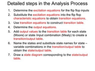
- 1. Detailed steps in the Analysis Process 1. Determine the excitation equations for the flip flop inputs 2. Substitute the excitation equations into the flip flop characteristic equations to obtain transition equations. 3. Use transition equations to construct transition table. 4. Determine the output equations. 5. Add output values to the transition table for each state (Moore) or state /input combination (Mealy) to create a transition/output table. 6. Name the states and substitute state names for state – variable combinations in the transition/output table to obtain the state/output table. 7. Draw a state diagram corresponding to the state/output table.
- 2. Analysis: Example 1 - State Machine Analyze the synchronous state machines shown below. Determine the excitation equations, transition equations and output equations. Construct the transition output table and state output table. Draw the state diagram. X Z Q D Q Clk
- 3. Combinational Logic Input Output X Z Excitation Q D Present Next State State Q Clk Clock Memory 1. Determine the excitation equations for the flip flop inputs D = X ⊕Q
- 4. 2. Substitute the excitation equations into the flip flop characteristic equations to obtain transition equations. Q* = D characteristic equation Q* = X ⊕ Q transition equation 3. Use transition equations to construct transition table. Transition table State Input X Q 0 1 0 0 1 1 1 0 Next State Q*
- 5. 4. Determine the output equations. Z = X ⊕Q output equation 5. Add output values to the transition table for each state (Moore) or state /input combination (Mealy) to create a transition/output table. Transition/output table State Input X Q 0 1 0 0,0 1,1 1 1,1 0,0 Next State Q*, Z
- 6. 6. Name the states and substitute state names for state – variable combinations in the transition/output table to obtain the state/output table. Substituting state names ‘A’ for state Q = 0 & ‘B’ for state Q = 1 S is current state & S* is next state. State/output table State Input X S 0 1 A A,0 B,1 B B,1 A,0 Next State S*, Z
- 7. Draw a state diagram corresponding to the state/output table. State/output table State Input X S 0 1 A A,0 B,1 B B,1 A,0 Next State S*, Z State diagram 1/1 0/0 A B 0/1 1/0
- 8. Analysis: Example 2 - State Machine 8
- 9. Analysis: Example 2 - Excitation Equations 9
- 10. Analysis: Example 2 - Transition Equations • Excitation equations • Characteristic equations • Substitute excitation equations into characteristic equations 10
- 11. Analysis: Ex 2 - Transition/State Tables transition equations output equation transition state table state/output table table 11
- 12. Analysis: Example 2 - State Diagram • Mealy machine state diagram – Circles for states – Arrows for transitions (note output info) 12