

Recomendados
Mais conteúdo relacionado
Mais procurados
Mais procurados (20)
Destaque
Destaque (20)
Semelhante a MSI Counters
Semelhante a MSI Counters (20)
Mais de Abhilash Nair
Mais de Abhilash Nair (20)
MSI Counters
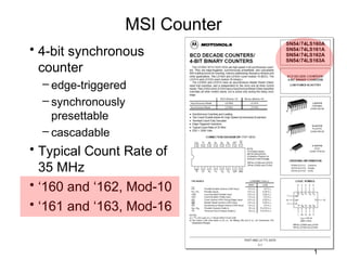
- 1. MSI Counter • 4-bit synchronous counter – edge-triggered – synchronously presettable – cascadable • Typical Count Rate of 35 MHz • ‘160 and ‘162, Mod-10 • ‘161 and ‘163, Mod-16 1
- 2. MSI Counter • 74LS163 4-bit synchronous counter 16-pin DIP 2
- 3. MSI Counter • 74LS163 characteristics – edge-triggered – synchronously presettable – cascadable – count modulo 16 (binary) 74x163 • Synchronous Reset (Clear) input that overrides all other control inputs – active only during the rising clock edge 3
- 4. MSI Counter • 74LS163 logic symbols datasheet text 74x163 4
- 5. MSI Counter • 74LS163 state diagram and logic equations 5
- 6. MSI Counter • 74LS163 mode select table • All signals must be high ( H ) to enable the count sequence to begin 6
- 7. MSI Counter • 74x163 is a synchronous 4-bit binary counter • RCO=1 when all count bits are 1 and ENT is asserted 7
- 8. MSI Counter • The control inputs for the 74x163 have the following effects: clear load hold hold 8
- 9. 74x163 Internal Logic Diagram
- 10. Counter Operation • Free-running ÷16 • Count if ENP and ENT both asserted • Load if LD is asserted (overrides counting) • Clear if CLR is asserted (overrides loading and counting) • All operations take place on rising CLK edge makes it free-running • RCO is asserted if ENT is asserted and Count = 15 10
- 11. Free-Running 4-Bit ’163 Counter • “divide-by-16” counter • RCO is asserted if ENT is asserted and Count = 15 11
- 12. Modified Counting Sequence DCBA • Load 0101 (5) after Count = 15 • 5, 6, 7, 8, 9, 10, 11, 12, 13, 14, 15, 5, 6, … • “divide-by-11” counter 12
- 13. Another Way • Clear after Count = 1010 (10) • 0, 1, 2, 3, 4, 5, 6, 7, 8, 9, 10, 0, 1, 2, 3, … • “modulo-11” or “divide-by-11” counter 13
- 14. Counting from 3 to 12 14
- 15. Cascading Counters • For modulus greater than 16 • RCO (ripple carry out) is asserted in state 15, if ENT is asserted 15
- 16. Decoding Binary-Counter States • A binary counter may be combined with a decoder to obtain a set of 1-out-of-m coded signals, where one signal is asserted in each counter state Useful when counter outputs are used to control a set of devices A different device is enabled in each counter state In this approach each output of the decoder enables a different device The next slide shows the 74163 wired as a modulo 8 counter combined with a 74138 (3 to 8 decoder) The decoder output provides eight signals, each one representing a counter state 16
- 18. Decoding Binary-Counter States • The next slide shows a typical timing diagram for this circuit • Each decoder output is asserted during a corresponding clock period • The decoder outputs may contain “glitches” on state transitions where two or more counter bits change • This happens even though the 74163 outputs are glitch free and the 74138 does not have any static hazards • In a synchronous counter like the 74163 the outputs don’t change exactly at the same time • Moreover multiple signal paths in a decoder like 74138 have different delays; thus the output may have glitches • This problem is an example of functional hazard 18
- 19. Decoder Waveforms • Glitches may or may not be a concern 19
- 20. Glitch-Free Outputs • In most applications these would be used as control inputs to counters, registers and other edge triggered devices • In such a case there is no problem as the glitches occur after the clock tick • They would be a problem if applied to latches • They would also be a problem if utilized as a clock • One way to “clean-up” these glitches is to connect the 74138 decoder output to another register • This register would sample the stable decoded outputs on the next clock tick as shown in the next slide • In this case the final outputs would have to be renamed to account for the one clock tick delay through the register 20
- 21. Glitch-Free Outputs • Register outputs delayed by one clock cycle 21
- 22. 74161 MSI Counter • The 74163 is fully synchronous • Some applications require an asynchronous clear function • That is provided by 74161 • It has the same pinout as 74163 • Its CLR_L input is connected to the asynchronous clear inputs of its flip flops
- 23. Modulo-10 Counters • From the 74LS163 “family” – the 74LS160 – 74LS160 in free-running mode – Duty cycle of QC and QD is not 50% 23
- 24. Modulo-10 Counters • 74LS160 state diagram • The 74LS160 (and 74LS162) can be preset to any state, but will not count beyond 9. • If preset to state 10, 11, 12, 13, 14, or 15, it will return to its normal sequence within two clock pulses. • 74160 has asynchronous clear as in 74161 24
- 25. Up/Down Counters • A 3-bit binary up/down counter (block diagram) QA Clock QB Counter Count QC UP / DOWN 25
- 26. Up/Down Counters • A 3-bit binary up/down counter (State diagram) 26
- 27. Up/Down Counters 27
- 28. Up/Down Counters • This circuit is a 3-bit UP/DOWN synchronous counter using JK flip-flops configured to operate as toggle or T-type flip- flops giving a count of zero (000) to seven (111) and back to zero again. • An additional input determines the direction of the count, either UP or DOWN and the timing diagram gives an example of the counters operation as this UP/DOWN input changes state. 28
- 29. Timing diagram
- 30. Up/Down Counters • The 74LS169 is a fully synchronous 4-stage up/down counter • Includes: – a preset capability for programmable operation – carry lookahead for easy cascading – a U/ D input to control the direction of counting 30
- 31. Up/Down Counters • The SN74LS169 operates in a Modulo-16 binary sequence 31
- 32. 74LS169 logic circuit diagram
- 33. Up/Down Counters • 74LS169 logic symbol • Functions similar to 74163 • Difference is that its carry output and enable inputs are active low • It is an up/down counter • It counts ascending or descending binary order depending on the value of input signal UP/DN • Counts up when UP/DN is 1 • Counts down when UP/DN is 0 33
- 34. MSI Counters • 7458: Dual 4-bit Decade Counter • 74454: Dual Decade Up/Down Counter, Synchronous, Preset Input • 7459: Dual 4-bit Binary Counter • 74455: Dual Binary Up/Down Counter, Synchronous, Preset Input • 7468: Dual 4 Bit Decade or Binary Counters • 74461: 8-bit Presettable Binary Counter with three-state outputs • 7469: Dual 4 Bit Decade or Binary Counters • 74490: Dual Decade Counter • 7490: Decade Counter (separate Divide-by-2 and Divide-by-5 sections) • 74491: 10-bit Binary Up/Down Counter with Limited Preset and three-state • 7492: Divide-by-12 Counter (separate Divide-by-2 and Divide-by-6 logic outputs sections) • 74560: 4-bit Decade Counter with three-state outputs • 7493: 4-bit Binary Counter (separate Divide-by-2 and Divide-by-8 sections) • 74561: 4-bit Binary Counter with three-state outputs • 74142: Decade Counter/Latch/Decoder/Nixie Tube Driver • 74568: Decade Up/Down Counter with three-state outputs • 74143: Decade Counter/Latch/Decoder/7-segment Driver, 15 mA Constant • 74569: Binary Up/Down Counter with three-state outputs Current • 74590: 8-Bit Binary Counter with Output Registers and three-state outputs • 74144: Decade Counter/Latch/Decoder/7-segment Driver, 15V open • 74592: 8-Bit Binary Counter with Input Registers collector outputs • 74593: 8-Bit Binary Counter with Input Registers and three-state outputs • 74160: Synchronous 4-bit Decade Counter with Asynchronous Clear • 74668: Synchronous 4-bit Decade Up/Down Counter • 74161: Synchronous 4-bit Binary Counter with Asynchronous Clear • 74669: Synchronous 4-bit Binary Up/Down Counter • 74162: Synchronous 4-bit Decade Counter with Synchronous Clear • 74690: 4-bit Decimal Counter/Latch/Multiplexer with Asynchronous Reset, • 74163: Synchronous 4-bit Binary Counter with Synchronous Clear Three-State Outputs • 74168: Synchronous 4-Bit Up/Down Decade Counter • 74691: 4-bit Binary Counter/Latch/Multiplexer with Asynchronous Reset, • 74169: Synchronous 4-Bit Up/Down Binary Counter Three-State Outputs • 74176: Presettable Decade (Bi-Quinary) Counter/Latch • 74692: 4-bit Decimal Counter/Latch/Multiplexer with Synchronous Reset, • 74177: Presettable Binary Counter/Latch Three-State Outputs • 74190: Synchronous Up/Down Decade Counter • 74693: 4-bit Binary Counter/Latch/Multiplexer with Synchronous Reset, • 74191: Synchronous Up/Down Binary Counter Three-State Outputs • 74694: 4-bit Decimal Counter/Latch/Multiplexer with Synchronous and • 74192: Synchronous Up/Down Decade Counter with Clear Asynchronous Resets, three-state outputs • 74193: Synchronous Up/Down Binary Counter with Clear • 74695: 4-bit Binary Counter/Latch/Multiplexer with Synchronous and • 74196: Presettable Decade Counter/Latch Asynchronous Resets, three-state outputs • 74197: Presettable Binary Counter/Latch • 74696: 4-bit Decimal Counter/Register/Multiplexer with Asynchronous • 74290: Decade Counter (separate divide-by-2 and divide-by-5 sections) Reset, three-state outputs • 74291: 4-bit Universal Shift register, Binary Up/Down Counter, • 74697: 4-bit Binary Counter/Register/Multiplexer with Asynchronous Synchronous Reset, three-state outputs • 74293: 4-bit Binary Counter (separate divide-by-2 and divide-by-8 • 74698: 4-bit Decimal Counter/Register/Multiplexer with Synchronous sections) Reset, three-state outputs • 74390: Dual 4-bit Decade Counter • 74699: 4-bit Binary Counter/Register/Multiplexer with Synchronous Reset, • 74393: Dual 4-bit Binary Counter three-state outputs • 74452: Dual Decade Counter, Synchronous • 74716: Programmable Decade Counter • 74453: Dual Binary Counter, Synchronous • 74718: Programmable Binary Counter 34
- 35. 35