Mais conteúdo relacionado Semelhante a Advance structure system Notes 2 (20) 3. Dome shells–might be domical shell
structures
A rounded roof, with a circular base, shaped like an arch in all directions.. First
used in much of the Middle East and North Africa whence it spread to other
parts of the Islamic world, because of its distinctive form the dome has, like the
minaret, become a symbol of Islamic architecture.
Dome has double curvature and the resulting structure is much stiffer and stronger than
a single curved surface, such as a barrel shell
5.
Beams are characterized by their profile (the shape of their cross‐section), their length, and their material.
In contemporary construction, beams are typically made of steel, reinforced concrete, wood, composites,
or cased fluids (inflatable beams). One of the most common types of steel beam is the I‐beam or wide‐
flange beam (also known as a "universal beam" or, for stouter sections, a "universal column"). This is
commonly used in steel‐frame buildings and bridges. Other common beam profiles are the C‐channel,
the hollow structural section beam, the pipe, and the angle.
Beams are also described by how they are supported. Supports restrict lateral and/or rotational
movements so as to satisfy stability conditions as well as to limit the deformations to a certain allowance.
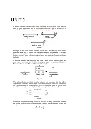
A simple beam is supported by a pin support at one end and a roller support at the other end. A beam with
a laterally and rotationally fixed support at one end with no support at the other end is called
a cantilever beam. A beam simply supported at two points and having one end or both ends extended
beyond the supports is called an overhanging beam.
Structural characteristics
Moment of inertia
The moment of inertia of an object about a given axis describes how difficult it is to change its angular
motion about that axis. Therefore, it encompasses not just how much mass the object has overall, but how
far each bit of mass is from the axis. The farther out the object's mass is, the more rotational inertia the
object has, and the more force is required to change its rotation rate.
Diagram of stiffness of a simple square beam (A) and universal beam (B). The universal beam flange
sections are three times further apart than the solid beam's upper and lower halves. The second moment
6. of inertia of the universal beam is nine times that of the square beam of equal cross section (universal
beam web ignored for simplification)
Stress in beams
Internally, beams experience compressive, tensile and shear stresses as a result of the loads applied to
them. Typically, under gravity loads, the original length of the beam is slightly reduced to enclose a smaller
radius arc at the top of the beam, resulting in compression, while the same original beam length at the
bottom of the beam is slightly stretched to enclose a larger radius arc, and so is under tension. The same
original length of the middle of the beam, generally halfway between the top and bottom, is the same as
the radial arc of bending, and so it is under neither compression nor tension, and defines the neutral axis
(dotted line in the beam figure). Above the supports, the beam is exposed to shear stress. There are
some reinforced concrete beams in which the concrete is entirely in compression with tensile forces taken
by steel tendons. These beams are known as prestressed concrete beams, and are fabricated to produce a
compression more than the expected tension under loading conditions. High strength steel tendons are
stretched while the beam is cast over them. Then, when the concrete has cured, the tendons are slowly
released and the beam is immediately under eccentric axial loads. This eccentric loading creates an internal
moment, and, in turn, increases the moment carrying capacity of the beam. They are commonly used on
highway bridges.
The primary tool for structural analysis of beams is the Euler–Bernoulli beam equation. Europe has
superseded Euler‐Bernoulli equations with the Perry Robertson formula. Other mathematical methods for
determining the deflection of beams include "method of virtual work" and the "slope deflection method".
Engineers are interested in determining deflections because the beam may be in direct contact with
a brittle material such as glass. Beam deflections are also minimized for aesthetic reasons. A visibly sagging
beam, even if structurally safe, is unsightly and to be avoided. A stiffer beam (high modulus of
elasticity and high second moment of area) produces less deflection. Mathematical methods for
determining the beam forces (internal forces of the beam and the forces that are imposed on the beam
support) include the "moment distribution method", the force or flexibility method
CONCRETE SLAB
A concrete slab is a common structural element of modern buildings. Horizontal slabs of steelreinforced
concrete, typically between 100 and 500 millimeters thick, are most often used to construct floors and
ceilings, while thinner slabs are also used for exterior paving.
In many domestic and industrial buildings a thick concrete slab, supported on foundations or directly on
thesubsoil, is used to construct the ground floor of a building. These can either be "ground‐bearing" or
"suspended" slabs. In high rise buildings and skyscrapers, thinner, pre‐cast concrete slabs are slung
between the steel frames to form the floors and ceilings on each level.
On the technical drawings, reinforced concrete slabs are often abbreviated to "r.c.slab" or simply "r.c."
hod and the direct stiffness method.
7. Design
For a suspended slab, there are a number of designs to improve the strength‐to‐weight ratio. In all cases
the top surface remains flat, and the underside is modulated:
Corrugated, usually where the concrete is poured into a corrugated steel tray. This improves strength
and prevents the slab bending under its own weight. The corrugations run across the short dimension,
from side to side.
A ribbed slab, giving considerable extra strength on one direction.
A waffle slab, giving added strength in both directions.
Reinforcement design
A one way slab needs moment resisting reinforcement only in its short‐direction because the moment
along long axes is so small that it can be neglected. When the ratio of the length of long direction to
short direction of a slab is greater than 2 it can be considered as a one way slab.
A two way slab needs moment resisting reinforcement in both directions. If the ratio of the lengths of
long and short side is less than two then movement in both direction should be considered in design.
Construction
A concrete slab may be prefabricated or in situ. Prefabricated concrete slabs are built in a factory
and transported to the site, ready to be lowered into place between steel or concrete beams. They
may be pre‐stressed (in the factory), post‐stressed (on site), or unstressed. It is vital that the
supporting structure is built to the correct dimensions, or the slabs may not fit.
In situ concrete slabs are built on the building site using formwork ‐ a type of boxing into which the
wet concrete is poured. If the slab is to be reinforced, the rebars are positioned within the
formwork before the concrete is poured in. Plastic tipped metal, or plastic bar chairs are used to
hold the rebar away from the bottom and sides of the form‐work, so that when the concrete sets it
completely envelops the reinforcement. For a ground slab, the form‐work may consist only of
sidewalls pushed into the ground. For a suspended slab, the form‐work is shaped like a tray, often
supported by a temporary scaffold until the concrete sets.
The formwork is commonly built from wooden planks and boards, plastic, or steel. On commercial
building sites today, plastic and steel are more common as they save labour. On low‐budget sites,
for instance when laying a concrete garden path, wooden planks are very common. After the
concrete has set the wood may be removed, or left there permanently.
In some cases formwork is not necessary ‐ for instance, a ground slab surrounded by brick or block
foundation walls, where the walls act as the sides of the tray and hardcore acts as the base.
8.
ARCH
An arch is a structure that spans a space and supports structure and weight above it. Arches appeared as
early as the 2nd millennium BC in Mesopotamian brick architecture and their systematic use started with
the Ancient Romans who were the first to apply the technique to a wide range of structures.
An arch is a pure compression form. It can span a large area by resolving forces into compressive
stresses and, in turn eliminating tensile stresses. This is sometimes referred to as arch action. As the forces
in the arch are carried to the ground, the arch will push outward at the base, called thrust. As the rise, or
height of the arch decreases, the outward thrust increases.[4]
In order to maintain arch action and prevent
the arch from collapsing, the thrust needs to be restrained, either with internal ties, or external bracing,
such as abutments.
Fixed arch vs. hinged arch
The most common true arch configurations are the fixed arch, the two‐hinged arch, and the three‐hinged
arch.
The fixed arch is most often used in reinforced concrete bridge and tunnel construction, where
the spans are short. Because it is subject to additional internal stress caused by thermal
expansion and contraction, this type of arch is considered to be statically indeterminate.
The two‐hinged arch is most often used to bridge long spans. This type of arch has pinned
connections at the base. Unlike the fixed arch, the pinned base is able to rotate, allowing the
structure to move freely and compensate for the thermal expansion and contraction caused by
changes in outdoor temperature. Because the structure is pinned between the two base
connections, which can result in additional stresses, the two‐hinged arch is also statically
indeterminate, although not to the degree of the fixed arch
The three‐hinged arch is not only hinged at its base, like the two‐hinged arch, but at the mid‐
span as well. The additional connection at the mid‐span allows the three‐hinged arch to move in
two opposite directions, and compensate for any expansion and contraction. This type of arch is
thus not subject to additional stress caused by thermal change. The three‐hinged arch is
therefore said to be statically determinate.[6]
It is most often used for medium‐span structures,
such as large building roofs.
Another advantage of the three‐hinged arch is that the pinned bases are more easily developed
than fixed ones, allowing for shallow, bearing‐type foundations in medium‐span structures. In the
three‐hinged arch, "thermal expansion and contraction of the arch will cause vertical movements at
the peak pin joint but will have no appreciable effect on the bases," further simplifying the
foundation design.
Types of arches
9. Arches have many forms, but all fall into three basic categories: Circular, pointed, and parabolic. Arches can
also be configured to produce vaults and arcades.[5]
Arches with a circular form, also referred to as rounded arch, were commonly employed by the
builders of ancient, heavy masonry arches. Ancient Roman builders relied heavily on the
rounded arch to span large, open areas. Several rounded arches placed in‐line, end‐to‐end,
form an arcade, such as the Roman aqueduct
Pointed arches were most often used by builders of Gothic‐style architecture. The advantage to
using a pointed arch, rather than a circular arch, is that the arch action in a pointed arch
produces less thrust at the base. This innovation allowed for taller and more closely spaced
openings, typical of Gothic architecture.
Vaults are essentially "adjacent arches [that] are assembled side by side." If vaults intersect,
complex forms are produced with the intersections. The forms, along with the "strongly
expressed ribs at the vault intersections, were dominant architectural features of Gothic
cathedrals."
The parabolic arch employs the principle that when weight is uniformly applied to an arch, the
internal compression resulting from that weight will follow a parabolic profile. Of any arch type,
the parabolic arch produces the most thrust at the base, but can span the largest areas. It is
commonly used in bridge design, where long spans are needed.
10.
Force distribution in different types of arches
CATENARY
In physics and geometry, a catenary is the curve that an idealized hanging chain or cable assumes under its
own weight when supported only at its ends. The curve has a U‐like shape, superficially similar in
appearance to a parabola (though mathematically quite different). It also appears in the design of certain
types of arches and as a cross section of the catenoid—the shape assumed by a soap film bounded by two
parallel circular rings.
The catenary is also called the "alysoid", "chainette", or, particularly in the material sciences, "funicular".
Mathematically, the catenary curve is the graph of the hyperbolic cosine function. The surface of
revolution of the catenary curve, the catenoid, is a minimal surface, and is the only minimal surface of
revolution other than the plane. Catenaries and related curves are used in architecture and engineering, in
the design of bridges and arches, so that forces do not result in bending moments.
11. Inverted catenary arch
Catenary arches are often used in the construction of kilns. To create the desired curve, the shape of a
hanging chain of the desired dimensions is transferred to a form which is then used as a guide for the
placement of bricks or other building material.
The Gateway Arch in St. Louis, Missouri, United States is sometimes said to be an (inverted) catenary, but
this is incorrect. It is close to a more general curve called a flattened catenary, with
equation y = A cosh(B x ), which is a catenary if A B = 1 .
Catenary bridges
In free‐hanging chains, the force exerted is uniform with respect to length of the chain, and so the chain
follows the catenary curve. The same is true of a simple suspension bridge or "catenary bridge," where the
roadway follows the cable.
A stressed ribbon bridge is a more sophisticated structure with the same catenary shape. However in
a suspension bridge with a suspended roadway, the chains or cables support the weight of the bridge, and
so do not hang freely. In most cases the roadway is flat, so when the weight of the cable
is negligible compared with the weight being supported, the force exerted is uniform with respect to
horizontal distance, and the result is a parabola, as discussed below (although the term "catenary" is often
still used, in an informal sense). If the cable is heavy then the resulting curve is between a catenary and a
parabola
12. VAULT
A Vault is an architectural term for an arched form used to provide a space with a ceiling or roof. The parts
of a vault exert lateral thrust that require a counter resistance. When vaults are built underground, the
ground gives all the resistance required. However, when the vault is built above ground, various
replacements are employed to supply the needed resistance. An example is the thicker walls used in the
case of barrel or continuous vaults. Buttresses are used to supply resistance when intersecting vaults are
employed.
The simplest kind of vault is the barrel vault (also called a wagon or tunnel vault) which is
generally semicircular in shape. The barrel vault is a continuous arch, the length being greater than its
diameter. As in building an arch, a temporary support is needed while rings of voussoirs are constructed
and the rings placed in position. Until the topmost voussoir, the keystone, is positioned the vault is not self‐
supporting. Where timber is easily obtained, this temporary support is provided by centering consisting of
a framed truss with a semicircular or segmental head, which supports the voussoirs until the ring of the
whole arch is completed. With a barrel vault, the centering can then be shifted on to support the next
rings.
Vault types
Dome
Amongst the earliest known examples of any form of vaulting is to be found in the neolithic village
of Khirokitia on Cyprus. Dating from ca. 6000 BCE, the circular buildings supported beehive
shaped corbel domed vaults of unfired mud‐bricks and also represent the first evidence for settlements
with an upper floor. Similar Beehive tombs, called tholoi, exist in Crete and Northern Iraq. Their
construction differs from that at Khirokitia in that most appear partially buried and make provision for
a dromos entry.
The inclusion of domes, however, represents a wider sense of the word vault. The distinction between the
two is that a vault is essentially an arch which is extruded into the third dimension, whereas a dome is an
arch revolved around its vertical axis.
Barrel vault
A barrel vault is the simplest form of a vault and resembles a barrel or tunnel cut lengthwise in half. The
effect is that of a structure composed of continuous semicircular or pointed sections.
The earliest known examples of barrel vaults were built by the Sumerians, possibly under
the ziggurat at Nippur in Babylonia, which was built of fired bricks cemented with clay mortar.
Groin vault
A groin vault or groined vault (also sometimes known as a double barrel vault or cross vault) is produced
by the intersection at right angles of two barrel vaults. The word groin refers to the edge between the
13. intersecting vaults. Sometimes the arches of groin vaults are pointed instead of round. In comparison with
a barrel vault, a groin vault provides good economies of material and labor. The thrust is concentrated
along the groins or arises (the four diagonal edges formed along the points where the barrel vaults
intersect), so the vault need only be abutted at its four corners.
Rib vault
The intersection of two or three barrel vaults produces a rib vault or ribbed vault when they are edged
with an armature of piped masonry often carved in decorative patterns; compare groin vault, an older form
of vault construction. While the mechanics of the weight of a groin vault and its transmission outwards to
the supporting pillars remained as it had been, the new use of rib vaults demonstrates the skill of the
masons and the grandeur of the new ideas circulating at the introduction of Gothic architecture in the end
of the eleventh century. This technique was new in the late eleventh century, for example in the roofs of
the choir side aisles at Durham Cathedral. Ancestors of the Gothic rib vault in the Romanesque vaults can
be found at Caen and Durham, both sites of early Gothic constructions, and elsewhere.
DOMES
A dome is an element of architecture that resembles the hollow upper half of a sphere. Dome structures
made of various materials have a long architectural lineage extending into prehistory. A dome can be
thought of as an arch which has been rotated around its central vertical axis. Thus domes, like arches, have
a great deal of structural strength when properly built and can span large open spaces without interior
supports. Corbel domes achieve their shape by extending each horizontal layer of stones inward slightly
farther than the previous, lower, one until they meet at the top. These are sometimes
called false domes. True, or real, domes are formed with increasingly inward‐angled layers
of voussoirs which have ultimately turned 90 degrees from the base of the dome to the top. The optimal
shape for a masonry dome of equal thickness is a catenary curve, similar to the curve of a parabola. This
shape provides for perfect compression, without any of the tension or bending forces against which
masonry is weak. Hemispherical domes, by contrast, generate significant horizontal thrusts at their
haunches
.
TRUSSES
In architecture, a truss is a structure comprising one or more triangular units constructed with straight
members whose ends are connected at joints referred to as nodes. External forces and reactions to those
forces are considered to act only at the nodes and result in forces in the members which are either
tensile or compressive forces. Moments (torques) are explicitly excluded because, and only because, all the
joints in a truss are treated as revolute.
14. A planar truss is one where all the members and nodes lie within a two dimensional plane, while a space
truss has members and nodes extending into three dimensions. The top beams in a truss are called top
chords and are generally in compression, the bottom beams are called bottom chords and are generally
in tension, the interior beams are called webs, and the areas inside the webs are called panels.
Characteristics of trusses
A truss consists of straight members connected at joints, traditionally termed panel points. Trusses are
composed of triangles because of the structural stability of that shape and design. A triangle is the simplest
geometric figure that will not change shape when the lengths of the sides are fixed. In comparison, both
the angles and the lengths of a four‐sided figure must be fixed for it to retain its shape.
Planar truss
Planar roof trusses
The simplest form of a truss is one single triangle. This type of truss is seen in a framed roof consisting
of rafters and a ceiling joist, and in other mechanical structures such as bicycles and aircraft. Because of the
stability of this shape and the methods of analysis used to calculate the forces within it, a truss composed
entirely of triangles is known as a simple truss. The traditional diamond‐shape bicycle frame, which utilizes
two conjoined triangles, is an example of a simple truss.
A planar truss lies in a single plane. Planar trusses are typically used in parallel to form roofs and bridges.
The depth of a truss, or the height between the upper and lower chords, is what makes it an efficient
structural form. A solid girder or beam of equal strength would have substantial weight and material cost
as compared to a truss. For a given span, a deeper truss will require less material in the chords and greater
material in the verticals and diagonals. An optimum depth of the truss will maximize the efficiency.
Space frame truss
A space frame truss is a three‐dimensional framework of members pinned at their ends.
A tetrahedron shape is the simplest space truss, consisting of six members which meet at four joints. Large
planar structures may be composed from tetrahedrons with common edges and they are also employed in
the base structures of large free‐standing power line pylons
15. SIMPLE TETRAHEDRON
Truss types
There are two basic types of truss:
The pitched truss, or common truss, is characterized by its triangular shape. It is most often used for
roof construction. Some common trusses are named according to their web configuration. The
chord size and web configuration are determined by span, load and spacing.
The parallel chord truss, or flat truss, gets its name from its parallel top and bottom chords. It is
often used for floor construction.
A combination of the two is a truncated truss, used in hip roof construction. A metal plate‐connected
wood truss is a roof or floor truss whose wood members are connected with metal connector plates.
Pratt truss
The Pratt truss was patented in 1844. The design uses vertical members
for compression and horizontal members to respond to tension. The continued popularity of the Pratt
truss is probably due to the fact that the configuration of the members means that longer diagonal
members are only in tension for gravity load effects. This allows these members to be used more
efficiently, as slenderness effects related to buckling under compression loads (which are compounded
by the length of the member) will typically not control the design. Therefore, for given planar truss with
a fixed depth, the Pratt configuration is usually the most efficient under static, vertical loading.
The Southern Pacific Railroad bridge in Tempe, Arizona is a 393 meter (1,291 foot) long truss bridge
built in 1912.[17]
The structure is composed of nine Pratt truss spans of varying lengths. The bridge is
still in use today.
The Wright Flyer used a Pratt truss in its wing construction, as the minimization of compression
member lengths allowed for lower aerodynamic drag.
Statics of trusses
A truss that is assumed to comprise members that are connected by means of pin joints, and which is
supported at both ends by means of hinged joints or rollers, is described as being statically determinate.
Newton's Laws apply to the structure as a whole, as well as to each node or joint. In order for any node
that may be subject to an external load or force to remain static in space, the following conditions must
hold: the sums of all (horizontal and vertical) forces, as well as all moments acting about the node equal
zero. Analysis of these conditions at each node yields the magnitude of the compression or tension forces.
16. Trusses that are supported at more than two positions are said to be statically indeterminate, and the
application of Newton's Laws alone is not sufficient to determine the member forces.
In order for a truss with pin‐connected members to be stable, it must be entirely composed of triangles. In
mathematical terms, we have the following necessary condition for stability:
Where m is the total number of truss members, j is the total number of joints and r is the number of
reactions (equal to 3 generally) in a 2‐dimensional structure.
When , the truss is said to be statically determinate, because the (m+3) internal member
forces and support reactions can then be completely determined by 2j equilibrium equations, once we
know the external loads and the geometry of the truss. Given a certain number of joints, this is the
minimum number of members, in the sense that if any member is taken out (or fails), then the truss as
a whole fails. While the relation (a) is necessary, it is not sufficient for stability, which also depends on
the truss geometry, support conditions and the load carrying capacity of the members.
Some structures are built with more than this minimum number of truss members. Those structures
may survive even when some of the members fail. Their member forces depend on the
relative stiffness of the members, in addition to the equilibrium condition described.
Bowstring truss
Named for their shape, bowstring trusses were first used for arched truss bridges, often confused
with tied‐arch bridges.
Thousands of bowstring trusses were used during World War II for holding up the curved roofs of
aircraft hangars and other military buildings. Many variations exist in the arrangements of the
members connecting the nodes of the upper arc with those of the lower, straight sequence of
members, from nearly isosceles triangles to a variant of the Pratt truss.
King post truss
Main article: King post
One of the simplest truss styles to implement, the king post consists of two angled supports leaning
into a common vertical support.
The queen post truss, sometimes queenpost or queenspost, is similar to a king post truss in that the
outer supports are angled towards the center of the structure. The primary difference is the horizontal
extension at the center which relies on beam action to provide mechanical stability. This truss style is
only suitable for relatively short spans
Lenticular truss
17.
The Waterville Bridge in Swatara State Park in Pennsylvania is a lenticular truss
Lenticular trusses, patented in 1878 by William Douglas, have the top and bottom chords of the truss
arched, forming a lens shape. A lenticular pony truss bridge is a bridge design that involves a lenticular
truss extending above and below the roadbed.
Town's lattice truss
American architect Ithiel Town designed Town's Lattice Truss as an alternative to heavy‐timber
bridges. His design, patented in 1820 and 1835, uses easy‐to‐handle planks arranged diagonally with
short spaces in between them.
Vierendeel truss
The Vierendeel truss is a structure where the members are not triangulated but form rectangular
openings, and is a frame with fixed joints that are capable of transferring and resisting bending
moments. As such, it does not fit the strict definition of a truss; regular trusses comprise members that
are commonly assumed to have pinned joints, with the implication that no moments exist at the
jointed ends.. Its use for bridges is rare due to higher costs compared to a triangulated truss.
The utility of this type of structure in buildings is that a large amount of the exterior envelope remains
unobstructed and can be used for fenestration and door openings. This is preferable to a braced‐frame
system, which would leave some areas obstructed by the diagonal braces.
Simple load transfer diagram in trusses
PORTAL FRAMES
Portal frame construction is a method of building and designing structures, primarily using steel or steel‐
reinforced precast concrete although they can also be constructed using laminated timber such as glulam.
The connections between the columns and the rafters are designed to be moment‐resistant, i.e. they can
carry bending forces. "They were first developed in the 1960s, and have now become the most common
form of enclosure for spans of 20 to 60 m"
Because of these very strong and rigid joints, some of the bending moment in the rafters is transferred to
the columns. This means that the size of the rafters can be reduced or the span can be increased for the
18. same size rafters. This makes portal frames a very efficient construction technique to use for wide span
buildings.
Portal frame construction is therefore typically seen in warehouses, barns and other places where large,
open spaces are required at low cost and a pitched roof is acceptable.
Generally portal frames are used for single‐story buildings but they can be used for low‐rise buildings with
several floors where they can be economic if the floors do not span right across the building (in these
circumstances a skeleton frame, with internal columns, would be a more economic choice). A typical
configuration might be where there is office space built against one wall of a warehouse.
Portal frames can be clad with all sorts of material but the most popular solution, for reasons of economy
and speed, is some form of lightweight insulated metal cladding with cavity masonry work to the bottom
2m of the wall to provide security and impact resistance. The lightweight cladding would be carried on
sheeting rails spanning between the columns of the portal frames.
Portal frames can be defined as two‐dimensional rigid frames that have the basic characteristics of a rigid
joint between column and beam.
The main objective of this form of design is to reduce bending moment in the beam, which allows the
frame to act as one structural unit.
The transfer of stresses from the beam to the column results in rotational movement at the foundation,
which can be overcome by the introduction of a pin/hinge joint.
For warehouses and industrial buildings, sloping roof made of purlins and ac sheet roofing between portals
is provided. For assembly halls, portals with R.C slab roof cast monolithically is used.
Portal frames are designed for the following loads:
roof load
wind load
While designing, care should be taken for proper
joints
foundation
bracing
20. isotropic vector matrix or in a single unit width an octet truss. More complex variations change the lengths
of the struts to curve the overall structure or may incorporate other geometrical shapes.
If a force is applied to the blue node, and the red bar is not present, the
behaviour of the structure depends completely on the bending rigidity of the blue node. If the red bar is
present, and the bending rigidity of the blue node is negligible compared to the contributing rigidity of the
red bar, the system can be calculated using a rigidity matrix, neglecting angular factors
Types
Within the meaning of space frame, we can find three systems clearly different between them:
Space plane covers.
Barrel vaults. Usually these types of space frames do not need to use tetrahedral modules or pyramids
as a part of its backing.
Spherical domes. The structure built in this way, in most cases, requires the use of tetrahedral modules
or pyramids shaping backing modules, and even, these domes would need some support by his cover.
22. consequence the performance of these
structures is often less than ideal when
judged by technical criteria.
• structure as architecture
o buildings which consisted of structure and
only structure, like igloo and tepee.
o eg. palazatto dello sport, italy
• structure as form generator
o The term structure as form generator describes a relationship
between structure and architecture in which structural
requirements are allowed to influence strongly the forms of
buildings even though the structure itself is not necessarily
exposed.
o In this type of relationship the configuration of elements
which is most sensible structurally is accepted and the
architecture accommodated to it.
o the form‐generating possibilities of structure contribute to an architectural style.
o The vaulted structures of Roman antiquity are an example. The large interior spaces of
the basilicas and bath houses of Imperial Rome were roofed by vaults and domes.
Structure and form
Structural forms that ignores basic knowledge of the relationship between geometry and structural
behaviour results in a lack of structural efficiency. In the ‘high tech’ architecture of the 1980s for
example, the structural elements discipline the plan of the building and form an important part of the
visual vocabulary. In the early Modern buildings of Gropius, Mies van der Rohe, Le Corbusier and
others, the forms which were adopted were greatly influenced by the types of geometry which were
suitable for steel and reinforced concrete structural frameworks.
Structures that give rise to unique building forms either come under the category of semi or fully form
active structures. These structures justify the use of structural elements for the design complexities they
are faced with, and these structural elements define a new aesthetic style for the building.
Fully form‐active structures are normally used only in circumstances where a special structural
requirement to achieve a high degree of structural efficiency exists, either because the span
involved is very large or because a structure of exceptionally light weight is required.
They have geometries which are more complicated than post‐and‐beam or semi‐form‐active
types and they produce buildings which have distinctive shapes.
Included in this group are compressive shells, tensile cable networks and air‐ supported tensile‐
membrane structures. Form‐ active shapes are frequently chosen for the compressive
elements as well as for the tensile elements (see Fig. 7.18).
27. Double layer truss geometries are used whenever there are large or concentrated loads, column
supports, or for extremely long spans.
The doubling of the layers of the lattice grid shell, used for increased stiffness
Q. Describe the following structural systems with neat sketches. (2012)Braced domes
The rise of a braced dome can be as flat as one seventh of the diameter or as high as three fourths of the
diameter, which will constitute the greater part of a sphere. For diameters larger than 60 m, double‐layer
grids are recommended. The ratio of the thickness to the diameter of double‐layer braced dome is in
the range of 1/30 to 1/60; for long spans the thickness can be as small as 1/100 of the diameter.
Out of a large variety of possible types of braced domes, only four or five types proved to be frequently
used in practice.
1. Ribbed domes (write from notes)
2. Schwedler domes
31. 2) Easy manufacture of element and hinge‐detail.3) easy assembly
TYPES OF LAMELLA DOMES
The lamella dome can further be distinguished into parallel and curved domes. For
parallel lamella as shown in Figure 24.14d, the circular plan is divided into several sectors (usually six or
eight), and each sector is subdivided by parallel ribs into rhombus grids of the same size. This type of
lamella dome is very popular in the United States. It is sometimes called a Kiewitt dome, after its
developer. For curved lamella as shown in Figure 24.14e, rhombus grids of different sizes, gradually
increasing from the center of the dome, are formed by diagonal ribs along the radial lines. Sometimes,
for the purpose of establishing purlins for roof decks, concentric rings are introduced, and a triangular
network is generated.
EXAMLES
1. Astrodome, modern domed stadium built in Houston, Texas, in 1965. The largest previous
coveredsports arenas provided only limited performing space and seated no more than 20,000 persons.
The Astrodome, however, built on the principle of the dome, completely protects a sports area suitable
forbaseball and American football, with seating for 66,000 spectators in six tiers. The plastic‐paneled dome,
spanning 642 feet (196 metres), is supported by a steel lattice; the entire interior is air‐conditioned at 74 °F
(23 °C) and fully lighted with power from its own electric‐generating system.
33.
The framework of these intersecting elements forms a three‐way grid comprising virtually equilateral
spherical triangles. In Fuller’s original geodesic domes, he used an icosahedron as the basis for the
geodesic subdivision of a sphere; then, the spherical surface is divided into 20 equilateral triangles as
shown in Figure 24.15a. This is the maximum number of equilateral triangles into which a sphere can be
divided.
For domes of larger span, each of these triangles can be subdivided into six triangles by drawing medians
and bisecting the sides of each triangle. It is therefore possible to form 15 complete great circles regularly
arranged on the surface of a sphere (see Figure 24.15b). Practice shows that the primary type of bracing,
which is truly geodesic, is not sufficient since it would lead to an excessive length for members in geodesic
dome; therefore a secondary bracing has to be introduced.
To obtain a more or less regular network of the bracing bars, the edges of the basic triangle are divided
modularly. The number of modules into which each edge of the spherical icosahedron is divided depends
mainly on the size of the dome, its span, and the type of roof cladding. This subdivision is usually referred
to as ‘‘frequency,’’ as depicted in Figure 24.15c. It must be pointed out that during such a subdivision the
resulting triangles are no longer equilateral. The members forming the skeleton of the dome show slight
variation in their length. As the frequency of the subdivision increases, the member length reduces; the
number of components as well as the number of types of connecting joints increase.
Consequently, this reflects in the increase of the final price of geodesic dome and is one of the reasons
why geodesic domes, in spite of their undoubted advantages for smaller spans, do not compare equally
well with other types of braced domes for larger span.
34.
PLATE TYPE DOMES
Plate-type domes are usually described as domes, totally or partly consisting of planes with more than
3 edges, braced by structural cladding such as plates or by bars in a triangular pattern. It seems that
this concept may be extended to regarding the plate dome, or plate structure in general, as an
independent and just as basic a structural family as the lattice structure, so basic in fact that it is the
exact dual of the lattice structure.
NETWORK DOMES
36.
UNIT‐5
1 .List different types of folded plate structures. give neat sketches.
a. Explain structural action of folded plates b. Illustrate different types of folded plates structures
which can be constructed using concrete.
2. Explain the action by which concrete folded plate resists load.
a. With the help of neat sketches illustrate the components of braced folded plate structure.
Types of folded plate structures: Folded structures are spatial structures formed by the elements in the
plane, different in form and materialization. Folded structures differ in: geometric form, the form of a
base over which they are performed, the manner of performance, methods of forming stiffness, function and
position in the building, and the material they are made of. By using folded structures different spatial forms
can be made. The straight elements forming a folded construction can be of various shapes: rectangular,
trapezoidal or triangular.
Based on geometric shape folded structures can be divided into
Folded plate surfaces
folded plate frames,
spatial folded plate structures.
Folded structures in the plane are the structures in which all the highest points of the elements and all the
elements of the lowest points of the folded structure belong to two parallel planes. Frame folded structures
represent constructional set in which the elements of each segment of the folds mutually occupy a frame
spatial form. This type of folded structure is spatial organization of two or more folds in the plane. Spatial
folded structures are the type of a structure in which a spatial constructive set is formed by combining
mutually the elements of a folded structure.
The shape of folded structures affects the transmission of load and direction of relying
of folded structures. Based on these parameters we can do the division in (Fig. 2):
linear folded plate structure,
radial folded plate structure,
spatial folded plate structure
Folded structures have found the application in architectural
buildings and engineering structures. Based on the position in
the architectural structure, this type of construction can be
divided into: roof, floor and wall folded constructions. In
engineering structures, bridges be divided into: roof, floor and
wall folded constructions. The principle of greater stiffness of
individual constructive element, by the introduction of folded
form, has found application in many consumer products The
largest number of examples of folded structures are roof
structures. The need for acquiring the larger range and more
cost effective structure led to the emergence of this type of
structure. The development of spatial structures led to the
exceptional formal solutions which directly influenced the
aesthetics and visual identity of the building
APPLICATION OF FOLDED PLATE STRUCTURE
38.
section of rods and gives the impression of a steel construction This type of construction is not
common for folded structures of reinforced concrete.
Reinforced concrete folded structure performed in combination
of full‐wall and lattice bearers
Example of folded construction that is a combination of corrugated board and lattice structure has
been carried out at Delft University in the building above the amphitheatre, which was designed by
Van den Broek .Folded structure is made from cantilevered overhang, length of 32 m. This design
has enabled a flexible space. It was performed as a full‐wall folded structure that changes into the
lattice structure above the supports.
Division Of Folded Structures According To The Material They Are Made Of
Depending on the material they are made of, folded structures can be divided into the constructions
of: reinforced concrete, wood, metal, glass and plastic materials (polycarbonate, synthetic resin
reinforced with glass fibres, polyester resin, etc.). Their capacity, the possible form and application
depend on the material they are made of.
Metal folded structures
Metal folded structures can be derived from trapezoidal sheet or truss. Folded constructions made
of metal, steel or aluminium, consist of belts and diagonal bars of infilling. The construction of such
folded structures does not require formwork or powerful pumps. Deformation and stability in the
design of metal truss structures are of great importance. Height of trapezoidal plate affects the size
of a range that can also handle its load capacity.
Floor folded construction of steel sheet
Bridges made of steel structures have relatively small own weight, so we tend to form their floor
structure of light weight. In this case, a trapezoidal sheet, as trapezoidal fold, is one of the possible
bearings of a floor construction of the bridge. As a flat pavement over the trapezoidal are installed
flat sheet panels, and a wearing course runs through them.
Lattice folded structures of steel trusses
Folded structures can be made of steel trusses, over the various forms of base. Besides the roof
folded construction, the construction of boundary walls is performed as lattice folded structure. This
type of constructions can handle a wide range. They are used in the design of large halls, sports
facilities and exhibition pavilions, since their artistic expression contributes to the visual identity of
the object.
Folded structures of wood
Due to limitations of the possibility of overcoming the large ranges, as well as the great use of wood
and wood products in a contemporary building was reduction of world reserves of wood, wood was
constrained by other materials (steel, reinforced concrete) early in the second half of the nineteenth
century .By the application of modern technological solutions weaknesses of wood as a material
were reinforced concrete) early in the second half of the nineteenth century .By the eliminated and
a enabled application of modern technological solutions weaknesses of wood as a material were
eliminated and a and a great use of wood and wood products in a contemporary building was
enabled .
Folded structures made of wood are easy to transport, handle and assembly. This type of
prefabricated folds on the basis of the primary supporting structure of a fold segment can be divided
into: panel and truss.
39.
Panel folded constructions of wood
Folded constructions of wood are usually formed as a panel. Wooden panel folded constructions
based on their primary structure can be divided into:
full wall panels,
panels with grid supporting structure,
panels with framework (panel) supporting structure,
panels with arch supporting structure.
Joints between the wooden panels are articulated; therefore it is necessary to install additional
stiffening elements ‐ the diaphragms, which can be set as full‐wall wooden elements or sticks
(wooden or metal).
Full‐wall panel folded constructions of wood
The elements of full‐ wall panel folded structure are constructed as compact elements of solid
timber or laminated elements ‐ plywood and the panel frame structure covered with veneer sheets.
Full wall element consists of cross‐laminated wood panels.
Folded construction of wooden trusses
Elements of folded structure could be formed of wooden trusses. By combining the trusses we can
get different forms of folded structures. Connection of trusses is done on site. Band sticks in the
deflections and hips of folded structure and infilling bars are made from solid timber or glued
laminated wood. The choice of dimensions of the cross‐ section of the rod of wooden truss is
affected by: the range, load, shape and dimensions of the element of a fold. Static calculation
determines the precise dimensions of each rod in the lattice of a wooden element. When installing,
the packages are formed on the ground.
Folded structures of glass
Glass as a building material has intensively been applied as a structural element. By using glass alone
or in combination with other materials, wall, roof and floor constructions can be made. Independent
glass plate under the force of pressure is deformed ‐ it flares up, and therefore, in order to prevent
the deformation of a glass plate we associate it with another element. If we want to prevent this
deformation with another glass plate, then this new feature is set at an angle relative to the base
glass plate, thus forming a folds shape and achieve a spatial rigidity of the glass element. The
possibility of making constructions of glass for a cylindrical folded structure is up to range 12 m. This
construction is designed with glass triangular elements with links realized with metal brace. This
type of joint connection allows mutual stiffening of adjacent panels.
Folded structures of plastic materials
Products made of polyester resin had been widely used in the second half of the twentieth century.
This material has also found its application and in production of folded structures. There are
examples in practice where folded constructions have been derived from individual flat plate
elements or in combination of spatial elements of "V" or "Λ" shape folds with a flat plate elements.
This type of folded structures is made of polyester resin has found application in the construction of
garden centre facilities.
Action by which folded plate structure resists load or structural action of folded plates:
Folded plates distribute loads along the surfaces of a plate and along the seams between the folds
,across three dimensions ,producing structures composed of surface and linear elements.folded
plates .folded plates can be made of steel reinforced concrete or,steel plate or both in conjunction
with and reinforced by,,a linear truss system.folded plates built of steel reinforced concrete or steel
direct loads along their surfaces.in addition the gradual sub‐division of reinforced concrete or steel
40.
folded plates increase the number of seams which direct the force lines that respond to the bending
moments of the structure.when the surface is folded ,increasing the depth of each of the folds
increases their overall resistance ,enabling the surface of the plate to function as a beam. Folded
plate and truss folded plates ,built of steel or steel –reinforced concrete plates and a linear steel
truss ,direct he loads along the surfaces and along the lines of the truss. Increasing the depth of
their folds similarly increases resistance to bending moments ,with the inside of the plates section
cross –braced by a three dimensional truss.both the subsystems can produce a gradually changing
section that didtributes loads in a way which is similar to the structural atenaries ,arches or domes.
2. Write Short Notes on The Following,
a. Cyclonical Shells
b. Combination Of Cable And Struts
Combination Of Cable And Struts: Struts and cables may be utilised in different combinations to suit
different structural prerequisites resulting in varieties of shapes. Several varieties of tension tree
structures have been described, , where replacement of compression members with tension
members leads to reinforcement of columns and reduction of beam sections. Other gains from
introducing stay cables and bracing are reduced column stresses and Other gains from introducing
stay cables and bracing are reduced column stresses and obtained efficient self‐equilibrium systems.
Rods and/or cables may be utilised for staying, bracing and tying down column structures and may
be combined both in connection with obtained efficient self‐equilibrium systems. Rods and/or cables
may be utilised for staying, bracing and tying down column structures and may be combined both in
connection with each other and isolated as in tensegric structures. Tensegrity is a strictly defined
structural principle but there are numerous varieties on the tensegric theme including the grouping
of compressed members circumscribed by tension, segregation of tension and compression in more
or less conventional truss systems, introduction of plate elements for shear capacity in the basic
tensegrity unit etc. The structural essence in these tensegric typologies, as well as in pure tensegrity
structures, is the stabilising of structural members.
The roof structure over the central railway and bus terminal in Chur, Switzerland (by
Brosi/Orbist/Rice in 1988‐92) may be referred to in this context (Figure 2). The roof in Chur is
constructed with a glazed single‐curved vault supported by steel arches spanning across a terminal
floor over‐decking a train station. The steel arches are complemented with sets of steel rods
stabilising the curve. In each set of bracing rods, two main rods are acting as bottom chord
between the support points on each side at the vault base; between the support points six double
tension rods stabilise the curved steel tubes that act as primary structure. Another example is the
atrium of DZ Bank in Berlin (Gehry/Schlaich in 1998), where the shape of a free‐form double‐
curved glass roof is stabilised by a series of steel rods oriented like a fan. Both of these examples
use only cable bracing to stiffen the arch in a manner similar to a bicycle wheel with the arch in
43.
3. Illustrate the situations, in which the following structures are preferred,
a. space frames.
Space frames: If one looks at technical literature on structural engineering, one finds that the
meaning of the space frame has been very diverse or even confusing. In a very broad sense, space
frame is literally a three dimensional structure. However, in a more restricted sense, space frame
means some type of special structural action in three dimensions. Sometimes, structural engineers
and architects fail to convey what they really mean by the term. Thus it is appropriate to define here
the term space frame as understood throughout this section. A space frame is a structure system
assembled of linear elements so arranged that forces are transferred in a three‐dimensional manner.
In some cases, the constituent element may be two dimensional. Macroscopically a space frame
often takes the form of a flat or curved surface.
Advantages of Space Frames
1. One of the most important advantages of a space structure is its lightweight. This is mainly due to
the fact that material is distributed spatially in such a way that the load transfer mechanism is
primarily axial — tension or compression. Consequently, all material in any given element is utilized
to its full extent. Furthermore, most space frames are now constructed with steel or aluminium,
which decreases considerably their self‐weight. This is especially important in the case of long‐span
roofs, which led to a number of notable examples of applications.
2. The units of space frames are usually mass produced in the factory so that they can take full
advantage of the industrialized system of construction. Space frames can be built from simple
prefabricated units, which are often of standard size and shape. Such units can be easily transported
and rapidly assembled on site by semi‐skilled labor. Consequently, space frames can be built at a
lower cost.
3. A space frame is usually sufficiently stiff in spite of its lightness. This is due to its three‐
dimensional character and to the full participation of its constituent elements. Engineers appreciate
the inherent rigidity and great stiffness of space frames and their exceptional ability to resist
unsymmetrical or heavy concentrated load. Possessing greater rigidity, the space frames allow also
greater flexibility in layout and positioning of columns.
4. Space frames possess a versatility of shape and form and can utilize a standard module to
generate
openness for both visual impact as well as the ability to accommodate variable space requirements
various flat space grids, latticed shell, or even free‐form shapes. Architects appreciate the visual
beauty and the impressive simplicity of lines in space frames. A trend is very noticeable in which the
A cable is highly elastic regarding to its cross section and its length. In the cable originates only normal tension
forces and an unloaded cable does not have clearly defined shape. A transferred load at the same time defines
its geometric configuration. For that reason geometric suspension cable structures should be stabilised. Fig. 1
shows an example of a simple suspension cable roof. Its shape can be effectively stabilised using a prestressed
concrete section with definite flexural toughness. The cylinder shell of the roof is formed by a stress ribbon
then. The second type of frequently used cable roof structure is prestressed cable cell grid saddle shaped or
hyper‐shaped (Fig. 2). The toughness of this structure is provided by prestressing with concave cables. The
prestressing of the cable cell grid should be designed as to eliminate its weakness by any kind of load.
Similarly, as for cylinder shell of simple curvature, it is very convenient to use a tough concrete roof deck. This
solution results in a distinctive enlargement of toughness and resistance against vertical deformations caused
by concentrated loads.
Fig1:roof of simple curvature and fig2:roof of torision toughness and resistance against vertical deformations caused by
concentrated loads.
45.
.
A curved two‐dimensional structure is a shell. If a beam is defined by a straight line, an arch by a
curved line and a plate by a plane, then a shell is defined by a curved surface. Again there is no
absolute rule as to how thin a structure has to be before it is called a shell. The relationship
between a shell and a plate is similar to that between an arch and a beam. In each case the curved
object can use its curvature to resist a load perpendicular to its axis or surface by tensions or
compressions parallel to its axis or surface. Shell structures include birds’ eggs, concrete shells,
pressure vessels, ships hulls, sails, balloons, inflatable boats, car tyres, monocoque car bodies,
aircraft fuselages, masonry vaults and the skull. It may seem odd to describe a balloon as a shell, but
it certainly corresponds to a structure formed from a thin curved surface. The balloon fabric is so
thin that it will immediately buckle in compression and can therefore only carry tension forces.
Masonry structures can only work in compression with the line of thrust within the cross‐section.
Reinforced concrete shells and steel car bodies can work in both tension and compression, and may
also have appreciable bending stiffness.
46.
Hyperbolic Paraboloid shells
The hyperbolic paraboloid or hypar is a translational surface formed by sliding a concave paraboloid
called generatrix parallel to itself along a convex parabola called directrix, which is perpendicular to
the
generatrix (.By cutting the surface vertically, parabolas can be obtained, and cutting horizontally will
give hyperbolas. Such a surface can also be formed by sliding a straight line along two other straight
lined skewed with respect to each other (Figure 24.16b). The hyperbolic paraboloid is a doubly ruled
surface; it can be defined by two families of intersecting straight lines, which form in plan projection
a rhombic grid. This is one of the main advantages of a hyperbolic paraboloid shell. Although it has a
double curvature anticlastic surface, it can be built by only using linear structural members. Thus,
single‐layer hypar shells can be fabricated from straight beams and double‐layer hypar shells from
linear latticed trusses. The single hypar unit shown in Figure 24.1 6 is suitable for use in the building
of square, rectangular, or elliptic plan. In practice, there exist an infinite number of ways of
combining hypar units to enclose a given building space.
Hyperbolic paraboloids:
DESIGN SIMPLICITY
A major advantage of the h/p is the design simplicity which
it offers.
Because forces in thin shell roofs act in three dimensions,
rather than in just two as in conventional post and lintel
construction, their design is usually complex and laborious
However the h/p can be analysed by simple statics; it is the
only three dimensional shape of which this is true. This
means it is much easier to understand its structural action and to
pre pare plans.
47. ADVANCED STRUCTURAL SYSTEMS: UNIT 6
Curtain Walls
A curtain wall system is an outer covering of a building in which the outer walls are non‐structural, but merely
keep the weather out and the occupants in (or) An exterior wall supported wholly by the structural frame of a
building and carrying no loads other than its own weight and wind loads.
The wall transfers horizontal wind loads that are incident upon it to the main building structure through
connections at floors or columns of the building.
A curtain wall is designed to resist air and water infiltration, sway induced by wind and seismic forces acting on
the building and its own dead load weight forces.
Advantages of using curtain wall:
1. Curtain wall gives a building the most prominent character of building aesthetic, building
function, building energy conservation and structure.
2. Glass curtain wall, allows for the filtration of natural light into the building. Transparency and
interior spaciousness increases.
3. In addition to preventing air and moisture from entering the building, curtain walls can also act
as a fire stop, slowing or preventing the spread of fire between floors of the building.
4. Prefabrication and pre‐assembly in factories. Security, maintenance and resistance are
guaranteed by manufacturer and designer.
5. High slenderness, with thin sections.
6. Elimination of scaffolding take place due to efficient erecting from inside building.
7. Easier transporting, handling and storage of large units.
8. Simple and positive attachment of units to the building which can easily be removed and
replaced.
9. Light weight curtain wall result to reduction of overall weight.
10. The curtain wall is the most airtight and weather resistant cladding and exterior wall system
available.
Disadvantages of using curtain wall:
1. Need for regular maintenance ‐ sealant to keep out moisture and wind must be replaced every
10 years or so.
2. Cost and time required for installation‐ Curtain walls utilizing the stick system, for example,
require a great deal of time to assemble. Factory made assemblies reduce installation time and
cost but incurs greater costs for shipping and storage.
3. Performance depends on the quality of the installation ‐ panes fixed during installation through
bolting or welding can loosen to cause the deformation of frames.
4. Another disadvantage is that curtain walls have weakest attribute of thermal performance.
Main Components of Curtain Walls
Bearing elements
Vertical mullions
Horizontal transoms
Infilling panels
Glazing panels
Spandrel panel
48. Opening elements Windows
Anchors
Fastening elements
Connecting pieces
Q) In what situations curtain walls are used? How many types of curtain walls are popularly used?
Illustrate their components with sketches.
A curtain wall system is an
- outer covering of a building
- that is non‐structural (carries only its own dead weight and wind loads)
- But merely keep the weather out and the occupants in.
As the curtain wall is non structural
- Can be made of a lightweight material reducing construction costs.
- Mostly glass is used as the curtain wall ‐ a great advantage is that natural light can penetrate
deeper within the building.
Curtain walls were introduced due to the following needs:
• Smaller wall footprint = resulting in extra floor area available for occupants
• Parallel scheduling = resulting in faster erection
• Lighter structure = resulting in material and transportation savings
• Structural flexibility= resulting in easier seismic engineering
• Improved light access = resulting in a more flexible and economical architectural layout
• Structural independency= resulting in a more flexible architectural layout
Their development was allowed by industrialization and growth of prefabrication concept in the early
19th century and expressed in the first large fully glazed structure (Crystal Palace, London, United
Kingdom) in the year 1851 and the first independent frame building ( Menier Chocolate Factory near
Paris, France) in the year 1871.
Types of Curtain Walls Systems:
A wide variety of materials and designs are available to meet different requirements in curtain wall
construction. Curtain walls are classified by how they are built.
Five systems implemented most frequently:
1. Stick system;
2. Unit Panel system/ Unitized system;
3. Unit Mullion system;
4. Column cover and Spandrel systems; and
5. Point‐loaded Structural glazing systems.
49.
Stick system: In the stick system, mullions (sticks)
are fabricated in the shop and installed and glazed in
the field. Sticks are placed between floors vertically
to support individual components, such as
horizontal mullions, glazing, and spandrels. Loads
are transferred through connections at floors or
columns.
Not only is the stick system airtight and resistant to
water penetration, it’s cheap, and quick and easy to
install, making it one of the most commonly used
types of curtain walls.
Components: The stick system is assembled in the
field using various components, including anchors,
mullions, rails, vision glass, spandrel glass, insulation
and metal back pans.
In addition, there are various hardware components,
including connectors, setting blocks, corner blocks,
pressure plates, caps, gaskets and sealants.
The Unit Panel (Unitized) system: For large or
labour‐intensive projects, unit panel systems may be
a cost‐effective alternative to the stick system. Here
panels are fabricated and assembled at the shop,
and may be glazed there as well. The panels are then
taken to the field, where they are attached to a
building structure
It contains the same components as a stick‐built
curtain wall system, but most of the system
components are factory‐assembled under controlled
work conditions, instead of in the field.
The unitized system offers many advantages,
including higher quality. It allows for fabrication
lead‐time and rapid closure of the building.
50. The Unit Mullion system: Similar to the stick
system, mullions are the first tube to be installed,
Spandrel and glazing, however, are inserted into the
stick system as a complete unit.
It is a compromise between the stick and unitized
systems. Pre‐assembled units are installed behind one‐
or two‐story individual mullions.
The advantage of this particular system is that it
provides some of the factory quality control of the
unitized system, costs a little less, and offers a shorter
manufacturing lead time because there is less
customization than with a fully unitized system.
Field labor time and building costs are more
comparable with the stick system.
Column Cover and Spandrel systems: While column
cover and spandrel systems are similar to unit and mullion
systems, they differ in that the building frame is emphasized
with column covers, which act as sticks.
Units can be preassembled or completed onsite and feature
infill vision glass and spandrel panels between columns.
Spandrel glass is tinted, reflective‐coated or film‐coated and
is typically used for aesthetic reasons in the fenestration.
Solid insulated metal panels are often used in place of glass.
The beauty of this system is that it allows for the structural
framework of the building to be expressed in the façade
and visually integrated with the fenestration.
Since these systems are customized, manufacturing lead
times are longer and framing construction tolerances more
important, as the units must fit precisely within column
bays.
51.
Point‐Loaded Structural glazing systems: In this system,
the vertical framing member can be comprised of stick, cable, or
another custom structure behind the glass. Glass is supported by
a system of four‐point brackets, and joints are sealed with
silicone.
Unlike the alternatives, this system eliminates any visible metal
framework.
The variety of available support systems, including tension
cables, trusses and glass mullions, offers considerable freedom
and aesthetic options within varying degrees of transparency,
stiffness and cost. Glass mullions are the most transparent and
are the usual choice for very large, monumental spaces in spite
of having very long lead times.
Product and installation costs are higher than conventional
frame‐supported curtain wall systems.
Q) Describe the construction of curtain walls with the help of neat sketches.
Q) Describe the steps involved in the construction of curtain walls. How are structural problems solved
during installation?
STEPS INVOLVED IN CONSTRUCTION OF CURTAIN WALLS:
I. FRAME FABRICATION ‐ the frame is composed of a series of profiles assembled to form the
frame and designed to support glazing or other infill panels. Curtain wall frames act
structurally to resist wind loading and to carry the weight of the wall.
- Stick system curtain walls comprise mullion (vertical) and transom (horizontal) framing members.
- Main pieces are Mullions, which are fastened to the building structure by anchor pieces.
- Transom elements spans between two mullions, and completes the mesh, where the glazing panels
are fixed.
- The frame profile comprises an outer section that serves to hold the infill material in place, prevent
water penetration and form an air seal. The inner section comprises a hollow structural box the
depth of which determines the strength and stiffness of the section.
- Most curtain walls are constructed from aluminium profiles. Some walls are constructed as an
assembly of windows with PVCu frames. These are supported in a structural frame the mullions and
transoms of which are aluminium sections sheathed with PVCu.