1. UNIVERSITI MALAYSIA PAHANG
FACULTY OF MECHANICAL ENGINEERING
Grinding
1.0 Overview
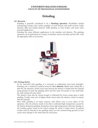
Grinding is generally considered to be a finishing operation. Possibilities include
resharpening cutting tools, surface grinding of work fixtures and mold sections, inside
diameter (ID) and outside diameter (OD) grinding of valve bodies, and many other
potential applications.
Grinding has many different applications in the machine tool industry. The grinding
operation can be performed on a variety of machines such as the lathe and the mill - with
the appropriate add-on accessories.
2.0 Cutting Action
To be successful with grinding, it is necessary to understand some basic principles.
Grinding uses a method of material removal called abrasion. Rather than cutting like a
lathe bit, the material is slowly worn away because the abrasive is harder than the material
being ground. In truth the grinding wheel acts like many thousands of very small lathe
bit, each cutting off some metal.
The abrasive must also be strong enough to withstand the forces acting upon it while
grinding. Usually some sort of impact shock occurs when the abrasive comes in contact
with the material.
Heat while grinding is of major concern, with effects seen at every phase of the
operation. Also the abrasive needs to be able to withstand high temperatures caused by
the friction during the grinding. Sometimes, these high temperatures will cause damage to
the bonding agents found in the wheel causing the wheel to break down. In general
coolant must be directed at the grinding wheel, not the material being ground, as heat
causes more damage to the wheel than the work piece.
MECHANICAL LAB 2_ GRINDING 1
2. UNIVERSITI MALAYSIA PAHANG
FACULTY OF MECHANICAL ENGINEERING
Most abrasive wheels need to be able to be resurfaced (dressed), as the old surface will
become impregnated with material during the grinding operation. Dressing is
accomplished with a diamond tipped tool.
3.0 Types of Grinding Machines
The grinder is a machine that is used for fine surface finishing and the amount of
material removed rarely exceeds a few thousands of an inch. These machines have been
developed over the years to satisfy specific needs of the industry it serves, so grinding has
become specialized, as has turning and milling. The most common types of grinders are
the surface grinder, the universal tool and cutter grinder, and the cylindrical
grinder.
MECHANICAL LAB 2_ GRINDING 2
3. UNIVERSITI MALAYSIA PAHANG
FACULTY OF MECHANICAL ENGINEERING
4.0 Surface Grinder
Surface grinding is probably the most fundamental of operations. Most shops have a
surface grinder even if they don't have a universal cutter grinder of a cylindrical grinder.
The basic machine has grinding wheel above the work area which can be fed downward
in very small increments into a work piece which is being moved to the left and the right
and in and out. This allows the wheel to contact all areas of the surface of the work piece.
The grinder is usually equipped with a magnetic plate used to hold the work piece. It is
sometimes referred to as a magnetic chuck, although it does not look anything like a
lathe chuck. The magnetic chuck holds magnetic materials only. However steel clamps (a
magnetic material) can be used to laterally clamp non-magnetic materials for surface
grinding.
MECHANICAL LAB 2_ GRINDING 3
4. UNIVERSITI MALAYSIA PAHANG
FACULTY OF MECHANICAL ENGINEERING
5.0 Surface Grinder Feeding and Coolant
The surface grinder demonstrated in this topic has a hydraulic feeding system (figure 5.1)
which actuates the table.
Figure 5.1
Left and right motion is governed by a set of dogs (figure 5.2) which can be set to limit
the feeding distance.
Figure 5.2
MECHANICAL LAB 2_ GRINDING 4
5. UNIVERSITI MALAYSIA PAHANG
FACULTY OF MECHANICAL ENGINEERING
Another set of dogs can be set to limit the in and out feeding distance (figure 5.3). The
speed and distance offset for each move is governed by a set of bleeder valves in the
hydraulic circuit (not shown)
Figure 5.3
Coolant for this grinder is fed, cleaned, cooled, and recirculated by a separate system
(figure 5.4).
Figure 5.4
MECHANICAL LAB 2_ GRINDING 5
6. UNIVERSITI MALAYSIA PAHANG
FACULTY OF MECHANICAL ENGINEERING
6.0 OD Cylindrical Grinding
The three most common types of cylindrical grinding processes are OD, ID, and
centerless.
OD (Outside Diameter) grinding is performed between centers. The work piece has
center drilled ends which accommodate center points and the work is rotated with a dog
which is driven off the grinder's face plate.
In the graphic above note the rotation of the work piece and the grinding wheel. With
OD grinding the work piece and the grinding wheel rotate in the same direction. This so
that the surface of the grinding wheel and the surface of the workpiece are moving in
opposite directions at the point of contact. This also reduces the possibility of ride-up or
jamming that can occur if they were rotating in opposite directions.
7.0 ID Cylindrical Grinding
ID (Inside Diameter) grinding is performed on tubular parts (with inside diameter) that
are usually held in a collet or chuck. The grinding wheel is smaller than the hole to be
ground and turns at very high speed to maintain the proper surface speed (compare the
large wheel and small work piece of OD grinding on previous page).
The image on the above shows a typical small hole being ground by an even smaller
mounted grinding wheel like one of those shown below
MECHANICAL LAB 2_ GRINDING 6
7. UNIVERSITI MALAYSIA PAHANG
FACULTY OF MECHANICAL ENGINEERING
As
with
OD
grinding the grinding wheel and the part need to be moving in opposite direction at the
point of contact. Therefore this ID part will turn clockwise and the ID wheel will turn
counterclockwise.
MECHANICAL LAB 2_ GRINDING 7
8. UNIVERSITI MALAYSIA PAHANG
FACULTY OF MECHANICAL ENGINEERING
8.0 Centerless
Centerless grinding is OD grinding performed on parts without centers and without
any place to hold on to it (as with a chuck). Picture the rollers in a roller bearing or a
dowel pin. There is nothing to hold on to.
On the centerless grinding machine the part actually rotates between a
grinding wheel and a regulation wheel. The regulating wheel governs the
rotation of the work piece. On many machines these types of parts are
being ground continuously by being fed in one end and ground out the
other end. It is vey fast.
MECHANICAL LAB 2_ GRINDING 8
9. UNIVERSITI MALAYSIA PAHANG
FACULTY OF MECHANICAL ENGINEERING
9.0 Universal Tool and Cutter Grinder
The universal tool and cutter grinder is used for almost any type of work required in the
tool room. This machine is most often used to re-sharpen the different types of cutting
tools found in the shop. It is not considered a very heavy-duty machine, so huge amounts
of material removal should not be attempted at this machine.
The machine is equipped with four main
components, the base, the wheel, the saddle and
the table.
There are many attachments used on the
universal cutter grinder. These attachments make
it possible to perform various types of
sharpening. The right and left tailback and
detachable motor make setups the most
challenging part of working in a tool room.
Tool grinding requires a very thorough
understanding of the geometry of the tool being
ground. The grinds found on each cutter are
complex, to say the least. Each grind has a
specific primary and secondary clearance angle
for the type of material being cut.
An efficient tool grinder will work far in advance
of the production curve, providing more than the required number of tools for each
production requirement, as a fail safe in case something should break. Coordination of
the tool room with the production team is critical.
Another important part of the universal cutter grinder is the type of grinding wheel that
the grinder chooses to use in the grinding work to be performed. As this subject is quite
detailed, it will be discussed in a different module of its own. (See Grinding Wheels).
MECHANICAL LAB 2_ GRINDING 9
10. UNIVERSITI MALAYSIA PAHANG
FACULTY OF MECHANICAL ENGINEERING
10.0 Bench Grinder
The bench grinder (figure 10.1) or is found in every shop It is used for rough work and
to grind tool bits made from high speed steel and carbide. Tool bit grinding is a
standard skill expected of all journeyman machinists. Drill sharpening attachments are
sometimes used on bench grinders (figure 10.2).
Figure 10.1 Figure 10.2
Some bench grinders have attachments for a special grinding processes like the wet
grinder. The wet grinding wheel turns very slowly through a bath of oil or water. This
type is suitable for blade sharpening. (figure 10.3)
Figure 10.3 Figure 10.4
Another special bench grinder is the cutter grinder used for more precise hand tool work.
Diamond face wheels are sometimes attached for harder materials like carbide and
ceramic. (figure 10.4)
MECHANICAL LAB 2_ GRINDING 10
11. UNIVERSITI MALAYSIA PAHANG
FACULTY OF MECHANICAL ENGINEERING
11.0 Lapping and Polishing
Lapping is the process of using a grinding compound of free grit and oil to create very
precise surfaces of high finish. Flat lapping machines are used to make small flat
surfaced parts (figure 11.1).
Figure 11.1
Polishing and
buffing are also
methods of
grinding. The
buffing compound
(grit) is applied to
buffing wheels
(figure 11.2) that
are mounted on
special buffing
grinders (figure
11.3)
Figure 11.2 Figure 11.3
MECHANICAL LAB 2_ GRINDING 11
12. UNIVERSITI MALAYSIA PAHANG
FACULTY OF MECHANICAL ENGINEERING
12.0 Grinding Wheels
Grinding wheels have a huge responsibility in the manufacturing industry. From
finishing parts to sharpening tools, grinding wheels are a common item found in all
machine shops. Grinding wheels can usually be classified as natural or artificial, such as
with a diamond wheel (natural) or a silicon carbide wheel (manufactured). This topic will
explain the difference.
Man has been using abrasives throughout history. The majority of natural abrasives,
such as sand, emery and quartz, have been replaced by manufactured abrasives such as
silicon carbide or aluminum oxide. Machinists use manufactured abrasives more often
than natural abrasives.
13.0 Grinding Wheels Material
There are two main material types for grinding wheels: Aluminum Oxide and Silicon
Carbide.
Aluminum Oxide is used to grind materials such as hard steel, wrought iron and
tough bronze. These materials are considered to have a high tensile strength.
Depending on the purity factor, it can also be used to grind cast iron as well as stellite,
which is used in dies and gages. Aluminum Oxide it the most common abrasive used in
grinding wheels.
Silicon carbide grinding wheels are used to grind low tensile strength materials, such
as aluminum, brass and softer bronzes. It is also used on most non-ferrous metals.
Other specialty materials are Cubic Boron Nitride, diamond, and gel ceramic abrasive.
MECHANICAL LAB 2_ GRINDING 12
13. UNIVERSITI MALAYSIA PAHANG
FACULTY OF MECHANICAL ENGINEERING
14.0 Grinding Wheels Shapes
Grinding wheels come in various shapes. Each shape is selected to perform a specific
job.
The cylindrical wheel is the most common type. Its cutting surface is located at the
periphery of the wheel. Wheels of this shape are often mounted on a plate.
The straight cup wheel is designed to cut on the periphery and the side face at the
same time. This type of wheel is often used to grind shoulders.
The dish wheel is a tool and cutter grinding wheel. It is typically used to regrind end
mills and has a specific shape to accomplish that.
The flared cup wheel is also tool and cutter grinding wheel. There are several cup
shapes available depending on the needs of the machinist.
Grinding wheels can be custom dressed with a diamond tool to achieve nearly any shape
desired.
MECHANICAL LAB 2_ GRINDING 13
14. UNIVERSITI MALAYSIA PAHANG
FACULTY OF MECHANICAL ENGINEERING
15.0 Grinding Wheels - How Abrasives Work
The function of abrasives is to remove material.
The wheel is made up of two components, the
abrasive and the bond.
The abrasive acts like the cutter and the bond is the
glue holding the abrasive grains together.
Since the abrasive is harder than the material being
ground, each grain acts like a cutting tool.
The size of the grain, like the size of any cutting tool,
is an important consideration.
16.0 Grinding Wheels Grain and Bond
There are six different ranges of grain, from very coarse to very fine. Grain sizes are
selected according to the type of finish desired, the material being ground, and the
amount of material being removed.
If the grinder is performing a roughing operation, a course grain would be selected,
providing maximum metal removal. Likewise, finer grains are used for minimum
material removal and high surface finish requirements.
The function of the bonding agent is to unite all of the abrasive grains into a wheel.
There are six types of bonding agents: vitrified, Profilometer, rubber, shellac, silicate
and metal. The vitrified type is used on most abrasives. In the resinoid bond, synthetic
resins are used to unite the grains of the abrasive. A resinoid bonded wheel produces a
higher surface finish, and should be run at a higher surface feet per minute than the
vitrified bond
17.0 Grinding Wheels Grade
The grade of the wheel describes the strength of the union between grain and bond.
It is desirable for the grains that have been worn down to break away, exposing new
grains to the work surface.
As this is accomplished, the old grains are released
from the wheel. The bond is rated hard grade if the
abrasive is released slowly, and the bond is difficult to
break. The grade is graded soft if the bond breaks away
easily, allowing rapid grain disintegration.
Selecting the proper grade for the wheel is one of the
more difficult choices to make in wheel selection.
It is important to remember that all abrasive grains are
hard, and that the hardness of the wheel refers to the
strength of the bond, not the hardness of the grain.
MECHANICAL LAB 2_ GRINDING 14
15. UNIVERSITI MALAYSIA PAHANG
FACULTY OF MECHANICAL ENGINEERING
18.0 Grinding Wheels Structure
Structure refers to the microscopic spaces between the abrasive grains and the bond.
If the spacing of the grains are close to each other, then the wheel is a densely
structured wheel. If the structure of the spacing is relatively wide, then the wheel has
an open structure. Open structure wheels have a greater ability to remove material
than dense wheels.
19.0 Grinding Wheels Identification
Each grinding wheel comes with a paper label glued to its face. The label provides much
information concerning the composition of the wheel.
MECHANICAL LAB 2_ GRINDING 15
16. UNIVERSITI MALAYSIA PAHANG
FACULTY OF MECHANICAL ENGINEERING
The system is a series of numbers and letters which codify the composition of the wheel.
The first letter indicates the type of abrasive used, using the letter A for Aluminum
Oxide or C for Silicon Carbide. Next the manufacturer of the wheel will indicate the
grain size, with appropriate numbers indicating a coarse, medium, or fine range. The
grade is indicated in alphabetical form, with the softest grade being the A end of the
alphabet, and the Z being the hardest.
Structure is indicated by a numerical rating, but its use is optional. Finally the bond type
is indicated by an abbreviation of the type of bond used, V for vitrified, S for silicate,
etc.
Wheels sometimes have different colors and can be representative of the type of wheel.
If the Norton Company is used as a reference, the following color codes would apply for
the best materials and processes for each wheel:
• White Aluminum Oxide - Used on tool
steels and mold steels
• Pink or Blue Aluminum Oxide - Used on
alloyed tool steels
• Off-White/Light Grey Monocrystalline
Aluminum Oxide - Better for holding than
the above, used on high speed steels as well
• Light Blue Synthetic Aluminum Oxide -
Works on all ferrous materials, used in high
production applications
• Gray Mixed Aluminum Oxide - Used on
centerless or cylindrical applications
• Green Silicon Carbide - Used on non-
ferrous materials such as aluminum and
carbide tooling.
MECHANICAL LAB 2_ GRINDING 16
17. UNIVERSITI MALAYSIA PAHANG
FACULTY OF MECHANICAL ENGINEERING
20.0 Grinding Wheels Safety
There are several safety issues that a machinist needs to be concerned with when dealing
with grinding wheels. Mainly, grinding wheels can crack. Most machines have safety
guards to deal with this problem, but keep in mind that a shattered wheel can injure the
machinist as well as the people working nearby. Various conditions can create this
problem such as excessive depth of cut, poorly balanced wheels, damaged wheels, or
improper assembly on the machine. It is best to keep grinding wheels stored in an area
that is dry and enclosed to avoid object or liquid contact with the wheels.
It is also a good idea to conduct a ring test on a grinding wheel prior to using it. A ring
test can locate an invisible crack. To perform this test let the inside diameter of the
wheel rest on one finger of your hand and then gently tap the wheel with the plastic
handle of a screw driver or wooden handle of a hammer. If you hear a clear metallic
ring, the wheel is probably in good shape. If the wheel is cracked the ring will be
somewhat dull and muffled
MECHANICAL LAB 2_ GRINDING 17