EXPERIMENT 2 : resistor colour codes and diodes
•Transferir como DOCX, PDF•
4 gostaram•26,515 visualizações


Recomendados
Mais conteúdo relacionado
Mais procurados
Mais procurados (20)
Semelhante a EXPERIMENT 2 : resistor colour codes and diodes
Semelhante a EXPERIMENT 2 : resistor colour codes and diodes (20)
Último
Último (20)
EXPERIMENT 2 : resistor colour codes and diodes
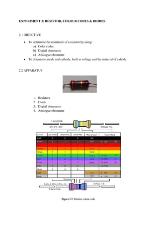
- 1. EXPERIMENT 2: RESISTOR, COLOUR CODES & DIODES 2.1 OBJECTIVE To determine the resistance of a resistor by using: a) Color codes b) Digital ohmmeter c) Analogue ohmmeter To determine anode and cathode, built in voltage and the material of a diode 2.2 APPARATUS 1. Resistors 2. Diode 3. Digital ohmmeter 4. Analogue ohmmeter
- 2. 2.3 PROCEDURES Part A: 1. variety of resistors with different color code is observed. 2. Resistor is taken, the color is determined to the suitable value by referring to the given scheme. 3. Central knob of digital ammeter is adjusted to get the appropriate measurement value. 4. The value of digital ammeter of resistor is recorded. 5. The central knob of analogue multimeter is adjusted to get the appropriate measurement value. 6. The value of analogue ammeter of resistor is recorded. 7. The above steps is repeated for other resistant. Part B: 1. A IN4001 and IN4002 diode is chosen. 2. The central knob of digital multimeter is adjusted to the symbol of diode. 3. The value of IN4001 diode is taken and recorded in table. 4. The measurement of a central knob analogue is taken. 5. The value of a IN4001 is measured by using analogue multimeter and recorded in table. 6. The anode and cathode is drew and labeled. 7. The above steps is repeated for IN4002. 2.4 ANALYSIS Table part A: Resistor Colour code DOM AOM (Ω) (Ω) (Ω)
- 3. Table part B: DIODE DOM AOM MATERIAL VIB (Ω) (Ω) IN4001 10.89 M 10.89 M 3 x IK 4 x 1K silica 0.585 IN4002 7.59 7.66 3.5 x 1K 4 x 1K silica 0.550 LED 1 28 x IK 28 x IK 1.827 LED 2 28 x 1K 28 x IK 1.827 Diode 6.1 x IK 6.1 x IK 0.742 orange Discussions: Diode is a device which functions to allow an electric current to pass in one direction or we called it the diode’s forward direction, while it also blocking current in the opposite direction which is the reverse direction. Built in voltage is the voltage across the depletion region in thermal equilibrium. From the experiment that has been conducted, first we use the multimeter to find the VIB of the diode. The purpose of finding the VIB is to determine the material of the diode. IN4001 and IN4002 diode have value of VIB approximate to 0.6V. Thus, from the theory and from what we have reffered in text book, 0.6V is the value of VIB for diode made of silica. For the LED 1, LED 2 and orange diode, it has value of 28k Ω and 6.1k Ω of VIB, which exceeded 0.6V which means they are made from something that is different from silica . For the resistance of the diode, for digital and analogue it showed different value. The different value of resistivity of the diode is because of different of voltage supply from both of the devices, analogue and digital multimeter. The connection of multimeter to anode and cathode of the diode must be correct so the current can flow fowardly, and as for LED it will light up. Wrong connection will not give any reading. Conclusion: As a conclusion, for the resistant the value resistant from analogue and digital reading of multimeter must be tally with the manual calculation from the codes of colour. For the diode it is important to check first the VIB of diode to know its material. The connection of anod and cathode also important to make sure the current to flow. References: http://pubs.acs.org/doi/abs/10.1021/jz300283h . built in voltage. <taken 15 oct 2012>
- 4. en.wikipedia.diode <taken 15 oct 2012>