KonnexSIM middleware
•
0 gostou•199 visualizações

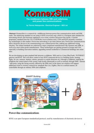
KonnexSIM the middleware between powerline communications stacks and mobile phones - used in residential automation and energy management

Recomendados
Recomendados
Mais conteúdo relacionado
Mais procurados
Mais procurados (20)
Destaque
Destaque (20)
Semelhante a KonnexSIM middleware
Semelhante a KonnexSIM middleware (20)
Mais de Yiannis Hatzopoulos
Mais de Yiannis Hatzopoulos (20)
Último
Último (20)
KonnexSIM middleware
- 1. KonnexSIMKonnexSIMThe middleware between SIM card cellphones and power line communications by Yiannis Hatzopoulos - Electrical Engineer – SES Ltd Abstract: KonnexSim is a connectivity middleware between power-line communication stacks and SIM cards. The underlying standard we are using is KNX (www.knx.org), which is a European open standard for networking electric and electronic appliances over wired, wireless and power-line media. A similar proprietary standard from the US is LONWorks (www.echelon.com). LON and KNX presently constitute key technologies in this market. Power-line networking is our main interest area. Power-line communications allow electronic devices to be communicating over a shared power-line, making any additional wiring obsolete. The related standards are endorsed by major component manufacturers like Siemens and ABB, as well as by most white-goods manufacturers. These technologies are gaining ground in Europe and USA, especially in building renovation markets, upgrading normal residential or commercial buildings into smart ones. We are developing an open standard link between a cellphone SIM card to a Linux BlueTooth / INTERNET gateway and KNX. This will allow control of any KNX connected device in a building (locks, heating, lights, air con, cameras, shutters, alarms, presence or smoke detectors etc.) through a cellphone; making the cellphone the control panel of the system, both locally (bluetooth) as well as remotely through SMS / internet / adsl ports; using the strong security offered by the SIM card. In the future our solution will support additional wired or wireless connectivity standards like Lon, ZigBee, Dect in a unified manner, all controllable through an ordinary SIM card cellphone. Power-line communications KNX is an open European standardized protocol, used by manufacturers of electronic devices to KonnexSIM 1
- 2. communicate information among their devices, using either twisted pair wires, RF frequency trans- mission or power-line communication. The latter is our project’s focus. In the due process, we have implemented a prototype residential gateway using a Eurotech ICE Vul- can Redhat Linux board, which receives commands from a SIM cellphone, either over the internet or through BlueTooth, passing them down to controlled devices over the power-line network. The power-line 220V base frequency of 50Hz is ‘loaded’ with control information, using FSK (Fre- quency Shift Keying) technology, in this case at 110KHz or 132 KHz. KNX uses CDMA/CA (Car- rier detect multiple access/collision avoidance) to multiplex the packet information flow across the network users. The main benefit for an installer of automation systems is that an existing set of cop- per wires is used both as power source and information conduit; and everything can be remotely controlled using an ordinary SIM cellphone. KNX PL110/PL132 Bus Access Unit and Gateway Our power-line bus was implemented using a prototype KNX PL110/PL132 device stack. The words ‘Network Stack’ indicate the ubiquitous OSI-7 network layer stack. Indeed, the KNX stand- ard specifies 5 out of the 7 OSI network layers, namely Physical, Data-link, Network, Transport and Application. KNX prescribes two power-line standards, PL110 and PL132. PL110 uses a base frequency of 110Khz and PL132 132Khz, either-way juxtaposed over the base 50Hz power-line frequency. KNX defines 2 additional stack sub-categories, the router stack and the bridge stack. Such devices can be bought directly from leading vendors such as Siemens and ABB, along with many standard devices like KNX controlled sensors or actuators, valves, lights, switches etc. , able to im- plement any imaginable type of building automation. The maximum control length in a KNX power-line net is around 600m. For the KNX signal to travel further, one needs to install a KNX bridge or a router. The reader should note that the KNX protocol is layer flexible. It allows the KNX developer to turn on/off stack layers down to the data link layer. Certain applications are expected to run very simple KNX network topology configurations, thus they need only the data link and physical layers to function properly. By disabling the overlaying stack segments, a stack implementation can be hos- ted in very cheap microprocessors (typically with 2 MHz clocks and just 8 K bytes of memory). When more complex network topologies are necessary, the application designer must deploy addi- tional layers, which support more complex net configurations, but need stronger micro-processors, both in terms of processing power and memory. Without going into too much detail, we must note that KNX presents certain analogies to TCP/IP in its packet structure. One can find in a typical KNX packet (or frame in KNX lingo) the network user’s source address, the packet’s destination address, the net domain address, error correction codes, packet counters, checksums (Frame check sequences) etc. The protocol is both unicast (one message reaches one recipient) and multicast (one message reaches multiple recipients concur- rently), to maximize the common channel bandwidth use. KNX prescribes very precise profiles for compatible devices, which can be categorized into 3 in- stallation modes: Auto, Easy and System. Auto is pretty similar to Plug-And-Play. Easy involves minimal user interaction (e.g. pressing a KonnexSIM 2
- 3. program button to connect a device to the net using a preselected address) and System, which in- volves advanced network configuration and administration using specialized software from KNX.org , similar to a complex TCP/IP network set-up, with router administration. The chips that we used to implement our KNX PL110/132 protocol, were Microchip's PIC P18F6720 micro controller and ST7538 power-line modem. Detailed specs on these ICs are avail- able at the respective manufacturers’ web sites. Prototyping was initially done using a cheap Mo- torola M68HC08 and ST7540. Their development specs are publicly distributed by Motorola and at- tached in my project files, to give an idea of a power-line stack's inner workings. The firmware inside each micro controller is used to generate and control the power-line signals that are communicated back and forth on the common power-line bus. The power-line modem does all the Digital Signal Processing necessary to filter out the incoming power-line noise. I will not go into much greater detail on the bus access unit, since one can procure similar RS232-to-KNX power-line Bus Access Units from several vendors. In either case, input to this module is received by an RS232 port, using a protocol prescribed by KXN as EMI (External Message Interface). This information is transcribed in 'power-line wave pulses' and is conduit over the power lines using a power-line modem chip, such as ST 7538, which executes the necessary digital signal processing and modulation. Power-lines constitute extremely noisy environments, thus sophisticated digital signal processing is necessary to transform information bits into frequency shifted waves on the power-net. The DSP process is presented bellow. On the receiving end, the process is reversed and the received commands are parsed and executed. My actual development prototype is depicted bellow. The blue box is a Linux embedded microcom- puter with 64 MBytes of flash memory (ARCOM Vulcan ICE), running a redhat variant of Linux. This is my KonnexSIM Gateway, which runs both a web service and BlueTooth I/O (a USB port is available on Vulcan). Connection of the Gateway to the power-line is executed by a serial connection (RS232 + custom made signal inverter) to my KNX power-line Bus Access Unit (PCB BAU – board marked as KNX BAU 1 in the picture). The commands sent over the power-lines are executed at the BAU2, which receives this informa- tion through the shared mains power-net. KonnexSIM 3
- 4. You can distinguish two chips on each BAU ( the insulation tape on the power supply of each BAU PCB exists for safety reasons from the high voltage). One chip is the PIC P18F6720 and the other ST7538. PIC has 128Kbyte of flash memory and 1Kbyte of EEPROM, necessary to run the serial communication parser and the full 5 OSI layer KNX stack; it generates bit messages for KNX packages with associated error correction codes, and controls the power-line modem wave pulses generated by ST 7538. The ST chip modulates this information overlaying the 50Hz power-line base frequency. The second board (mark as KNX BAU 2) receives this FSK modulated information from the shared power-line, applies error correction according the KNX protocol, and exports the information over its serial connection RS232 (or an I/O pin ) to a connected device. This completes the control loop, which can be reversed in direction from BAU2 to BAU1, since KNX is a half duplex communication tool. Thus, responses from the controlled devices can traverse the power-line and reach back to the gateway; from that point on through the internet, an SMS portal or Bluetooth, they reach the controlling cellphone. The programming of the firmware on the PIC chips was executed using MicroChip's MPLab and ICD2 Jtag unit. Linux boards similar to Vulcan retail at around 100 euros or less these days. Some technical details In our prototype project, the KonnexSIM gateway application resides inside Vulcan, which is a Redhat embedded Linux board, made by EuroTech (www.eurotech.co.uk). Vulcan runs an IBM J9 Java Virtual Machine 1.3.0. The application supports three I/O channels. One serial RS232 (Linux stty1), a proprietary bluetooth I/O, which is connected to the Linux board using a USB port, and KonnexSIM 4
- 5. Ethernet. An additional GSM modem can be connected to Vulcan as well. Special drivers were used to connect our java code both to the serial ports and the BlueTooth USB port on Vulcan. Vulcan is connected to the internet using a standard TCP/IP ADSL connection, which can be found in most residential and business areas nowadays. (PIC microprocessor and ST powerline modem schematic) Incoming commands to Vulcan may either be channelled over the internet, through an http request coming directly from the cellphone, or be received by an SMS to http portal from a KonnexSIM service provider's site (central KonnexSIM web server with GSM modem that services many subscribers, sending control commands to their gateways over the internet in response to SMS messages it receives). It depends whether KonnexSIM is running over a simple mobile STK, or has access to more advanced SIM hardware like a smartcard web server, which is still a novelty in mobile markets. The KonnexSIM software on Vulcan implements a miniature embedded web server, based on Nano-httpd – a 30Kbyte web open source project. This web server constitutes the main connection port to a cellphone, at all times the cellphone user is operating the KonnexSIM control device away from the building. This web service can also send SMS messages to the cellphone ( alarms, thresh-hold surpassed alerts etc.) using any external SMS web service portal. When the user is inside the building and in close proximity to Vulcan, he can simply opt to use Vulcan's BlueTooth port to dispatch commands and receive feedback from the system, without using GSM bandwidth. Additional BlueTooth-to-KNX hotspots can be placed in different areas of a building to increase the local command coverage area, creating a kind internal KonnexSIM control KonnexSIM 5
- 6. pico-cell. Concerning the communication flow, rudimentary XML/SOAP like scripts are communicated back and forth from the cellphone to the KonnexSIM Gateway. These scripts are formed as http requests or enveloped as SMS messages, according to the technology supported by the SIM card. These envelop all the command logic necessary to control our system remotely. The gateway receives these scripts, parses them, translates them into device specific commands, which are sent over the power-lines to receiving devices and executed. The devices upon execution return their status updates over the same power-line network. Status updates are collected by the Gateway, formed into XML/SOAP scripts which can be sent back to the cellphone. In case of emergencies, alert SMS messages are generated and sent to the cellphone, so the user can resort to immediate remedial actions. On the cellphone, a KonnexSIM midlet is hosted inside the SIM card. It contains a simplistic parser, that is used to parse and form commands destined at the KonnexSIM gateway. Note that a shared secret is utilized, with encrypted random challenges, attached inside XML/SOAP script fields. The Gateway which shares the mobile user's SIM card secret will only accept a submitted command if the random challenge is cleared OK – thus verified to be coming from a legitimate source. This feature adds a very significant layer of security on top of KNX, which is markedly weak in se- curity features. It should be noted that the KNX controllers at the device end-points (e.g alarms set- tings) could also be programmed to use point-to-point cryptographic challenges as an additional se- curity layer. Thus locks and switches could be engaged or disengaged only when the command is coming from the certified control source.The bottom line is that all connected devices in a building can be controlled both locally and remotely using the power-line connectivity as an ad-hoc com- puter network. The cellphone can become a cheap control panel to the system, adding not only con- venience but also security, which is important. The gateway concept allows us to extend the proto- cols used into a wide variety of wired and wireless standards, incorporating legacy and new pro- tocol technologies, while still retaining a standard and consistent XML/SOAP interface to a mobile device, becoming a true communication middleware. Commercial aspects Automation control in buildings delivers significant advantages. Without going into too much de- tail, I should note that coordinated control is an extremely effective way of fine-tuning the energy profile of a building. The applications on energy management in commercial buildings can be con- stituted as follows ● Peak demand monitoring ● Current overconsumption detection ● Power network monitoring ● Imposed load shedding at peak times ● Metering and billing control support ● Energy pulse counting ● Data Logging ● Energy pattern visualisation KonnexSIM 6
- 7. Residential remote control increases the safety and comfort factor, allowing immediate reaction in cases of emergencies. In the case of residential settings, similar applications can be ● Central lighting control inside the house and garden. ● Choice of different lighting scenarios or individual dimming. ● Control of blinds and shutters with regards to wind, brightness and rain. ● Control of blinds and shutters on a time schedule. ● Automatic and optimized heating control according to room usage or the needs of the inhab- itants. ● The ventilation and air-conditioning can react to the presence of people in the room. ● Remote control of music can be achieved from everywhere within the house. ● Remote control can be made available for every single room. ● Easy visualisation and integration of audio-systems and monitoring cameras. ● Reporting of open or broken windows and doors, burglary, smoke emission etc. ● Camera monitoring of the entrance. ● Deterrence of potential break-ins by switching on the entire home lighting system (panic mode). ● Simulation of an occupied home through smart control of lighting and blinds (break -in de- terrent) KonnexSIM 7
- 8. All these functions can be remotely controlled by a standard cellphone. Current improvements in electronic design and production methods have brought the cost of introducing smart technologies in a new building to around 3-4% of its total construction budget. This sum can be recovered due to enhanced power savings throughout the building's life; moreover in many countries, tax breaks and norms are being introduced as an incentive to improve the environmental footprint of buildings. With energy prices going up, Smart building technologies are becoming ever more attractive op- tions. This is especially true for low cost after-market smart control products, which can be in- stalled into existing buildings without making any alternation to them. This is where KonnexSIM fits-in. It is a low cost aftermarket residential control unit, coming with its own mobile interface; which will allow you to control any potential connected device from both a remote setting (internet) as well as a local setting (BlueTooth). KonnexSIM will offer the same de- gree of control flexibility to a power-line network that a TV remote control has offered to TV view- ing, both within the premises of a building as well as across the globe when travelling. All the leading white goods manufacturers are coming up with new designs that are equipped with new hardware port control interfaces. Some of them use proprietary ports, while most follow stand- ards. Proprietary solutions allow service integrators to develop and market interfaces to common standards. It is by no accident that major manufacturers are committing significant research resources into smart building technologies. Also do not fail to notice that in an ageing society – building automa- tion is becoming a quite tempting solution to improve the well-being and safety of the elderly. Lowering costs indicate the wave of the future, which is inevitable. In our case, we became involved in designing power-line communication boards and a Linux resid- ential gateway, following a subcontracting agreement by one of the world leaders in white-goods manufacturing. The subsequent availability of a mobile control portal was indispensable to the ef- fectiveness of our solution. It is the most cost effective approach to provide users with a low cost re- mote control panel, both inside their home as well as from across the globe. The SIM platform is ideal to this task, due to its security, its enormous base and universal mobile handset compatibility. Marketing KonnexSIM and its mobile portal will not be separated from marketing a wholly new line of KNX/Lon compatible devices. I would like to thank the Simagine sponsors for supporting the prototyping of KonnexSIM. Yiannis Hatzopoulos Electrical Engineer KonnexSIM 8