
Recomendados
Mais conteúdo relacionado
Mais procurados
Mais procurados (20)
Semelhante a Paper
Semelhante a Paper (20)
Mais de Veluppillai Mohan
Paper
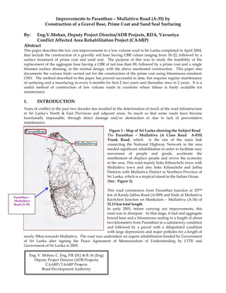
- 1. Improvements to Paranthan – Mullaitivu Road (A-35) by Construction of a Gravel Base, Prime Coat and Sand Seal Surfacing By: Eng.V.Mohan, Deputy Project Director/ADB Projects, RDA, Vavuniya Conflict Affected Area Rehabilitation Project (CAARP) Abstract This paper describes the low cost improvements to a low volume road in Sri Lanka completed in April 2004, that include the construction of a gravelly soil base having CBR values ranging from 18-22, followed by a surface treatment of prime coat and sand seal. The purpose of this was to study the feasibility of the replacement of the aggregate base having a CBR of not less than 80, followed by a prime coat and a single bitumen surface dressing, in the normal design, with the above mentioned construction. This paper also documents the various trials carried out for the construction of the prime coat using bituminous emulsion CSS1. The method described in this paper has proved successful to date, but requires regular maintenance of surfacing and a resurfacing in every 6 months for first 2 two years and thereafter once in 2 years. It is a useful method of construction of low volume roads in countries where labour is freely available for maintenance. 1. INTRODUCTION Years of conflict in the past two decades has resulted in the deterioration of much of the road infrastructure in Sri Lanka‟s North & East Provinces and adjacent areas. So much so that some roads have become functionally impassable, through direct damage and/or destruction or due to lack of preventative maintenance. Figure 1 - Map of Sri Lanka showing the Subject Road The Paranthan – Mullaitivu (A Class Road A-035) Trunk Road, which is the one of the main link connecting the National Highway Network in the area needed significant rehabilitation in order to facilitate easy movement of people and goods, accelerate the resettlement of displace people and revive the economy in the area. This road mainly links Kilinochchi town with Mullaitivu town and also links Kilinochchi and Jaffna Districts with Mullaitivu District in Northern Province of Sri Lanka, which is a tropical island in the Indian Ocean (See. Figure 1). This road commences from Paranthan Junction at 257th km of Kandy-Jaffna Road (A-009) and Ends at Mullaitivu Kachcheri Junction on Mankulam – Mullaitivu (A-34) of 52.13 km total length. In early 2003, before carrying out improvements, this road was in disrepair. At that stage, it had and aggregate bound base and a bituminous sealing to a length of about two kilometers from Paranthan in a satisfactory condition and followed by a paved with a dilapidated condition with large depressions and major potholes for a length of nearly 50km towards Mullaitivu. The road was undertaken an urgent rehabilitation funded by Government of Sri Lanka after signing the Peace Agreement of Memorandum of Understanding by LTTE and Government of Sri Lanka in 2003. Eng. V. Mohan, C. Eng, FIE (SL) & B. Sc (Eng) Deputy Project Director (ADB Projects) CAARP/TAARP Projects Road Development Authority Paranthan – Mullaittivu Road (A 35)
- 2. The subject road is situated in the dry zone of the Island where the annual rainfall is less than 1500mm. The ambient temperature of the area where this road is situated varies from 25 to 350C. The existing pavement in the whole section consisted of double layers of 50mm single sized aggregate with extremely large patches without aggregate. The formation width of road was 6 to 8m available, whilst the carriageway width of 4 to 5 m was just sufficient for the passage of one vehicle. Due to these poor and dilapidated conditions, the road users were compelled to take other longer detours to avoid this road. The rehabilitation & improvements to Paranthan – Mullaitivu Road were entrusted to Road Development Authority (RDA), by the Ministry of Highways, Sri Lanka and the works commenced in June 2003. Since there were no contractual system and the construction industry was not developed in the area, at that time there were not even a single capable road work experience contractors were available. Therefore Chief Engineer/Mullaitivu of the RDA had to undertake and execute these rehabilitation & improvements through a RDA direct Labour system. A field laboratory was set up and attached with Chief Engineer‟s office by the Research & Development Division, Ratmalana at Kilinochchi to enhance the this project in order to assure the quality control techniques at the site to carry out investigations for scientific design, material survey, testing for selection of materials for construction and quality control and research work during construction. 2. INVESTIGATIONS, DESIGNS AND IMPROVEMENTS TO ROAD The method of design adopted at site is as given in the “A Guide to the structural design of Bitumen – surfaced roads in Tropical & Sub-Tropical Countries” published by Transport Road Research Laboratory, UK Road Note 31(1977). There are three main steps to be followed in designing a new road pavement. These are: a) estimating the amount of traffic (and its axle load distribution) that will use the road over the selected design life, b) assessing the strength of the sub grade & Sub-base soil over which the road is to be built, c) Taking into account a) and b), selecting the most economical combination of pavement materials and layer thickness that will be sufficient to provide satisfactory service over the design life of the pavement with only routine maintenance. The sub-grade CBR value and the cumulative number of standard axles expected to be carried out by the pavement during its design life having been determined the required pavement thickness can be obtained from the design. The steps to be taken in designing road strengthening measures on the basis of deflection beam surveys are indicated in Fig. 2. The first stage is to decide the design life required of the strengthened pavement, taking into account the traffic predictions and economic considerations.
- 3. Fig. 2 THE ROAD STRENGTHENING PROCEDURE The estimated traffic on this road in 2004 after construction was about 500 vehicles per day. The design life of the pavement was chosen as 10 years. For pavement design, the axel load traffic was estimated to be about 0.1 million standard axles for a design life of 10 years at a growth rate of 4% from the traffic pattern developed in Sri Lanka. Therefore as the California Bearing Ratio (CBR) value of sub grade normally varied from 3 to 8, a design of a sub base of thickness varying from 150 to 300mm, a dense aggregate base of 150mm thickness with a 4 day soaked CBR of more than 80 followed by a prime coat and a Single bitumen surface dressing (SBST) was to be adopted for this project. The works on this road was commenced at Paranthan end at a chain age of 2.0+ 000.0 km and continued towards Mullaitivu end at chain age 52.0 +300 km. At this stage, it was realized that it very difficult to be completed within the stipulated time period of 18 months and the limited financial resources (Rs. 50.0 million), if this design was adapted and continued throughout this project. Therefore, another alternative & an appropriate design was considered by taking into consideration of economy & sustainability and to make use of the available resources of large quantities of gravelly soils with 4 day soaked CBR values ranging from 19-22, that were considered suitable as replacement materials for the base for the expected low volume of traffic. The test results from the research lab for the Engineering properties of the available soils from the following gravel borrow pits are given in the following Table No.1 The improvements to this road for the chain ages 2.0 to 52.13 km from Paranthan to Mullaitivu comprised flood level for a 10 year cycle for some sections of the road, after providing adequate surface and cross- Drainage structures by means of side drains, culverts and lead away drains: and building the amended pavement structure including a gravelly soil sub base of 150 mm to 300 mm thickness followed by a gravelly soil base of thickness 150mm, applying a prime coat and a sand seal. Lab ID Mark Particle Size Analysis LL PL PI OMC MAX DD CBR(%) 50 mm 37.5 mm 28 mm 40 mm 14 mm 10 mm 15 mm 2.36 1.18 600 300 150 75 S/21 Kalliyady-1 - - 100 99 97 95 84 68 46 36 28 19 16 40 22 18 11.8 1.96 17 S/12 Vaddakachchi 100 97 92 82 65 51 35 30 24 19 12 8 6 33 14 18 10.2 2.01 19 S/15 Kalliyady-2 - - - 100 82 59 36 30 23 19 15 11 9 37 19 18 11.2 1.98 21 S/16 Kokavil - - 100 100 90 76 58 49 40 32 24 16 14 39 22 17 15.0 1.93 22 Traffic predictions Decide design Life of the strengthened pavement Economic considerations Analysis Deflection data Determine design deflection level Design overlay Base reconstruction and drainage works if needed Construct overlay Deflection survey and classification of Surface Condition Deflection criterion curve for intended overlay
- 4. 3. SOILS FOR CONSTRUCTION According to the material survey conducted by the R&D Division, four number of suitable soil borrow pits were identified by carrying out tests from the RDA lab for their physical Engineering properties given in Table No.1. Materials used for sub-bases & Bases confirmed the requirements of sub-section 1708.2 of SSCM of Roads & Bridges. Soils having dry densities not less than 1600 kg/m3 were used on the top 150mm of the embankment fills and below that soil having dry densities not less than 1500kg/m3. Gravelly soils having a 4 day soaked CBR value not less than 20, liquid limit of not more than 50 and plasticity index of not more than 25 and gravelly soils with 4 day soaked CBR value not less than 25, liquid limit of not more than 50, plasticity index between 6 and 25 were used for the construction of sub bases and Gravelly Soil Bases (GSB) respectively. 4. STEPS OF CONSTRUCTION FOR SECTION WITH AMENDED PAVEMENT STRUCTURE The following appropriate steps of construction were carried out at this site for the section from chain ages 2.00 to 52.13 km on Paranthan-Mullaitivu Road from the Paranthan end:- 4.1 The construction of sub-base commenced in any section of the works after drainage works completed. 4.2 Prior to spreading of sub-base materials, the sub-grade prepared in conformity with the section 304 of SSCM and cleared of any extraneous mater, and surface suitably moistened and before placing sub-base materials, existing paved road, the bituminous crust removed by scarifying and existing surface suitably compacted. Table No.1 Soils Engineering Properties 4.3 Wherever necessary, the road formation was widened to a minimum width of 7.0 m and raised to the required levels. This was done by removing the loose sand and gravel on existing unpaved road, grass and loose soil on shoulders, verges and side slopes of embankments, benching the side slopes and road foundations and compaction layers of suitable soils of compacted thickness of 150mm to the required densities as given in section 3. 4.4 In sections where no widening or raising was done, the top 150mm layer of existing soil was compacted to 100% standard density. 4.5 Over the compacted sub- grade to the full width of carriageway, a sub-base of thickness 150 to 300mm in layers of 75 to 150mm compacted thickness was constructed with gravelly soil having the characteristics as given in section 3 compacted to 100% standard density.. 4.6 Over the compacted sub- base to the full width of the road formation, a Gravel Soil Base of thickness 150mm was constructed with soil having the characteristics as given in section 3 compacted to 100% standard density. 4.7 Over the compacted base to the width of carriageway of 5.0m, a prime coat and a sand seal were applied. The details of this work are given under section 5. Photograph No.1 Soil Base Spreading Photograph No.2: Soil base Consolidation
- 5. 5. CONSTRUCTION OF PRIME COAT AND SURFACE DRESSING (SAND SEALS) INCLUDING TRIALS 5.1 Prime Coat A prime coat is an application of low viscosity asphalt to a granular base in preparation for an asphalt surface course. The prime coat is designed to perform several functions: - To coat and bond lose mineral particles on the surface of the base. - To harden or toughen the surface. - To waterproof the surface of the base. - To plug capillary voids. - To provide adhesion between the base and the next course. In order for the prime to satisfy these criteria it needs to penetrate very little into the base course. Most primes in the past have been some type of cut back. The use of emulsified asphalt for this purpose is relatively new. Special precautions are very necessary when emulsion is used, in asphalt emulsion tiny particles of asphalt cement are suspended in water. To be effective, these small particles of asphalt must be able to penetrate the surface voids of the granular base. If the surface voids are too small they will serve. Initially the GSB was shaped and compacted to the correct longitudinal and transverse profile. The compaction was done with standard 8 tones vibrating and 8-10 tone smooth wheeled rollers. After shaping and compaction, and dust and loose materials on the surface well brushed and were removed. Then the gravel surface was lightly sprinkled with water to moisture the surface. The bituminous material was then sprayed uniformly over the gravel surface. The materials that was used for the priming was cationic slow setting bitumen emulsion CSS-1 conforming to ASTM 2397-79 mixed with an equal amount of water. The rates of application of the diluted emulsion were 1.0- 1.5 l/m2. The spraying was done at the ambient Temperature not below 15 º C by using a 4000 l bitumen distributor. The sprayed surface was now kept closed for traffic for about 24-48 hours during which time most of the penetration of the bituminous material into the GSB surface took place. Ideally the priming material was expected to penetrate about 3-6mm into the gravel surface and dried to a matt finish during this period. After the lapse of this period the surface was uniformly blinded with coarse sand as blotting material confirmed with sub section 1704.4 of SSCM. Light rolling of the surface was now optional and facilitated the embedment of the blinding material onto the bituminous surface, thus making the bituminous crust thicker. At this stage, as slow moving light traffic could also be beneficial, the road was opened for pneumatic tired traffic whenever the speed could be controlled. Whenever uncontrolled traffic has to be allowed earlier, this was done after blinding the surface with the lapse of at least 3 hours from the completion of priming. However cart traffic was not allowed for about 3 days until the surface hardened. Photograph No.3&4: Priming over base surface Table 02: Type and rate of application of binder for prime coat. Section of The Road Type of Prime Coat Rate of application of binder l/m2 2.00 – 52.12 CSS-1 diluted with 1:1 water 1.0-1.5
- 6. 5.2 Surface Dressing (Sand Sealing) A Traditional Sri Lanka periodic maintenance technique which effectively SEALS the road surface but does not improve its skid resistance. How ever Sri Lankan climatic is suitable for good surface dressing or sand seals with long, dry periods and generally predictable rainfall season. Comparatively these low traffic intensities are other advantages. A sand seal comprise a thin film of „binder generally bitumen or tar, which is sprayed on to the primed road surface and then covered with a layer of coarse sand and rolling using a pneumatic tired roller. The thin film of binder acts as a water proofing seal and prevents the entry of surface water into the road structure. Sand seal may fulfill any of the following functions:- 1. Provide a water proof seal to a road surface, then preventing the ingress of surface water to the lower of a road pavement. 2. Arrest the deterioration of an existing road surface that is showing signs of distress. 3. Restore the skid resistance to an existing road surface. 4. Provide a dust-free and durable running surface for a previously untreated mechanically stable road base. Sand seal is, therefore, a very important maintenance technique which is capable of greating extending the life of an existing sound road pavement, if the process is undertaken at the optimum time. A sand seal was constructed on the primed gravel surface after a lapse of about 3-4 days from the time of priming. This increased the useful life of the road. The primed surface was dried, and any loose material swept and removed from the surface. Then cationic rapid setting bitumen emulsion CRS-1 applied at the ambient temperature not below 15 º C conforming to STM D-2377-79 and sub-section 1702.3 of SSCM was sprayed at the rate of 0.75-1.0 l/m2, immediately covered with sand confirm to the sub-section 1701.5 of SSCM at the rate of 8m3/1000m2 and rolled with a heavy standard 9 wheeled pneumatic tired roller. Table 03: Type and rate of application of binder for Sand Seals. Section of The Road Type of Prime Coat Rate of application of binder l/m2 2.00 – 52.12 CRS-1 0.75 -1.0 The sand seal was carried out by CRS-1 on the entire trial sections as given in section 5.2. The entire sections of prime coat carried out by CSS-1. 6. MAINTENANCE OF ROAD Within a few weeks it was observed that several small patches of surface treatment throughout the road got peeled off. These were corrected manually by the application of a coat of CRS-1 emulsion and blinding with sand. Potholes forming on the primed surface were immediately attended to by patching. This was done by filling the potholes with similar gravel to that used for the existing GSB, compacting with a hand tamper, re priming and then sand sealing the patches manually. For proper maintenance of road, the drainage facilities were regularly maintained. The verges and the side drains were made to function properly so that rain water falling onto the road found its way quickly onto the side drains.
- 7. 7. PRESENT STATE OF ROAD The work that commenced in June 2003 was successfully completed by April 2004. At present, 3 years after construction with proper maintenance, this road is behaving satisfactorily. 8. CONCLUDING REMARKS As this section of road has performed satisfactorily from April 2004 to date and Sand Sealing attended in every six months after completion for first two years, it can be concluded that this method has saved the cost & time difference between the constructions of a 150mm thick crushed aggregate base and a gravel base of the same thickness. However it required a resurfacing of a sand seal in every 6 months for first 2 two years and thereafter once in 2 years. This method is low cost and has proved successful to date, but requires regular maintenance of surfacing. It is a useful method of construction of low volume roads in countries where labour is freely available for maintenance. References. 1. Standard Specifications for Construction and Maintenance of Roads & Bridges (1989) – SSCM. 2. Surface Dressing Treatment – Graham often 3. A guide for the Structural design of bitumen – Surfaced roads in tropical and Sub-tropical countries – Road Note. 31 – 1977. (TRRL – Department of Environment & Transport)