SlideShare uma empresa Scribd logo
1 de 25
Case Study:NJM2309 Application Circuit Design (PWM Step-down Converter) All Rights Reserved Copyright (C) Bee Technologies Corporation 2011 1
Contents Design Specification NJM2309 Typical Application Circuit Averaged Buck Switch Model Buck Regulator Design Workflow Setting PWM Controller’s Parameters. Programming Output Voltage: Rupper, Rlower Inductor Selection: L Capacitor Selection: C, ESR Stabilizing the Converter Load Transient Response Simulation ,[object Object],Appendix Type 2 Compensation Calculation using Excel Feedback Loop Compensators Simulation Index All Rights Reserved Copyright (C) Bee Technologies Corporation 2011 2
Design Specification Step-Down (Buck) Converter : ,[object Object]
VIN, MIN = 6 (V)
VOUT = 3.3 (V)
VOUT, Ripple = 1% ( 33mVP-P )
IOUT, MAX = 1.0 (A)
IOUT, MIN = 0.2 (A)Control IC : ,[object Object]
Switching Frequency – fosc = 105 (kHz)All Rights Reserved Copyright (C) Bee Technologies Corporation 2011 3 NJM2309 Datasheet
NJM2309 Typical Application Circuit All Rights Reserved Copyright (C) Bee Technologies Corporation 2011 4 Power Switches Filter & Load PWM Controller  Schematic is captured from NJM2309 datasheet page  4.
All Rights Reserved Copyright (C) Bee Technologies Corporation 2011 5 TASK: Design and Evaluation of the Circuit  3? 2? 1 4? 5? NJM2309 Typical Application Circuit
Buck Regulator Design Workflow  All Rights Reserved Copyright (C) Bee Technologies Corporation 2011 6 Setting PWM Controller’s Parameters: VREF, VP 1 Setting Output Voltage: Rupper, Rlower 2 Inductor Selection: L 3 Capacitor Selection: C, ESR 4 Stabilizing the Converter: R2, C1, C2 ,[object Object]
Step2: Set C1=1kF, C2=1fF, (always keep the default value) and R2= calculated value (Rupper//Rlower) as the initial values.
Step3: Select a crossover frequency (about 10kHz or fc < fosc/4). Then complete the table.
Step4: Read the Gain and Phase value at the crossover frequency (10kHz) from the Bode plot, Then put the values to the table
Step5: Select the phase margin at the fc ( > 45 ). Then change the K value until it gives the satisfied phase margin, for this example K=6 is chosen for Phase margin = 46.
Remark: If K-factor fail to gives the satisfied phase margin, Increase the output capacitor C then try Step1 to Step5 again.5 Load Transient Response Simulation 6
Buck Regulator Design Workflow  All Rights Reserved Copyright (C) Bee Technologies Corporation 2011 7 3 4 5 2 1
[object Object]
VP=2.5 (vFBH and vFBLare not provided, the default value is used).Setting PWM Controller’s Parameters All Rights Reserved Copyright (C) Bee Technologies Corporation 2011 8 1 ,[object Object],[object Object]
Inductor Selection: L All Rights Reserved Copyright (C) Bee Technologies Corporation 2011 10 Inductor Value from Given:  VI,max = 40(V), VOUT = 3.3(V) IOUT,min = 0.2(A) RL,min = (VOUT /IOUT,min ) = 16.5() fosc = 105(kHz) Then: LCCM 72.1(uH),  ,[object Object],3
Capacitor Selection: C, ESR (NJM2309) All Rights Reserved Copyright (C) Bee Technologies Corporation 2011 11 Capacitor Value From and Given: VI, max = 40 V VOUT = 3.3 V, VOUT, Ripple = 1% ( 33mVP-P ) L (H)  = 100 IOUT, MAX = 1(A), IL, Ripple = 0.25(A) Then: ,[object Object],In addition: ,[object Object],4
Stabilizing the Converter  (NJM2309) All Rights Reserved Copyright (C) Bee Technologies Corporation 2011 12 5 Specification: VOUT = 3.3V VIN = 6 ~ 32V ILOAD = 0.2 ~ 1A PWM Controller: VREF = 0.52V VP = 2.5V fOSC = 105kHz Rlower = 1k, Rupper = 5.346k, L = 100uH,  C = 1000uF (ESR = 132m) Task: ,[object Object],G(s) 1 e.g. Given values from National Semiconductor Corp. IC: LM2575  2 3 4
All Rights Reserved Copyright (C) Bee Technologies Corporation 2011 13 Stabilizing the Converter  (NJM2309) 5 The element of the Type 2 compensator ( R2, C1, and C2 ), that stabilize the converter, can be extracted by using Type 2 Compensator Calculator (Excel sheet) and open-loop simulation with the Average Switch Models (ac models). Step2 Set C1=1kF, C2=1fF, and R2=calculated value (Rupper//Rlower) as the initial values. Step1 Open the loop with LoL=1kH and CoL=1kF then inject an AC signal to generate Bode plot.  C1=1kF is AC shorted, and C2 1fF is AC opened (or Error-Amp without compensator).
Stabilizing the Converter  (NJM2309) All Rights Reserved Copyright (C) Bee Technologies Corporation 2011 14 5 Step3 Select a crossover frequency (about 10kHz or fc < fosc/4 ), for this example, 10kHz is selected. Then complete the table. values from  2 Calculated value of the Rupper//Rlower values from  1

Mais conteúdo relacionado

Mais procurados

Knee-Point Voltage Determination for Current Transformer Functional Identific...
Knee-Point Voltage Determination for Current Transformer Functional Identific...Knee-Point Voltage Determination for Current Transformer Functional Identific...
Knee-Point Voltage Determination for Current Transformer Functional Identific...
IJERD Editor
 
Electrical maintenance fundamentals
Electrical maintenance fundamentalsElectrical maintenance fundamentals
Electrical maintenance fundamentals
James Shearer
 

Mais procurados (20)

Current Transformer and Potential Transformer
Current Transformer and Potential TransformerCurrent Transformer and Potential Transformer
Current Transformer and Potential Transformer
 
Ppt of current transformer
Ppt of current transformerPpt of current transformer
Ppt of current transformer
 
Dead time elimination for voltage source inverter
Dead time elimination for voltage source inverterDead time elimination for voltage source inverter
Dead time elimination for voltage source inverter
 
Overcurrent protection
Overcurrent protectionOvercurrent protection
Overcurrent protection
 
Document org
Document orgDocument org
Document org
 
Inverter topologies
Inverter topologiesInverter topologies
Inverter topologies
 
3 phase current source inverter
3 phase  current  source  inverter3 phase  current  source  inverter
3 phase current source inverter
 
Unit-III Waveform Generator
Unit-III Waveform GeneratorUnit-III Waveform Generator
Unit-III Waveform Generator
 
Knee-Point Voltage Determination for Current Transformer Functional Identific...
Knee-Point Voltage Determination for Current Transformer Functional Identific...Knee-Point Voltage Determination for Current Transformer Functional Identific...
Knee-Point Voltage Determination for Current Transformer Functional Identific...
 
INVERTERS PRESENTATION
INVERTERS PRESENTATIONINVERTERS PRESENTATION
INVERTERS PRESENTATION
 
Testing of Transformer (AREVA)
Testing of Transformer (AREVA)Testing of Transformer (AREVA)
Testing of Transformer (AREVA)
 
SOLAR POWERED THREE PHASE MOTOR FOR VARIOUS APPLICATION
SOLAR POWERED THREE PHASE MOTOR FOR VARIOUS APPLICATIONSOLAR POWERED THREE PHASE MOTOR FOR VARIOUS APPLICATION
SOLAR POWERED THREE PHASE MOTOR FOR VARIOUS APPLICATION
 
Harmonic comparisons of various PWM techniques for basic MLI
Harmonic comparisons of various PWM techniques for basic MLIHarmonic comparisons of various PWM techniques for basic MLI
Harmonic comparisons of various PWM techniques for basic MLI
 
Inverters (DC-AC)
Inverters (DC-AC)Inverters (DC-AC)
Inverters (DC-AC)
 
How to conduct the lightning impulse withstand test on 550kv GIS?
How to conduct the lightning impulse withstand test on 550kv GIS?How to conduct the lightning impulse withstand test on 550kv GIS?
How to conduct the lightning impulse withstand test on 550kv GIS?
 
Chapter 16
Chapter 16Chapter 16
Chapter 16
 
ELECTRICAL POWER SYSTEM - II. symmetrical three phase faults. PREPARED BY : J...
ELECTRICAL POWER SYSTEM - II. symmetrical three phase faults. PREPARED BY : J...ELECTRICAL POWER SYSTEM - II. symmetrical three phase faults. PREPARED BY : J...
ELECTRICAL POWER SYSTEM - II. symmetrical three phase faults. PREPARED BY : J...
 
Percentage Impedance of Transformer
Percentage Impedance of TransformerPercentage Impedance of Transformer
Percentage Impedance of Transformer
 
Electrical maintenance fundamentals
Electrical maintenance fundamentalsElectrical maintenance fundamentals
Electrical maintenance fundamentals
 
TESTING AND COMMISSIONING OF ELECTRICAL EQUIPMENTS. TESTING OF CURRENT TRANSF...
TESTING AND COMMISSIONING OF ELECTRICAL EQUIPMENTS. TESTING OF CURRENT TRANSF...TESTING AND COMMISSIONING OF ELECTRICAL EQUIPMENTS. TESTING OF CURRENT TRANSF...
TESTING AND COMMISSIONING OF ELECTRICAL EQUIPMENTS. TESTING OF CURRENT TRANSF...
 

Semelhante a PWM Step-down Converter(NJM2309)

EE452_Flyback Convert
EE452_Flyback ConvertEE452_Flyback Convert
EE452_Flyback Convert
ki hei chan
 
Small signal analysis based closed loop control of buck converter
Small signal analysis based closed loop control of buck converterSmall signal analysis based closed loop control of buck converter
Small signal analysis based closed loop control of buck converter
Ramaraochowdary Kantipudi
 
Assignment 1 Description Marks out of Wtg() Due date .docx
Assignment 1  Description Marks out of Wtg() Due date .docxAssignment 1  Description Marks out of Wtg() Due date .docx
Assignment 1 Description Marks out of Wtg() Due date .docx
fredharris32
 
Design and implementation of cyclo converter for high frequency applications
Design and implementation of cyclo converter for high frequency applicationsDesign and implementation of cyclo converter for high frequency applications
Design and implementation of cyclo converter for high frequency applications
cuashok07
 
Flyback Converter using PWM IC(LTspice Version)
Flyback Converter using PWM IC(LTspice Version)Flyback Converter using PWM IC(LTspice Version)
Flyback Converter using PWM IC(LTspice Version)
Tsuyoshi Horigome
 
H2PToday1201_design_IR
H2PToday1201_design_IRH2PToday1201_design_IR
H2PToday1201_design_IR
Parviz Parto
 

Semelhante a PWM Step-down Converter(NJM2309) (20)

PWM Buck Converter using Average Model
PWM Buck Converter using Average ModelPWM Buck Converter using Average Model
PWM Buck Converter using Average Model
 
「SPICEの活用方法」セミナー資料(28JAN2011) PPT
「SPICEの活用方法」セミナー資料(28JAN2011) PPT「SPICEの活用方法」セミナー資料(28JAN2011) PPT
「SPICEの活用方法」セミナー資料(28JAN2011) PPT
 
PSpiceで位相余裕度シミュレーション
PSpiceで位相余裕度シミュレーション PSpiceで位相余裕度シミュレーション
PSpiceで位相余裕度シミュレーション
 
EE452_Flyback Convert
EE452_Flyback ConvertEE452_Flyback Convert
EE452_Flyback Convert
 
Spiceを活用した電源回路シミュレーションセミナーテキスト 18 feb2015
Spiceを活用した電源回路シミュレーションセミナーテキスト 18 feb2015Spiceを活用した電源回路シミュレーションセミナーテキスト 18 feb2015
Spiceを活用した電源回路シミュレーションセミナーテキスト 18 feb2015
 
Small signal analysis based closed loop control of buck converter
Small signal analysis based closed loop control of buck converterSmall signal analysis based closed loop control of buck converter
Small signal analysis based closed loop control of buck converter
 
Critical Conduction Mode (CRM) PFC Circuit
Critical Conduction Mode (CRM) PFC CircuitCritical Conduction Mode (CRM) PFC Circuit
Critical Conduction Mode (CRM) PFC Circuit
 
電流臨界モード方式PFC制御回路の解説書
電流臨界モード方式PFC制御回路の解説書電流臨界モード方式PFC制御回路の解説書
電流臨界モード方式PFC制御回路の解説書
 
Assignment 1 Description Marks out of Wtg() Due date .docx
Assignment 1  Description Marks out of Wtg() Due date .docxAssignment 1  Description Marks out of Wtg() Due date .docx
Assignment 1 Description Marks out of Wtg() Due date .docx
 
Design and implementation of cyclo converter for high frequency applications
Design and implementation of cyclo converter for high frequency applicationsDesign and implementation of cyclo converter for high frequency applications
Design and implementation of cyclo converter for high frequency applications
 
Flyback Converter using PWM IC(LTspice Version)
Flyback Converter using PWM IC(LTspice Version)Flyback Converter using PWM IC(LTspice Version)
Flyback Converter using PWM IC(LTspice Version)
 
15 47-58
15 47-5815 47-58
15 47-58
 
Critical Conduction Mode (CRM) PFC Circuit
Critical Conduction Mode (CRM) PFC CircuitCritical Conduction Mode (CRM) PFC Circuit
Critical Conduction Mode (CRM) PFC Circuit
 
Small Signal Modelling and Controller Design of Boost Converter using MATLAB
Small Signal Modelling and Controller Design of Boost Converter using MATLABSmall Signal Modelling and Controller Design of Boost Converter using MATLAB
Small Signal Modelling and Controller Design of Boost Converter using MATLAB
 
Buck converter design
Buck converter designBuck converter design
Buck converter design
 
H2PToday1201_design_IR
H2PToday1201_design_IRH2PToday1201_design_IR
H2PToday1201_design_IR
 
Time response of first order systems and second order systems
Time response of first order systems and second order systemsTime response of first order systems and second order systems
Time response of first order systems and second order systems
 
PPT FINAL (1)-1 (1).ppt
PPT FINAL (1)-1 (1).pptPPT FINAL (1)-1 (1).ppt
PPT FINAL (1)-1 (1).ppt
 
Chapter 08
Chapter 08Chapter 08
Chapter 08
 
Final Project
Final ProjectFinal Project
Final Project
 

Mais de Tsuyoshi Horigome

Mais de Tsuyoshi Horigome (20)

FedExで書類を送付する場合の設定について(オンライン受付にて登録する場合について)
FedExで書類を送付する場合の設定について(オンライン受付にて登録する場合について)FedExで書類を送付する場合の設定について(オンライン受付にて登録する場合について)
FedExで書類を送付する場合の設定について(オンライン受付にて登録する場合について)
 
Update 46 models(Solar Cell) in SPICE PARK(MAY2024)
Update 46 models(Solar Cell) in SPICE PARK(MAY2024)Update 46 models(Solar Cell) in SPICE PARK(MAY2024)
Update 46 models(Solar Cell) in SPICE PARK(MAY2024)
 
SPICE PARK APR2024 ( 6,793 SPICE Models )
SPICE PARK APR2024 ( 6,793 SPICE Models )SPICE PARK APR2024 ( 6,793 SPICE Models )
SPICE PARK APR2024 ( 6,793 SPICE Models )
 
Update 22 models(Schottky Rectifier ) in SPICE PARK(APR2024)
Update 22 models(Schottky Rectifier ) in SPICE PARK(APR2024)Update 22 models(Schottky Rectifier ) in SPICE PARK(APR2024)
Update 22 models(Schottky Rectifier ) in SPICE PARK(APR2024)
 
SPICE PARK APR2024 ( 6,747 SPICE Models )
SPICE PARK APR2024 ( 6,747 SPICE Models )SPICE PARK APR2024 ( 6,747 SPICE Models )
SPICE PARK APR2024 ( 6,747 SPICE Models )
 
Update 31 models(Diode/General ) in SPICE PARK(MAR2024)
Update 31 models(Diode/General ) in SPICE PARK(MAR2024)Update 31 models(Diode/General ) in SPICE PARK(MAR2024)
Update 31 models(Diode/General ) in SPICE PARK(MAR2024)
 
SPICE PARK MAR2024 ( 6,725 SPICE Models )
SPICE PARK MAR2024 ( 6,725 SPICE Models )SPICE PARK MAR2024 ( 6,725 SPICE Models )
SPICE PARK MAR2024 ( 6,725 SPICE Models )
 
Update 29 models(Solar cell) in SPICE PARK(FEB2024)
Update 29 models(Solar cell) in SPICE PARK(FEB2024)Update 29 models(Solar cell) in SPICE PARK(FEB2024)
Update 29 models(Solar cell) in SPICE PARK(FEB2024)
 
SPICE PARK FEB2024 ( 6,694 SPICE Models )
SPICE PARK FEB2024 ( 6,694 SPICE Models )SPICE PARK FEB2024 ( 6,694 SPICE Models )
SPICE PARK FEB2024 ( 6,694 SPICE Models )
 
Circuit simulation using LTspice(Case study)
Circuit simulation using LTspice(Case study)Circuit simulation using LTspice(Case study)
Circuit simulation using LTspice(Case study)
 
Mindmap of Semiconductor sales business(15FEB2024)
Mindmap of Semiconductor sales business(15FEB2024)Mindmap of Semiconductor sales business(15FEB2024)
Mindmap of Semiconductor sales business(15FEB2024)
 
2-STAGE COCKCROFT-WALTON [SCHEMATIC] using LTspice
2-STAGE COCKCROFT-WALTON [SCHEMATIC] using LTspice2-STAGE COCKCROFT-WALTON [SCHEMATIC] using LTspice
2-STAGE COCKCROFT-WALTON [SCHEMATIC] using LTspice
 
PSpice simulation of power supply for TI is Error
PSpice simulation of power supply  for TI is ErrorPSpice simulation of power supply  for TI is Error
PSpice simulation of power supply for TI is Error
 
IGBT Simulation of Results from Rgext or Rgint
IGBT Simulation of Results from Rgext or RgintIGBT Simulation of Results from Rgext or Rgint
IGBT Simulation of Results from Rgext or Rgint
 
Electronic component sales method centered on alternative proposals
Electronic component sales method centered on alternative proposalsElectronic component sales method centered on alternative proposals
Electronic component sales method centered on alternative proposals
 
Electronic component sales method focused on new hires
Electronic component sales method focused on new hiresElectronic component sales method focused on new hires
Electronic component sales method focused on new hires
 
Mindmap(electronics parts sales visions)
Mindmap(electronics parts sales visions)Mindmap(electronics parts sales visions)
Mindmap(electronics parts sales visions)
 
Chat GPTによる伝達関数の導出
Chat GPTによる伝達関数の導出Chat GPTによる伝達関数の導出
Chat GPTによる伝達関数の導出
 
伝達関数の理解(Chatgpt)
伝達関数の理解(Chatgpt)伝達関数の理解(Chatgpt)
伝達関数の理解(Chatgpt)
 
DXセミナー(2024年1月17日開催)のメモ
DXセミナー(2024年1月17日開催)のメモDXセミナー(2024年1月17日開催)のメモ
DXセミナー(2024年1月17日開催)のメモ
 

Último

Último (20)

Partners Life - Insurer Innovation Award 2024
Partners Life - Insurer Innovation Award 2024Partners Life - Insurer Innovation Award 2024
Partners Life - Insurer Innovation Award 2024
 
A Year of the Servo Reboot: Where Are We Now?
A Year of the Servo Reboot: Where Are We Now?A Year of the Servo Reboot: Where Are We Now?
A Year of the Servo Reboot: Where Are We Now?
 
Apidays Singapore 2024 - Building Digital Trust in a Digital Economy by Veron...
Apidays Singapore 2024 - Building Digital Trust in a Digital Economy by Veron...Apidays Singapore 2024 - Building Digital Trust in a Digital Economy by Veron...
Apidays Singapore 2024 - Building Digital Trust in a Digital Economy by Veron...
 
presentation ICT roal in 21st century education
presentation ICT roal in 21st century educationpresentation ICT roal in 21st century education
presentation ICT roal in 21st century education
 
Data Cloud, More than a CDP by Matt Robison
Data Cloud, More than a CDP by Matt RobisonData Cloud, More than a CDP by Matt Robison
Data Cloud, More than a CDP by Matt Robison
 
Boost PC performance: How more available memory can improve productivity
Boost PC performance: How more available memory can improve productivityBoost PC performance: How more available memory can improve productivity
Boost PC performance: How more available memory can improve productivity
 
Polkadot JAM Slides - Token2049 - By Dr. Gavin Wood
Polkadot JAM Slides - Token2049 - By Dr. Gavin WoodPolkadot JAM Slides - Token2049 - By Dr. Gavin Wood
Polkadot JAM Slides - Token2049 - By Dr. Gavin Wood
 
Powerful Google developer tools for immediate impact! (2023-24 C)
Powerful Google developer tools for immediate impact! (2023-24 C)Powerful Google developer tools for immediate impact! (2023-24 C)
Powerful Google developer tools for immediate impact! (2023-24 C)
 
Understanding Discord NSFW Servers A Guide for Responsible Users.pdf
Understanding Discord NSFW Servers A Guide for Responsible Users.pdfUnderstanding Discord NSFW Servers A Guide for Responsible Users.pdf
Understanding Discord NSFW Servers A Guide for Responsible Users.pdf
 
Manulife - Insurer Innovation Award 2024
Manulife - Insurer Innovation Award 2024Manulife - Insurer Innovation Award 2024
Manulife - Insurer Innovation Award 2024
 
Real Time Object Detection Using Open CV
Real Time Object Detection Using Open CVReal Time Object Detection Using Open CV
Real Time Object Detection Using Open CV
 
Top 5 Benefits OF Using Muvi Live Paywall For Live Streams
Top 5 Benefits OF Using Muvi Live Paywall For Live StreamsTop 5 Benefits OF Using Muvi Live Paywall For Live Streams
Top 5 Benefits OF Using Muvi Live Paywall For Live Streams
 
Artificial Intelligence Chap.5 : Uncertainty
Artificial Intelligence Chap.5 : UncertaintyArtificial Intelligence Chap.5 : Uncertainty
Artificial Intelligence Chap.5 : Uncertainty
 
Scaling API-first – The story of a global engineering organization
Scaling API-first – The story of a global engineering organizationScaling API-first – The story of a global engineering organization
Scaling API-first – The story of a global engineering organization
 
GenAI Risks & Security Meetup 01052024.pdf
GenAI Risks & Security Meetup 01052024.pdfGenAI Risks & Security Meetup 01052024.pdf
GenAI Risks & Security Meetup 01052024.pdf
 
ProductAnonymous-April2024-WinProductDiscovery-MelissaKlemke
ProductAnonymous-April2024-WinProductDiscovery-MelissaKlemkeProductAnonymous-April2024-WinProductDiscovery-MelissaKlemke
ProductAnonymous-April2024-WinProductDiscovery-MelissaKlemke
 
Workshop - Best of Both Worlds_ Combine KG and Vector search for enhanced R...
Workshop - Best of Both Worlds_ Combine  KG and Vector search for  enhanced R...Workshop - Best of Both Worlds_ Combine  KG and Vector search for  enhanced R...
Workshop - Best of Both Worlds_ Combine KG and Vector search for enhanced R...
 
🐬 The future of MySQL is Postgres 🐘
🐬  The future of MySQL is Postgres   🐘🐬  The future of MySQL is Postgres   🐘
🐬 The future of MySQL is Postgres 🐘
 
AWS Community Day CPH - Three problems of Terraform
AWS Community Day CPH - Three problems of TerraformAWS Community Day CPH - Three problems of Terraform
AWS Community Day CPH - Three problems of Terraform
 
Axa Assurance Maroc - Insurer Innovation Award 2024
Axa Assurance Maroc - Insurer Innovation Award 2024Axa Assurance Maroc - Insurer Innovation Award 2024
Axa Assurance Maroc - Insurer Innovation Award 2024
 

PWM Step-down Converter(NJM2309)

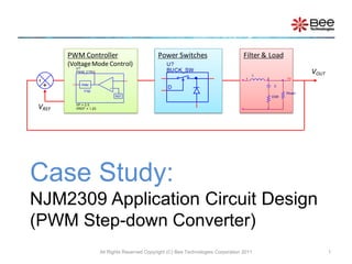
  • 1. Case Study:NJM2309 Application Circuit Design (PWM Step-down Converter) All Rights Reserved Copyright (C) Bee Technologies Corporation 2011 1
  • 2.
  • 3.
  • 4. VIN, MIN = 6 (V)
  • 6. VOUT, Ripple = 1% ( 33mVP-P )
  • 7. IOUT, MAX = 1.0 (A)
  • 8.
  • 9. Switching Frequency – fosc = 105 (kHz)All Rights Reserved Copyright (C) Bee Technologies Corporation 2011 3 NJM2309 Datasheet
  • 10. NJM2309 Typical Application Circuit All Rights Reserved Copyright (C) Bee Technologies Corporation 2011 4 Power Switches Filter & Load PWM Controller  Schematic is captured from NJM2309 datasheet page 4.
  • 11. All Rights Reserved Copyright (C) Bee Technologies Corporation 2011 5 TASK: Design and Evaluation of the Circuit 3? 2? 1 4? 5? NJM2309 Typical Application Circuit
  • 12.
  • 13. Step2: Set C1=1kF, C2=1fF, (always keep the default value) and R2= calculated value (Rupper//Rlower) as the initial values.
  • 14. Step3: Select a crossover frequency (about 10kHz or fc < fosc/4). Then complete the table.
  • 15. Step4: Read the Gain and Phase value at the crossover frequency (10kHz) from the Bode plot, Then put the values to the table
  • 16. Step5: Select the phase margin at the fc ( > 45 ). Then change the K value until it gives the satisfied phase margin, for this example K=6 is chosen for Phase margin = 46.
  • 17. Remark: If K-factor fail to gives the satisfied phase margin, Increase the output capacitor C then try Step1 to Step5 again.5 Load Transient Response Simulation 6
  • 18. Buck Regulator Design Workflow All Rights Reserved Copyright (C) Bee Technologies Corporation 2011 7 3 4 5 2 1
  • 19.
  • 20.
  • 21.
  • 22.
  • 23.
  • 24. All Rights Reserved Copyright (C) Bee Technologies Corporation 2011 13 Stabilizing the Converter (NJM2309) 5 The element of the Type 2 compensator ( R2, C1, and C2 ), that stabilize the converter, can be extracted by using Type 2 Compensator Calculator (Excel sheet) and open-loop simulation with the Average Switch Models (ac models). Step2 Set C1=1kF, C2=1fF, and R2=calculated value (Rupper//Rlower) as the initial values. Step1 Open the loop with LoL=1kH and CoL=1kF then inject an AC signal to generate Bode plot.  C1=1kF is AC shorted, and C2 1fF is AC opened (or Error-Amp without compensator).
  • 25. Stabilizing the Converter (NJM2309) All Rights Reserved Copyright (C) Bee Technologies Corporation 2011 14 5 Step3 Select a crossover frequency (about 10kHz or fc < fosc/4 ), for this example, 10kHz is selected. Then complete the table. values from 2 Calculated value of the Rupper//Rlower values from 1
  • 26. All Rights Reserved Copyright (C) Bee Technologies Corporation 2011 15 Stabilizing the Converter (NJM2309) 5 Gain: T(s) = H(s)GPWM Step4 Read the Gain and Phase value at the crossover frequency(10kHz) from the Bode plot, Then put the values to the table. Phase  atfc Tip: To bring cursor to the fc = 10kHz type “ sfxv(10k) ” in Search Command. Cursor Search
  • 27. Stabilizing the Converter (NJM2309) All Rights Reserved Copyright (C) Bee Technologies Corporation 2011 16 5 Step5 Select the phase margin at fc (> 45 ). Then change the K value (start from K=2) until it gives the satisfied phase margin, for this example K=3 is chosen for Phase margin = 48. As the result; R2, C1, and C2 are calculated. Remark: If K-factor fail to gives the satisfied phase margin, Increase the output capacitor C then try Step1 to Step5 again.  K Factor enable the circuit designer to choose a loop cross-over frequency and phase margin, and then determine the necessary component values to achieve these results. A very big K value (e.g. K > 100) acts like no compensator (C1 is shorted and C2 is opened).
  • 28.
  • 30. C2=97.07pF.*Analysis directives: .AC DEC 100 0.1 10MEG
  • 31. All Rights Reserved Copyright (C) Bee Technologies Corporation 2011 18 Stabilizing the Converter (NJM2309) 5 Gain and Phase responses after stabilizing Gain: T(s) = H(s) G(s)GPWM Phase  atfc Phase margin = 48.801 at the cross-over frequency - fc = 9.237kHz. Tip: To bring cursor to the cross-over point (gain = 0dB) type “ sfle(0) ” in Search Command. Cursor Search
  • 32. Load Transient Response Simulation All Rights Reserved Copyright (C) Bee Technologies Corporation 2011 19 The converter, that have been stabilized, are connected with step-load to perform load transient response simulation. 3 4 5 3.3V/16.5 = 0.2A step to 0.2+0.8=1.0A load 2 *Analysis directives: .TRAN 0 20ms 0 1u 1
  • 33.
  • 34.
  • 35. A. Type 2 Compensation Calculation using Excel All Rights Reserved Copyright (C) Bee Technologies Corporation 2011 23
  • 36. All Rights Reserved Copyright (C) Bee Technologies Corporation 2011 24 B. Feedback Loop Compensators Type1 Compensator Type2 Compensator Type2a Compensator Type2b Compensator Type3 Compensator
  • 37.