What Are The Drone Anti-jamming Systems Technology?
Ia
1. May 20, 2011
IB Physics HL Year 1
Tomohiro Urakami
Introduction
During this investigation, an air rocket was launched vertically on launcher
with different amount of pressure inside. The motion of first few seconds of rocket
launching was recorded by 600FPS high-speed camera. The purpose of this investigation
was to find the alteration of air rocket’s maximum forcein different values of pressure.
The research question of this investigation is “How does the pressure inside air rocket
affect the maximum force of the rocket after launched.”
In Pressure’s law, pressure is defined as the force applied per unit area. In the
equation, this is defined as,
P= (1.1)
where F is force and A is the area.This equation could then reformed into the new
equation,
P= (1.2)
where m is the mass and a is acceleration. From the logger pro, the acceleration of the
rocket could be calculated. By substituting value of acceleration and the mass of a rocket,
a relationship between the force and the pressure of the rocket could be
researched.Therefore, confining that the area of the rocket is the same for all trials, it
could be stated that pressure of the rocket and the maximum force of the rocket are in
direct linear proportional relationship.
Design
R.Q: How does the pressure inside an air rocket affect the maximum force of the rocket?
Independent Variables: the independent variable during this investigation was the
pressure inside an air rocket, which was a 2L Coke water bottle. There were six different
values of pressure used and four trials were done for each pressure. The pressure was
inserted into the air rocket by the air pumper for bicycle wheels. Pressure were
measuredand changed by the manometer that was attached to the pumper.
Dependent Variable: The dependent variable was the acceleration of an air rocket. The
2. May 20, 2011
IB Physics HL Year 1
Tomohiro Urakami
motion of air rocket launching was recorded by 600FPS high-speed camera. This video
was inserted into logger pro on computer and the acceleration was calculated by the slope
of v-t graph. According to this value, the maximum force of the air rocket was calculated
by substituting the number of acceleration and the mass of the rocket into the equation, “F
=m*a”.
Controlled Factors:
The first controlled factor was the air rocket itself. This is because as shown in
the equation in introduction, the mass and the area of the air rocket affects the value of
acceleration of air rocket and thus these had to be controlled in order to find the
relationship between pressure and the acceleration of air rocket.
The second controlled factor was the launcher. Although there were some same
types of launchers, the structures of those launchers are not exactly the same.The
diameter of pipe could be different and the friction of the pipe when rocket flies into air
could be different as well. Therefore, it was necessary to keep the shape of air rocket the
same in order to find accurate data.
The third controlled factor was the angle of the launching. The launcher was
stabilized on the ground so that the rocket would launch vertically. This was controlled
because angle would change the gravitational force applied to the rocket and thus the
value of acceleration could be affected.
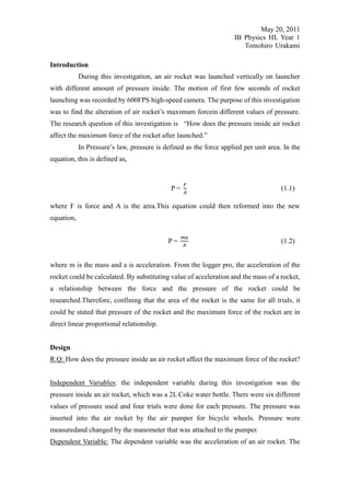
Figure 1: Set Up
3. May 20, 2011
IB Physics HL Year 1
Tomohiro Urakami
Ruler As Scalar
Water Bottle Air Rocket
The Pipe Inserts Air
Launching Lock
Launch Pad
Procedure
As shown in Figure 1, this investigation was done outside. Ruler was used as
scalar so that during the process of analyzing video, acceleration of the rocket could be
found. Rocket was connected to the pipe shown in the diagram. Before launching rocket,
air was inserted inside rocket by the pumper of bicycle wheels so that the pressure inside
rocket increases. The rocket was launched from the launch pad as the launching lock is
unlocked. The rocket was flown into the air and the motion of rocket flying out of pipe
was recorded by 600FPS high-speed camera. This experiment was done in 6 different
value of pressure in kPa and 4 trials were done for each pressure value.
4. May 20, 2011
IB Physics HL Year 1
Tomohiro Urakami
Data and Processing
Length of the rocket: 0.3 m
Mass of the rocket: 55.38 g
Figure 2: Data Table of Acceleration in Different Pressure
Force (J)
±6
Pressure Trial 1 Trial 2 Trial 3 Trial 4 Average Uncertainty
(kPa
)
68.9 36.44 34.81 36.21 38.03 36 4
137.9 49.09 48.08 47.64 49.06 48 4
206.8 90.60 90.38 87.83 90.38 90 6
275.8 95.25 95.14 93.20 95.25 95 4
344.7 126.04 120.89 125.21 126.21 125 5
413.7 146.81 146.98 145.59 144.98 146 4
Figure 2 is the table of collected data during this investigation. As Figure 1 shows, the
value of acceleration increases as the pressure inserted into rocket increases. The small
value of uncertainty shows that the data collected during this research were accurate.This
data table was used in order to find the maximum force or the rocket at each trial in
Figutre 3.
Figure 3: Data Table of Maximum Force in Different Pressure
Acceleration
(m/s/s)±50
Pressure Trial 1 Trial 2 Trial 3 Trial 4 Average Uncertainty
(kPa)
68.9 658.0 628.5 653.8 686.8 660 26.00
137.9 886.5 868.2 860.2 885.8 880 13.00
206.8 1636.0 1632.0 1586.0 1632.0 1620 25.00
275.8 1720.0 1718.0 1683.0 1720.0 1710 19.00
344.7 2276.0 2183.0 2261.0 2279.0 2250 48.00
413.7 2651.0 2654.0 2629.0 2618.0 2640 18.00
5. May 20, 2011
IB Physics HL Year 1
Tomohiro Urakami
Figure 3 is the data table with the value of maximum force in each trial in different value
of pressure. There is an increase in the value of force as the pressure increases. According
to this data table, a final graph of Maximum Force versus Pressure Graph was created.
The uncertainty bar was set to be 50 for maximum force, which is about 2% off for the
rocket launch with 413.7kPa. This is a relatively small number, and it increases the level
of confidence.
Figure 4: Final Graph
Figure 4 is the final graph that gives the answer for the research question. The graph
shows that the maximum force increases and the pressure inside the air rocket increases.
The constant value of slope m is “0.326x”.
6. May 20, 2011
IB Physics HL Year 1
Tomohiro Urakami
Figure 5: Final Graph with High and Low Fits
Figure 5 is the final graph with high and low fits which indicates the level of confidence
of the data in this investigation. Although three dots are not in the range of high and low
fits, all dots are close to the fits and the uncertainty bars of those dots are reaching either
high or low fits. This shows that data collected is accurate enough to answer the research
question.
Sample Calculation
Finding Uncertainty for Acceleration
(Biggest acceleration-smallest acceleration)/2
(686.8 m/s/s – 628.5m/s/s)/2 = 26
Changing into kPa from PSI
1Pa = 145.04×10⁻⁶Psi
10PSI/ 145.04×10−6 = 68.9kPa
7. May 20, 2011
IB Physics HL Year 1
Tomohiro Urakami
Finding Maximum Force for Each Trial
F = (mass of the rocket) * (acceleration of a trial)
= 0.05538kg * 658m/s/s
= 36.44J
Finding Uncertainty for Maximum Force
{(Biggest a+50)*(0.05538+0.00003kg)-(Smallest a-50)*(0.05538-0.00003kg)}/2
{(686.8+50)*(0.05541kg)-(628.5-50)*(0.05535kg)
= 26
Figure 6: Sample Video
Figure 6 is one of the scenes of the video, which was analyzed. In this figure, there are
many blue dots, which show the path of rocket as it left the launch pad. Those blue dots
were used in order to make graph.
8. May 20, 2011
IB Physics HL Year 1
Tomohiro Urakami
Figure 7: Sample Graph
This is one of the graphs recorded by the high-speed camera during this investigation.
The slope was found from a dot where exactly the rocket leaves the edge of the pipe. The
acceleration was found by finding the slope of this graph. The x-axis Time in this graph
had to be divided by 20 in order to find the time in 600FPS, which was used to record the
motion of rocket in high-speed. This value of edited time was also applied to the y-axis,
the velocity of the rocket. The value of acceleration is negative because as Figure 6 shows,
the rocket moves to left in the video. Going direction of left is considered negative and
this is why the value of acceleration is negative in the graph. However, the actual value is
supposed to be in positive and thus when data was transferred into data table, those
negative turned into positive.
9. May 20, 2011
IB Physics HL Year 1
Tomohiro Urakami
Conclusion
According to the data collected and calculated in data and processing column,
the final equation given was,
F = (0.326 0.03 J/kPa)P+(11.4 J) (4.1)
where F is the force and P is pressure in kPa. The equation above shows the linear direct
proportional relationship between the maximum force and the pressure. As more pressure
is inserted into a rocket, a rocket will have faster acceleration, which eventually increases
the maximum force of the rocket. It was calculated that the constant increase of force per
1kPa is 0.326X. This equation supports the hypothesis stated in introduction.
Figure 2 is the collection of original data collected during this investigation.
The uncertainties for each pressure show that the difference among 4 trials of launching
was small enough to be stated that the data was recorded accurately. Furthermore, the
uncertainty of the slope of final graph Figure 4 is 0.03K/kPa, which is about 9% off. Since
this uncertainty value is relatively small, it increases the level of confidence in terms of
the data collection. The y-intercept of this graph is supposed to show the value of
maximum force when the rocket is at rest, which is supposed to be 0. The y intercept is
11.4, which is relatively a small off. As a result, the relatively small value of uncertainty
and the accuracy of the slope of the final graph indicate the high level of confidence of the
result in this research.
This research could be repeated in different circumstances. Different type of
water bottle could be used as rocket in this research. In this case, same as this
investigation, only one rocket should be used in order to keep the mass and the shape of
the rocket same. Also, water could be inserted inside the rocket and use water rocket in
order to record data of acceleration of the rocket. In this case, the amount of the water
inside rocket needs to be controlled so that the mass of the rocket stays the same in each
trial. Also, different angle could be used for this investigation. However, since the
gravitational force that applies to the rocket would change in different angle, the angle
needs to be controlled in order to find the relationship between the maximum force of the
rocket and the pressure inside it.
Evaluation
10. May 20, 2011
IB Physics HL Year 1
Tomohiro Urakami
Although the hypothesis was supported, there are some possible errors made
during this research. Those errors need to be improved in next research.
The first possible error was that the rocket launcher was not stabilized on the
ground. Thus, when the rocket was launched, the rocket did not launch in the same
direction in all trials. This could cause some error in the value of acceleration because of
the lost in the momentum due to the non-stabilized launcher base. Therefore, the rocket
launcher needs to be stabilized in order to launch the rocket in the same direction.
The second possible error was the pressure inside the rocket. Although the
pressure put inside the rocket was measured by the manometer attached to the pump,
some pressure could have gone out of the rocket when the needle was unplugged.
However, this is inevitable since when the needle is unplugged, space is createdwhere the
air inside the rocket could escape. Thus, in order to avoid a big amount of pressure going
out of the rocket, the needle must be unplugged as fast as possible.
The third possible error made during this investigation was the shape of the
water bottle used. During this investigation, only one water bottle was used to keep the
mass the same. The water bottle was added pressure in each trial and hit hard on the
ground after it flew into air. This could cause the damage to the bottle and could have
changed its shape, which could affect the value recorded during the investigation.
Therefore, experimenters must make sure that they catch the rocket after each launch so
that big damage will not apply to the rocket.
Consequently, if this investigation was to be repeated in the same circumstance,
those three errors need to be improved in order to eliminate possible errors and collect as
accurate data as possible.