Pumps are widely used in process plants to transfer fluid from one point to the other and the Process Engineer is often required to specify the correct size of pumps that will optimize system performance. Though pump sizing can easily be performed using software such as Pipe-Flo®, understanding the basic principle will not only aid one to better interpret the results obtained by pump sizing software but also to better design pumps. Centrifugal pump sizing overview is presented in this tutorial.
2. Telema Harry, Provisional Lic (Eng.), PMP®, MSc
Fig. 2: Components of a centrifugal pump (Fantagu, 2008)
Pump Head
Head is simply the height or elevation measured in feet
(meter) a pump can raise a fluid. The higher the head the
greater the pump power. Understanding head is very
important for the maintenance engineers or operators
working in plants. Operators in chemical plants
generally work with pressure which is a function of fluid
density (i.e. P = ρgh) and they will want to know the
system pressure at every point in time. However, pump
manufacturers use head as one of the criteria for pump
selection. Unlike pressure that changes with fluid
density, the head is constant irrespective of the fluid
density.
The pump head is the measure of the net work
performed on the fluid.
General Energy Equation
This is an adaptation of the popular Bernoulli’s equation
to account for energy losses in the system.
𝑝1
γ
+ 𝑧1 +
𝑣1
2
2𝑔
+ ℎ 𝐴 − ℎ 𝑅 − ℎ 𝐿 =
𝑝2
γ
+
𝑧2 +
𝑣2
2
2𝑔
…………………………….. (1a)
ℎ 𝐴 = (
𝑝2−𝑝1
𝛾
) + (𝑧2 − 𝑧1) + (
𝑣2
2−𝑣1
2
2𝑔
) + ℎ 𝐿 + ℎ 𝑅 .(1b)
Where:
γ = specific weight, γ = ρg
𝑝
γ
= pressure head - 𝑯 𝑷
𝑧 = elevation head or static head- 𝑯 𝑺
𝑣2
2𝑔
= velocity head - 𝑯 𝒗
ℎ 𝐴 = energy added by the motor or a prime mover. It is
also called the TOTAL DYNAMIC HEAD or TOTAL
SYSTEM HEAD by some pump manufacturers (Mott &
Untener, 2015; Head, 1996).
ℎ 𝑅 = energy removed from the fluid by a mechanical
device
ℎ 𝐿 = minor energy losses due to friction on the pipe,
valve, elbows and fittings
Friction Head 𝑯𝒍
The friction head expressed in feet (ft) or meter (m) is
the energy loss in the system due to resistance to flow
between the fluid and the internal walls of the piping
system as the fluid flows along the pipe.
Over the years, several methods have been proposed to
calculate the frictional loss in pipes. Two popular
methods are discussed below:
The Hazen - Williams formula
This formula was very popular for the calculation
frictional losses in pipes among engineers because of
ease and simplicity before the advent of computers. The
frictional loss in US customary unit ins presented below:
ℎ 𝐿 = 𝐿 [
𝑄
1.32𝐴 𝐶ℎ 𝑅0.63]
1.852
………………………… (2)
Where:
ℎ 𝐿 = Energy losses in the system due to friction in pipes
in ft
Q = is the volumetric flow rate in 𝑓𝑡/𝑠3
A = cross-sectional area of the pipe in 𝑓𝑡2
L= Length of the pipe in ft
R = Hydraulic radius of flow conduit in ft
𝐶ℎ= Hazen-Williams coefficient. A dimensionless
number.
This formula gives great result when it is water flowing
through a pipe of diameter between 2 in and 6 ft, and a
maximum velocity of 10.0 ft/s (Mott & Untener, 2015)
Darcy - Weisbach equation
Darcy - Weisbach formula is presently the most widely
used formulas for calculating frictional losses in pipes It
can be written mathematically as:
3. Telema Harry, Provisional Lic (Eng.), PMP®, MSc
ℎ 𝐿 = 𝑓 𝑥
𝐿
𝐷
𝑥
𝑣2
2𝑔
…………………….. (3)
Where:
𝑓 = Friction factor. A dimensionless number
𝑣 = average velocity of flow in 𝑓𝑡/𝑠2
L = length of flow stream in ft
D = diameter of the pipe in ft
The calculation in this tutorial shall be performed using
this equation.
Determination of friction factor (𝑓) for laminar flow:
The frictional losses in pipes for laminar flow can
calculated using Hagen-Poiseulle’s equation or Darcy-
Weisbach equation.
Hagen-Poiseulle’s equation is stated below:
ℎ 𝐿 =
32𝜂𝐿𝑣
𝛾𝐷2 ……………………………………………..(4)
The friction factor when using Darcy-Weisbach equation
can be found using:
𝑓 = 64
𝑁𝑅
⁄ ………………………………………. (5)
Where:
𝑁𝑅 = Reynold’s number and
𝑁𝑅 =
𝑣𝐷ρ
𝜂
…………………………………………(6)
Determination of friction factor (𝑓) for turbulent
flow:
The friction factor f can be determined from the Moody
diagram using the relative roughness of the pipe and the
Reynold’s number 𝑁𝑅
The relative roughness of a pipe =
ε
𝐷
………………(7)
Where:
ε = pipe wall thickness roughness. This value is gotten
for reference books.
D = pipe diameter
Determination of friction factor (𝑓) for Valves and
Fittings:
ℎ 𝐿 = 𝐾 (
𝑣2
2𝑔
) ……………………………………..(8)
𝐾 = (
𝐿 𝑒
𝐷
) 𝑓 ……………………………………. (9)
Where:
𝐿 𝑒
𝐷
= equivalent length ratio. This value can be found in
reference books for different valves and fittings.
𝑓 = Friction factor in the pipe connected to the valve or
fittings
Power Delivered by Pump
The power required to move the fluid from point A to
point B called the Hydraulic Power is given by
Hyd HP = ℎ 𝐴γQ …………………………………(10)
This equation can be written in SI unit according to
Hyd HP =
ℎ 𝐴Qρ
3.670 ∗ 105 ………………………..… (10a)
Where:
Q = volumetric flow rate of the fluid in .𝑚3
/ℎ
ℎ 𝐴 =Total Dynamic Head in m
ρ = density of fluid in 𝐾𝑔/𝑚3
Writing the equation in US customary units
Hyd HP =
ℎ 𝐴Qsp.gr
3.670 ∗ 103 ……………………………(10b)
Where:
Sp.gr = specific gravity
Q: volumetric flowrate in gal/min
All the power from the motor are not converted into
useful energy on the fluid. Otherwise, the efficiency of
the pump will be 100%, which is not so in reality as
some of the energy will be lost to friction and other
minor losses.
The actual power delivered by the motor is called the
Brake Horsepower. As expected, the brake horsepower
is always greater than the hydraulic horsepower.
𝐵𝐻𝑝 =
𝐻𝑦𝑑 𝐻𝑃
𝑃𝑢𝑚𝑝 𝑒𝑓𝑓𝑖𝑐𝑖𝑒𝑛𝑐𝑦
……………………… (11a)
Pump efficiency 𝜂 𝑃 =
𝐻𝑦𝑑 𝐻𝑃
𝐵𝐻𝑝
……………….. (11b)
4. Telema Harry, Provisional Lic (Eng.), PMP®, MSc
Most pump efficiency ranges from 60% to 80%
efficiency.
Net Positive Suction Head – NPSH
There are two types of NPSH. The Net positive suction
head required (NPSHr) and The Net positive suction
head available (NPSHa).
NPSHr is usually published by the pump manufacturers
on their pump performance curve and it is defined as the
energy in the fluid required to overcome energy losses
due to friction from the suction nozzle to the eye of the
impeller without causing vaporization (Bachus &
Custodio, 2003).
NPSHa is a function of the system and it is usually
calculated by the design engineer.
NPS𝐻 𝑎 = 𝐻𝑠𝑝 ± 𝐻𝑠𝑡 − 𝐻 𝑣𝑝 − 𝐻𝑓 …………….(12)
Where:
𝐻𝑠𝑝 = The static absolute pressure head in the reservoir
in meters or feet
𝐻𝑠𝑡 = Static head, expressed in meters or feet
𝐻𝑠𝑡 is positive for positive (flooded) suction and
negative for suction lift.
𝐻 𝑣𝑝 = Vapor pressure head of the fluid at the pumping
temperature expressed in meters or feet
𝐻 𝑣𝑝 =
𝑃𝑣𝑝
γ⁄ , ………………………………….(13)
Where
𝑃𝑣𝑝 = Absolute vapor pressure of the fluid at the
pumping temperature.
𝐻𝑓 = Head loss due to friction and other minor losses in
the suction pipe expressed in meters or feet
To avoid cavitation in the pump, NPSHa should be
greater than NPSHr.
𝑵𝑷𝑺𝑯 𝒂 > 𝑵𝑷𝑺𝑯 𝒓 …………………………… (14a)
Applying a design factor of 10%. This implies:
𝑵𝑷𝑺𝑯 𝒂 > 𝟏. 𝟏𝟎 𝑵𝑷𝑺𝑯 𝒓 …………………… (14b)
Optimal NPSH margin can be determined by having a
deep understanding of the pump and system
performance. Selected NPSH margins are stated in
Hydraulic Institute’s publication ANSI/HI 9.6.1-2012
Guideline for NPSH Margin.
Solution to the Problem
The aim of performing all these calculations is to select
the right pump for our system. i.e. the impeller size,
power requirement, NPSHr and pump efficiency. The
importance of selecting the correct pump for a given
system cannot be over emphasized. Incorrectly sized
pump can result in different operating condition. For
example, an oversized pump can operate at a higher
flowrate and head which his totally different from the
design point of 500 gpm at 86 ft head. It can also lead to
higher energy consumption and so many other problems.
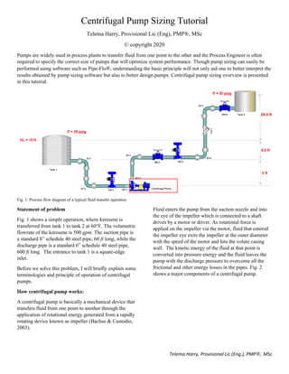
It is now time to solve the problem depicted in Fig 1.
Having discussed some basic concepts and terminology.
The data required to size a given pump is the system
flow rate and the head. The flow rate is a system
requirement and it must have been determined as part of
the overall system design. Let’s follow the steps below:
1. The Total Dynamic Head ℎA of the pump shall be
calculated using equation (1b).
Since there is no another external mechanical device
ℎ 𝑅 = 0.
Furthermore, at the surface of the fluid in the tank,
the velocity is negligible.
The Energy added by the pump to move the fluid
from tank 1 to tank 2 becomes.
ℎ 𝐴 = (
𝑝2−𝑝1
𝛾
) + (𝑧2 − 𝑧1) + ℎ 𝐿
The frictional and minor energy losses in the
systems - ℎ 𝐿 is given by
ℎ 𝐿 = ℎ 𝐿 at suction pipe + ℎ 𝐿 at discharge pipe
First we shall determine if the flow in the pipe is
laminar or turbulent by calculating the Reynold’s
number. The calculated Reynold’s number indicates
that we have turbulent flow in the system.
For turbulent flow, the energy loss due to friction is
determined by Darcy-Weisbach equation (3)
2. Determine the NPSH for the system using equation
(12) and (14)
5. Telema Harry, Provisional Lic (Eng.), PMP®, MSc
3. Determine the power requirement for the pump
using equation (10) and (11)
4. At this stage, we have determined all the design
specification of the pump. It is now time to
determine the impeller diameter, efficiency and
actual power requirement of the pump.
This last piece of the puzzle can be found on the
manufacturers pump curve. We shall use the pump
performance curve shown in Fig. 3 for this example.
How to read the pump curve is not covered in this
tutorial. The following is determined from the pump
curve:
Impeller diameter = 10.5”
Input power = 15 Hp.
NPSH required = 15 ft
The NPSHa and NPSHr are in the ratio of 11: 1, also
commonly referred to as the NPSH margin. Cavitation
can occur if the NPSH margin is very low.
Volumetric flow rate: Q 0.031545 Elevation at tank 1 3.5052 m
Pressure at Tank 1 (abs) 342.642 KPa Elevation at tank 2 12.5 m
Pressure at Tank 2 (abs) 446.063 KPa
Density 840 viscosity 0.00164 Pa.s
specific gravity - s.gr 0.8404 Vapor Pressure 700 Pa
Specific weight - γ 8240.4
18.288 m Length of pipe 182.88 m
0.2027 m Diameter: D 0.154051 m
0.000046 m wall roughness: ε 0.000046 m
0.0002269 Relative Roughness: ε/ D 0.000298602
0.0322535 Area - A 0.018629393
90.222003 L/D 1187.139324
0.9780327 m/s Velocity 1.693291902 m/s
101541.26 Renolds number: 133607.7933
0.019 Friction factor : f 0.018
0.0487537 m Velocity Head 0.146138505 m
K Energy Loses K Energy Loses
Entrance: 0.5 0.0243769 m Exit loss 1 0.146138505 m
Pipe: 1.714218 0.0835745 m Discharge pipe 21.3685 3.122761785 m
Elbow 1: 0.57 0.0277896 m Reducer RT-2: 0.22 0.032150471 m
Elbow 2: 0.57 0.0277896 m Elbow 3: 0.54 0.078914793 m
Gate valve: 0.152 0.0074106 m Elbow 4: 0.54 0.078914793 m
Reducer RT-1: 0.22 0.0107258 m Elbow 5: 0.54 0.078914793 m
Gate valve Mk-1: 0.144 0.021043945 m
Globe valve GV-2: 6.12 0.89436765 m
Gate valve Mk-2: 0.144 0.021043945 m
0.181667 m 4.474250677 m
Friction Head 4.6559177 m Pressure Head 41.58074851 m
Pressure Head 12.550483 m Static Head 8.9948 m
Static Head 8.9948 m Vapour pressure Head 0.084947333 m
Friction Head 0.181666989 m
26.201201 m 50.30893419 m
85.961947 ft 165.0555636 ft
6810.8297 W
9.1334714 Hp
9081.1062 W 45.73539471 m
12.177962 Hp 150.0505124 ft
Energy Loses in Discharge Pipe
Hydraulic Horsepower
Assuming efficiency of 75%
Power supplied to the pump
Energy Loses in Discharge
Pipe
Energy losses in suction pipe
NPSHa > 1.10 NPSHr
Applying a 10% design factor
NPSHr ˂
NPSH available DeterminationPump Head Requirement
Pump Power Requirement Pump NPSH required
NPSH availableTotal Dynamic Head
Energy Loses in Suction Pipe
System Data in SI unit
Piping Properties
Suction Pipe: 6 in schedule 40 steel pipeSuction Pipe: 8 in schedule 40 steel pipe
Fluid Properties
Relative Roughness - ε/ D
Length of pipe
Diameter: D
wall roughness: ε
Area - A
L/D
Velocity
Renolds number:
Friction factor: f
Velocity Head
𝑚3/𝑠
𝐾𝑔/𝑚3
𝑚2
𝑁 𝑅 𝑁 𝑅
𝑚2
For valves and fittings 𝐾 =
𝐿 𝑒
𝐷
𝑓
Where
𝐿 𝑒
𝐷
is the equivalent length
𝐾𝑔/𝑠2 𝑚2
6. Telema Harry, Provisional Lic (Eng.), PMP®, MSc
Fig. 3. Manufacturer’s pump curve of a pump operating at a rotational speed of 1760 rpm
In general, a centrifugal pump operating in a particular
system will deliver flow or capacity which corresponds
to the point of intersection between the Head-Capacity
curve and System curve (Bloch & Budris, 2010). This
point of intersection is called the operating point.
The system curve can be easily plotted using the general
energy equation – equation (1b). The system curve is not
shown here.
In summary, the pump selected must be able to increase
the inlet pressure to the desired outlet pressure. It must
also raise the fluid by the amount of elevation difference
between tank 1 and tank 2. It must also supply enough
energy into the system to overcome any frictional losses
in the system and it must be able to increase the velocity
in the suction pipe to the velocity in the discharge pipe.
Bibliography
American Petroleum Instite. (2010). Centrifugal Pumps
for Petroleum, Petrochemical and Natural Gas
Industries (11th ed.). Washington: API
Publishing Services.
ANSI/HI. (2017). American National Standard for
Rotodynamic Pumps — Guideline for NPSH
Margin. United States of America: Hydraulic
Institute.
Bachus, L., & Custodio, A. (2003). Know and Understand
Centrifugal Pumps. Oxford, UK: Elsevier Ltd.
Bloch, H. P., & Budris, A. R. (2010). PUMP User's
Handbook: Life Extension (3rd ed.). Lilburn, GA:
Fairmont Press, Inc.
Design point
7. Telema Harry, Provisional Lic (Eng.), PMP®, MSc
Boyce, M. P. (1999). Transport and Storage of Fluids. In
R. H. Perry, D. W. Green, & J. O. Maloney (Ed.),
Perry's Chemical Engineers' Handbook (pp. 883-
1034). New York: McGraw Hill.
Fantagu. (2008). Parts of a centrifugal pump.
Wikimedia. Retrieved 08 04, 2020, from
https://commons.wikimedia.org/w/index.php?c
urid=4332102
Head, C. C. (1996). Cameron Hydraulic Data: A Handy
Reference on the Subject of Hydraulics, and
Steam (18th ed.). U.S.A: Ingersoll-Dresser
Pumps.
Mott, R. L., & Untener, J. A. (2015). Applied Fluid
Mechanics (7th ed.). Upper Saddle River:
Prentice Hall.
Nesbitt, B. (2006). Handbook of Pumps and Pumping:
Pumping Manual International. Elsevier Science
& Technology Books.
![Telema Harry, Provisional Lic (Eng.), PMP®, MSc
Fig. 2: Components of a centrifugal pump (Fantagu, 2008)
Pump Head
Head is simply the height or elevation measured in feet
(meter) a pump can raise a fluid. The higher the head the
greater the pump power. Understanding head is very
important for the maintenance engineers or operators
working in plants. Operators in chemical plants
generally work with pressure which is a function of fluid
density (i.e. P = ρgh) and they will want to know the
system pressure at every point in time. However, pump
manufacturers use head as one of the criteria for pump
selection. Unlike pressure that changes with fluid
density, the head is constant irrespective of the fluid
density.
The pump head is the measure of the net work
performed on the fluid.
General Energy Equation
This is an adaptation of the popular Bernoulli’s equation
to account for energy losses in the system.
𝑝1
γ
+ 𝑧1 +
𝑣1
2
2𝑔
+ ℎ 𝐴 − ℎ 𝑅 − ℎ 𝐿 =
𝑝2
γ
+
𝑧2 +
𝑣2
2
2𝑔
…………………………….. (1a)
ℎ 𝐴 = (
𝑝2−𝑝1
𝛾
) + (𝑧2 − 𝑧1) + (
𝑣2
2−𝑣1
2
2𝑔
) + ℎ 𝐿 + ℎ 𝑅 .(1b)
Where:
γ = specific weight, γ = ρg
𝑝
γ
= pressure head - 𝑯 𝑷
𝑧 = elevation head or static head- 𝑯 𝑺
𝑣2
2𝑔
= velocity head - 𝑯 𝒗
ℎ 𝐴 = energy added by the motor or a prime mover. It is
also called the TOTAL DYNAMIC HEAD or TOTAL
SYSTEM HEAD by some pump manufacturers (Mott &
Untener, 2015; Head, 1996).
ℎ 𝑅 = energy removed from the fluid by a mechanical
device
ℎ 𝐿 = minor energy losses due to friction on the pipe,
valve, elbows and fittings
Friction Head 𝑯𝒍
The friction head expressed in feet (ft) or meter (m) is
the energy loss in the system due to resistance to flow
between the fluid and the internal walls of the piping
system as the fluid flows along the pipe.
Over the years, several methods have been proposed to
calculate the frictional loss in pipes. Two popular
methods are discussed below:
The Hazen - Williams formula
This formula was very popular for the calculation
frictional losses in pipes among engineers because of
ease and simplicity before the advent of computers. The
frictional loss in US customary unit ins presented below:
ℎ 𝐿 = 𝐿 [
𝑄
1.32𝐴 𝐶ℎ 𝑅0.63]
1.852
………………………… (2)
Where:
ℎ 𝐿 = Energy losses in the system due to friction in pipes
in ft
Q = is the volumetric flow rate in 𝑓𝑡/𝑠3
A = cross-sectional area of the pipe in 𝑓𝑡2
L= Length of the pipe in ft
R = Hydraulic radius of flow conduit in ft
𝐶ℎ= Hazen-Williams coefficient. A dimensionless
number.
This formula gives great result when it is water flowing
through a pipe of diameter between 2 in and 6 ft, and a
maximum velocity of 10.0 ft/s (Mott & Untener, 2015)
Darcy - Weisbach equation
Darcy - Weisbach formula is presently the most widely
used formulas for calculating frictional losses in pipes It
can be written mathematically as:](data:image/gif;base64,R0lGODlhAQABAIAAAAAAAP///yH5BAEAAAAALAAAAAABAAEAAAIBRAA7)