
Recomendados
Mais conteúdo relacionado
Mais procurados
Mais procurados (20)
Destaque
Destaque (20)
Semelhante a TSG_2016_Poster_7a
Semelhante a TSG_2016_Poster_7a (20)
TSG_2016_Poster_7a
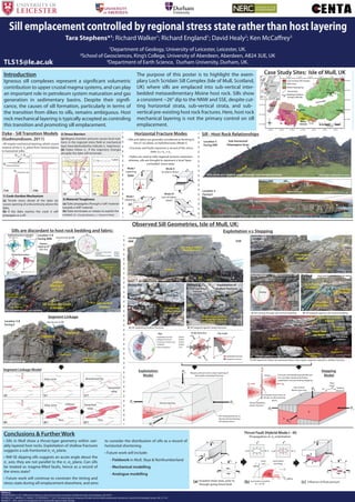
- 1. off-shoot cuts foliation Shallow dipping sill (NW Dip) Shallow dipping sill (SSE Dip) Location 3-A Facing NNE abandoned tip Melted lenses of host rock fractures cut sill and host Sub-vertical foliation (a) Sill contact discordant to foliation Bedding (12) 0 90 Dip angle 0 90 180 270 Strike direction HR-Fractures (53) 0 90 Sill-HR contact (77) 0 90 180 270 Sill-Host Rock Contacts Bedding & Fractures in Host Rock N Sill-Host Rock Contact (Poles) Key Fractures in Host rock (Poles) Bedding (Poles) Sill cuts vertical host rock bedding Magma pressure and σ1 cause opening of favourably orientated fractures fracture opening inflation progressive inflation and opening σ1 σ1 σ2 σ3 Pre-existing fracture, or fracture formed during sill emplacement Exploitation Model 0 90 Stepped Fractures 0 90 180 270 Dip angleStrike direction Exploited Fractures Exploited Fracture (Poles) Stepped Fracture (Poles) Key Fractures in Host rock (Poles) Foliation (Poles) Flow Lineations (T,P) N 20 cm no sill exploiting fractures Arrows indicate amount of rotation/ displacement due to sill inflation in fracture Sill Sill HR Exploitation of shallow fractures B) Sill stepped against steep fractures BA Sill Sub-vertical foliated Moine host rock Location 2-A NNE SSW Facing E Step F Fracture F Fracture Host Rock F 4 cm Facing ENE Sill exploiting shallow fracture F F A) Sill exploiting shallow fractures A B Fractures σ1 σ2 σ1 σ2 1 m Sill (Segment 2) Sill (Segment 1) Facing S Down-Step (to West) Exploitation of shallow fracture No intrusion in fracture Fracture roof‘uplift’ Sub-vertical foliation Segment linkage via step Sill parallels foliation Sill parallels foliation Sill Sill obliquely cuts foliation Location 2-B Facing NW Sill Facing N Down-Step (to West) Sill parallel to foliation 20 cm no instrusion in foliation A B B 232.07 bottom contact top contact Facing WNW Sill A 20 cm 1 m Sub-vertical foliation Sill C C B) Sill stepped against sub-vertical beddingA) Sill cutting through sub-vertical bedding C) Sill segments linked via westward down-step. upper segment exploits a shallow fracture. (Sill highlighted red for clarity) (Sill highlighted red for clarity) (host rock highlighted blue for clarity) Exploitation v.s Stepping Observed Sill Geometries, Isle of Mull, UK: Sill segment linkage 1.5 m abandoned tip (exploitation) Segment 1 abandoned tipLocation 3-B Facing E HR (a) Host rock Segment 2 Sills are discordant to host rock bedding and fabric: Segment Linkage σ3 σ1 σ1 Fractures and bedding perpendicular to σ1 are kept closed, preventing exploitation and promoting stepping. Vertical bedding plane/ fracture Sub-vertical Moine host rock B B A Inflation Increased shear stress at sill tips on discontinuity plane σ1σ1 σ3 σ2 Steping direction Step trend A Stepping Model Segment Linkage Model (a’’) breached relay abandoned tip (b) (b’’) flow breached relay inflation flow (b’) relay zone (a) (a’) relay zone σ1 σ1 σ3 σ1 σ1 σ3 1 Department of Geology, University of Leicester, Leicester, UK. 2 School of Geosciences, King’s College, University of Aberdeen, Aberdeen, AB24 3UE, UK 3 Department of Earth Science, Durham University, Durham, UK.TLS15@le.ac.uk Sill emplacement controlled by regional stress state rather than host layering Tara Stephens*1 ; Richard Walker1 ; Richard England1 ; David Healy2 ; Ken McCaffrey3 N Bedding Sill - Host rock contact References GUDMUNDSSON, A. 2011. Deflection of dykes into sills at discontinuities and magma-chamber formation. Tectonophysics, 500, 50-64. SCHOFIELD, N. J., BROWN, D. J., MAGEE, C. & STEVENSON, C. T. 2012. Sill morphology and comparison of brittle and non-brittle emplacement mechanisms. Journal of the Geological Society, 169, 127-141. WALKER, R. J. 2016. Growth of a transgressive sill in mechanically layered media. Geology. (a) (c) Thrust Fault (Hybrid Mode I - III) Propagation in σ2 orientation B B’ σ1 σ1 σ3 σ2 σ3 σ1 B B’ Influence of fluid pressureIncipient shear zone, prior to through-going thrust fault σ2 σ3 σ1 A A’ A A’ σ1 σ1 σ3 τ (MPa) σn (MPa) reactivation possible θ ≈ 10-50° 2θ Pf reactivation envelope intact rock σ3 σ1 σ1 σ3 σ1 σ1 Pf (b) σ1 σ2 σ3 σ1σ2σ3 σT (Intrusion tip) σT (Discontinuity) σT (I) > σT (D) (1a) (1b) 1) Cook-Gordon Mechanism (a) Tensile stress ahead of the dyke tip causes opening of a discontinuity above the dyke. (b) If the dyke reaches the crack it will propagate as a sill. Dyke - Sill Transition Models (Gudmundsson, 2011) 2) Stress Barriers (a) Magma chamber pressure causes local rota- tions in the regional stress field at mechanical layer boundaries(dashes indicate σ1 trajectory). (b) Dykes follow σ1 . If the trajectory changes abruptly the dyke will terminate. ~10 m 3) Material Toughness (a) Dyke propagates through a‘soft’material towards a‘stiff’material. (b) Dyke terminates or rotates to exploit the contact. (E = Young’s Modulus, v = Poisson’s Ratio) • All require mechanical layering, which causes rotation of the σ1 -σ2 plane from vertical (dykes) to horizontal (sills). σ1 Pf (b) (a) σ1 σ1 (2) E & v E & v Tuff Lava (a) (b) (3) Introduction Igneous sill complexes represent a significant volumetric contribution to upper crustal magma systems, and can play an important role in petroleum system maturation and gas generation in sedimentary basins. Despite their signifi- cance, the causes of sill formation, particularly in terms of the transition from dikes to sills, remains ambiguous. Host rock mechanical layering is typically accepted as controling this transition and promoting sill emplacement. The purpose of this poster is to highlight the exem- plary Loch Scridain Sill Complex (Isle of Mull, Scotland, UK) where sills are emplaced into sub-vertical inter- bedded metasedimentary Moine host rock. Sills show a consistent ~26° dip to the NNW and SSE, despite cut- ting horizontal strata, sub-vertical strata, and sub- vertical pre-existing host rock fractures. Here, host rock mechanical layering is not the primary control on sill emplacement. Conclusions & Further Work • Sills in Mull show a thrust-type geometry within vari- ably layered host rocks. Exploitation of shallow fractures suggests a sub-horizontal σ1 -σ2 plane. • NW-SE dipping sills suggests an acute angle about the σ1 axis; they are not parallel to the σ1 -σ2 plane. Can sills be treated as magma-filled faults, hence as a record of the stress state? • Future work will continue to constrain the timing and stress state during sill emplacement elsewhere, and aims to consider the distribution of sills as a record of horizontal shortening. • Future work will include: - Fieldwork in Mull, Skye & Northumberland - Mechanical modelling - Analogue modelling Case Study Sites: Isle of Mull, UK 6°0'0"W 6°0'0"W 6°4'0"W 6°4'0"W 6°8'0"W 6°8'0"W 6°12'0"W 6°12'0"W 6°16'0"W 6°16'0"W 6°20'0"W 6°20'0"W 6°24'0"W 6°24'0"W6°26'0"W6°28'0"W 56°26'0"N 56°24'0"N 56°24'0"N 56°22'0"N 56°22'0"N 56°20'0"N 56°20'0"N 56°18'0"N 56°18'0"N 56°16'0"N Ross of Mull Pluton L4 L1-3 L5 Iona Bunessan Loch Scridain Carsaig Mull Lavas Loch Scridain Sill Complex Moine Supergroup Assapol Fault Thrust Fault 50 km N Scotland Isle of Mull 76 Moine foliation 21 Lava units Bedding/ Foliation average strike.dip 76 Horizontal Fracture Modes • Sills and dykes are generally considered as forming in the σ1-σ2 plane, as hydrofractures (Mode I). • Fractures and faults represent a record of the stress state: σ1 ≥ σ2 ≥ σ3 . • Dykes are used to infer regional tectonic extension, whereas, sills are thought to represent a local 'layer- controlled' stress state. Mode I (opening) σ3 σ3 σ1 σ2 Mode II (in-plane shear) Mode III (out-of-plane shear) σ1 σ3 σ1 σ2 σ2 σ3 σ1 σ3 σ1 σ3 σ2 Dyke Sill Mode I (opening) Sill DykeSub-horizontal Palaeogene lavas Sill Location 5 Facing ENE Sills climb at a shallow angle through sub-horizontal lavas Sill (Sills & dyke highlighted for clarity) Sills climb at a shallow angle through sub-vertical Moine host rock - arrows indicate sill top & base Location 3 Facing E 3 m Facing ENE Sill (highlighted red for clarity) SSE dip NW dip Sill Moine host rock 3B 3A (Sill highlighted red for clarity) Sill - Host Rock Relationships