Hydel Generation and Types Of Turbines
•Transferir como PPTX, PDF•
1 gostou•618 visualizações

* Catchment area = 200 sq.km = 200,000,000 sq.m * Average rainfall = 130 cm = 1.3 m * Runoff = 70% of rainfall = 0.7 * 1.3 = 0.91 m * Water available per year = Rainfall * Runoff * Catchment area = 1.3 * 0.91 * 200,000,000 = 234,000,000 cubic meters * Head available = 380 m * Density of water = 1000 kg/cubic meter * Gravity acceleration = 10 m/sec^2 * Power = Mass of water * Gravity height * Head / Time = 234,000,000 * 1000 * 10 *

Recomendados
Mais conteúdo relacionado
Mais procurados
Mais procurados (20)
Destaque
Destaque (20)
Semelhante a Hydel Generation and Types Of Turbines
Semelhante a Hydel Generation and Types Of Turbines (20)
Mais de Taimoor Muzaffar Gondal
Mais de Taimoor Muzaffar Gondal (20)
Último
Último (20)
Hydel Generation and Types Of Turbines
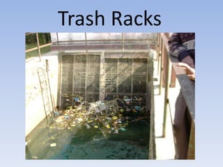
- 1. Trash Racks
- 3. Gravfoss Power Plant Norway Trash Rack size: Width: 12 meter Height: 13 meter Stainless Steel
- 4. Principle Components of a Hydro- Electric Scheme • The penstock should be located at such a level that sufficient water depth is provided above the penstock entrance in the foreway. If this is not so, and too little water depth is available, vortices and whirlpools will tend to form, which may carry air in the penstock and turbine wheels, and thus lowering efficiency of the turbine. • Sharp bends must be avoided in the penstocks, because they cause loss of head and require special anchorages.
- 5. The penstock is made of steel. As regards the location of the penstock, two different solutions may be discerned which are characteristics of the method of support as well. 1. Buried penstocks are supported continuously on the soil at the bottom of a trench backfilled after placing the pipe. The thickness of the cover over the pipe should be about 1.0 to 1.2 m. The advantages of buried pipes are the following: a) The soil cover protects the penstock against effect of temperature variations, b) It protects the conveyed water against freezing, c) Buried pipes do not spoil the landscape, d) They are safer against rock slides, avalanches and falling trees.
- 6. Disadvantages are: a) Such pipes are less accessible for inspection, faults cannot be determined easily, b) For large diameters and rocky soils their installation is expensive, c) On steep hillsides, especially if the friction coefficient of the soil is low, such pipes may slide, d) Maintenance and repair of the pipe is difficult.
- 7. 2. Exposed penstocks are installed above the terrain surface and supported on piers (briefly called supports or saddles). Consequently, there is no contact between the terrain and the pipe itself, and the support is not continuous but confined piers. The advantages of exposed pipes are the following; a) The possibility of continuous and adequate inspection during operation, b) Its installation is less expensive in case of large diameters of rocky terrain, c) Safety against sliding may be ensured by properly designed anchorages, d) Such pipes are readily accessible and maintenance and repair operations can be carried out easily.
- 8. The disadvantages are; a) Full exposure to external variations in temperature, b) The water conveyed may freeze, c) Owing to the spacing of supports and anchorages significant longitudinal stresses may develop especially in pipes of large diameters designed for low internal pressures. As a general rule, buried pipes are applied only on mildly sloping terrain where the top layers do not consist of rock. The exposed arrangement is more frequently applied. The main advantage of exposed penstocks is the possibility of continuous inspection during operation. Concrete blocks holding the pipeline may be simple supporting piers permitting slight longitudinal movement of the pipe, or anchor blocks which do not permit movement of the pipe. Anchorages are usually installed at angle joints, while supporting piers are spaced rather closely (6 to 12 m) depending on the beam action of the pipe and the supporting capacity of the soil.
- 9. In order to reduce the longitudinal stresses due to the temperature variations and other causes, rigid joints between pipe sections should in some places be substituted by elastic ones. Large power penstocks subject to heads of several hundred meters may be constructed of banded steel pipes. Simple steel pipes are used for, pD <10000(kg cm) Banded steel pipes for, pD >10000(kg cm) Where p (kg/cm2) internal pressure, and D (cm) pipe diameter.
- 10. Principle Components of a Hydro- Electric Scheme • Surge Tank or Surge Chamber • The simplest type of a surge chamber consists of a cylindrical chamber open to atmosphere and connected to the penstock as close to the power house as possible. • When the load is rejected by the power house turbine, the water level in the surge chamber rises, and decelerates the flow upstream of it. But when additional load comes, the immediate demand is met by drawing water from the surge chamber, which accelerates the flow gradient and thus accelerates the flow in the reservoir. A surge tank therefore reduce the pressure fluctuations in the conduit pipe considerably, and thus prevents additional water hammer pressure from being exerted upon the wall of the conduit.
- 11. Principle Components of a Hydro- Electric Scheme • Various types of surge tanks such as (i) simple surge tank (ii) Throttled surge chamber (iii) Differential surge chamber (iv) Multiple surge chamber. • The main advantage of differential type of surge tank over simple tank lies in the fact that the retarding & accelerating heads are developed more quickly in differential types
- 12. Surge Tank or Surge Chamber
- 13. Surge Tank or Surge Chamber
- 14. Surge Tank or Surge Chamber
- 15. Principle Components of a Hydro- Electric Scheme • Hydraulic Turbines • Turbines are machines which convert hydraulic energy into mechanical energy. The mechanical energy so developed by the turbine is then used to generate electric energy by direct coupling of the shaft of the turbine with generator. • In general, a turbine consists of wheel which is provided with special designed blades or buckets. The water having large hydraulic energy is made to strike the runner, and thus cause it to rotate. This rotation of the turbine runner is passed on to the generator by coupling the generator and turbine together through the turbine shaft. This results in rotating the generator armature, and thus producing electrical power, called hydroelectric power.
- 17. Principle Components of a Hydro- Electric Scheme • Hydraulic Turbines may be of two classes: • (i) Impulse Turbines or Velocity Turbines and • (ii) Reaction turbines or Pressure turbines • These are discussed below: (i) Impulse Turbine. • The important example of an impulse type of turbine is Pelton’s wheel In such a turbine, all the available potential energy of water is converted into kinetic energy by passing the penstock water through a single nozzle. The water coming out of the nozzle in the form of free jet is made to strike a series of buckets mounted on the periphery of a wheel. This causes the wheel to revolve in open air, and water is in contact with only a part of the wheel at a time. • An impulse turbine is essentially a low speed turbine and is used for high heads of the order of 150 to 1000m. Since it works under high heads. Comparatively less quality of water. Since it works under high heads, comparatively less quantity of water is required. It is therefore used for high heads and low discharges.
- 18. Impulse Turbine.
- 20. Principle Components of a Hydro- Electric Scheme (ii) Reaction Turbine • The important example of reaction turbine are (i) Fancis turbine; and Kaplan turbine. A reaction turbine is one in which only a part of potential energy of water is converted into velocity head and the balance remains as pressure head. Thus the water entering the turbine possesses pressure as well as kinetic energy. The wheel is rotated under the action of both these forces. The water leaving the turbine also contains some pressure as well as velocity head. The pressure at the inlet is much higher than the pressure at the outlet. Since the entire flow takes place under pressure, a closing case is absolutely necessary, so as to prevent access of atmosphere air into the turbine. Since the water flows under pressure through such a turbine, the wheel of this turbine are submerged, and water enters all around the periphery of the wheel.
- 21. Kaplan Turbine
- 22. Kaplan Turbine
- 23. Francis Turbine
- 24. Francis Turbine
- 25. Difference Between Pelton’s and Francis Turbine • In a Pelton’s wheel, the total potential head is changed into kinetic head for affecting the motion of the runner; while in a francis wheel, only a part of it is converted. • Water strikes only a few buckets at a time in Pelton’s wheel while in francis turbine wheel the water flows like that in a closed conduit. The runner is always full of water, and thus all the blades are simultaneously stricken by water. • In Pelton’s wheel, the water falls freely to the atmosphere; while in Francis wheel, the water is taken upto the tailrace by means of a closed draft tube, and thus, the whole passage of water is totally enclosed.
- 26. Principle Components of a Hydro- Electric Scheme • Power House • A power house is a building consisting of a substructure to support the hydraulic and electric equipment and a super structure to house and protect this equipment. For most of the plants which are equipped with reaction turbines, the substructure usually consists of a concrete block extending from the foundation to the generator floor with waterways formed within it. They are cast integrally while pouring concrete. • The super structure is a building which generally accommodates the generator and excitors on the ground floor, and the switch board and control room on the mezzanine floor. Vertical turbines are placed on the ground floor along side the generators. A travelling crane spanning the width of the power house, is generally provided in every power hose, so as to facilitate the lifting of heavy machines.
- 27. Power House
- 28. Power House
- 29. Merits & Demerits of Hydro Electric Power • Merits • Once a dam is constructed, electricity can be produced at a constant rate. • If electricity is not needed, the sluice gates can be shut, stopping electricity generation. The water can be saved for use another time when electricity demand is high. • Dams are designed to last many decades and so can contribute to the generation of electricity for many years / decades. • The Reservoir that forms behind the dam can be used for water sports and leisure / pleasure activities. Often large dams become tourist attractions in their own right. • The Reservoir water can be used for other purposes such as irrigation. • Minimum operating staff is required for the operation of hydro power plant. • Non Polluting and hence environmental friendly energy is produced. • Low cost of energy generation & maintenance.
- 30. Merits & Demerits of Hydro Electric Power • Demerits • Land acquisition is the major problem as construction of dam causes large submergence of land. Many political, regional, and social hurdles comes in the process of land acquisition • Hydro- Power project takes long time for clearance. • Rehabilitation and resettlement of displaced people is a major problem associated to any hydropower project. • Large scale initial investment is required.
- 31. Merits & Demerits of Hydro Electric Power • The high cost of dam construction means that they must operate for many decades to become profitable. • The Submergence of large areas of land means that the natural environment is destroyed. • The building of large dams can cause serious geological damage. • Although modern planning and design of dams is good, in the past old dams have been known to be breached this has led to deaths and flooding. • Dams built blocking the progress of a river in one country usually means that the water supply from the same river in the following country is out of their control. This can lead to serious problems between neighboring countries. • Building a large dam alters the natural water table level.
- 32. Capital cost of hydro power plants • Small hydro, $1000-3000/kW, developing countries • Small hydro, $2000-9000/kW, developed countries • Large hydro (involving dams and reservoirs), $2000-8000/kW (including access roads for high estimates)
- 33. Small-hydro capital cost 0 1000 2000 3000 4000 5000 6000 7000 8000 9000 10000 0 500 1000 1500 2000 kW Installed US$/kW Developing country International data Source: Paish (2002, Renewable and Sustainable Energy Reviews 6, 537–556, http://www.sciencedirect.com/science/journal/13640321)
- 34. Cost of hydro-electricity (cents/kWh) Table Cost of hydro-electric energy (cents/kWh) for various capital costs, interest rates, and capacity factors, assuming amortization of the initial investment over a 50-year period. Operation and maintenance, insurance, water rent, transmission, and administrative costs are not included.
- 35. A hydro electric station is to be designed for a catchment area of 200 sq. km. run off of 70% and the average rainfall of 130 cm. per annum. The head available is 380 m. What power can be developed if the overall efficiency of the plant is 80%?