SlideShare uma empresa Scribd logo
1 de 36
Baixar para ler offline
Rupture Disks for Process Engineers - Part 1
This is a real story. A rupture disk manufacturer presented a seminar to a group consisting of junior and more senior
level process design engineers (yours truly included) with a few instrument engineers thrown in. After about an hour
of hearing terms such as bursting pressure, tolerance, manufacturing range, etc., and discussions on the mechanical
aspects that differentiate the various types of rupture disks, the seminar ended with many of those attending just
shaking their heads. Most of the attendees just wanted to learn how to specify this item so the instrument engineer
can buy one or the manufacturer can tell you what is needed.
I eventually put together a seminar on rupture disks for process design engineers that went over very well. This series
of articles is taken from that seminar. Part 1 covers the whys and when to use a rupture disk. Part 2 covers how to
size the rupture disk. Subsequent parts will include how to set the burst pressure, the Relief Valve/Rupture Disk
combination, how to specify the device and some discussion on the type of rupture disks you can purchase.
Before I begin, let me point out that most of what is included in this series of articles can be found in API RP5201
and
API RP5212
, and ASME Section VIII, Division 13
. Much of what is found in these documents can also be found in
vendor literature.
Why and When to Use Rupture Disks
Why Do We Use a Stand-Alone Rupture Disk?
A rupture disk is just another pressure relieving device. It is used for the same purpose as a relief valve, to protect a
vessel or system from overpressure that can cause catastrophic failure and even a death.
When Do We Use a Stand-Alone Rupture Disk?
Some of the more common reasons are listed below. You may think of others.
Figure 1: Basic Components of a Rupture Disk
1. Capital and Maintenance Savings: Rupture disks cost less than relief valves. They generally require little to no
maintenance.
2. Contents will be lost, but who cares? A rupture disk is a nonreclosing device, which means once it opens, it
doesn't close. Whatever is in the system will get out and continue to do so until stopped by some form of intervention.
If loss of contents is not an issue, then a rupture disk may be the relief device of choice.Â
3. Benign service: It is preferable that the relieving contents be non-toxic, non-hazardous, etc. However, this is not
a requirement when deciding to use, or not use, a stand-alone rupture disk.
4. Rupture disks are extremely fast acting: Rupture disks should be considered first when there is a potential for
runaway reactions. In this application, relief valves will not react fast enough to prevent a catastrophic failure. A relief
valve may still be installed on the vessel to protect against other relieving scenarios. Some engineers prefer to use
rupture disks for heat exchanger tube rupture scenarios rather than relief valves. They are concerned that relief
valves won't respond fast enough to pressure spikes that may be experienced if gas/vapor is the driving force or
liquid flashing occurs.
5. The system contents can plug the relief valve during relief: There are some liquids that may actually freeze when
undergoing rapid depressurization. This may cause blockage within a relief valve that would render it useless. Also, if
the vessel contains solids, there is a danger of the relief valve plugging during relief.
6. High viscosity liquids. If the system is filled with highly viscous liquids such as polymers, the rupture disk should
seriously be considered as the preferable relieving device. Flow through a relief valve will be very difficult to calculate
accurately. Also, very viscous fluid may not relieve fast enough through a relief valve.
Cost Comparison Between Comparable Stand-Alone Rupture Disk and Relief Valve
Rupture disk manufacturers burst at least two disks per lot before shipping them to a customer.
As a consequence even if you want just one rupture disk you will be buying three. Therefore, the first usable rupture
disk is comparatively expensive. Also for new installations, each installed rupture disk must be purchased along with
a holder. However, the same holder may be used for replacement purchases as long as you buy the exact same
rupture disk from the same manufacturer.
Below is a capital cost comparison between Continental Disc Corp. (www.contdisc.com) 3" Ultrx Hastelloy C rupture
disks with holders and Farris Engineering (www.cwfc.com) 2600 series relief valves, based on a budget estimate in
year 2001 dollars.
Â
Table 1: Cost Comparison - Rupture Disk vs. Relief Valve
Figure 2: Rupture Disk Mounted on a Vessel
Basis: Continental Disc Basis: Farris Engineering
3" Ultrx Hast C Disc = $2,600 for 1st
usable
disk, then $870 each
3" x 4" Hast C 26KA10-120 = $13,400
3" Ultrx Hast C Holder = $3,300 ea. Â
TOTAL for one pair = $5,900 Â
TOTAL for three pair = $14,240 TOTAL for three = $40,200
This capital cost comparison will vary considerably with size and material of construction but you get the point.
However please note that everything has a value and the loss of contents should be considered in the overall cost
difference between a rupture disk and a relief valve.
When Do We Use a Rupture Disk-Relief Valve Combination?
Rupture disks are often used in combination with and installed just upstream and/or just downstream of a relief
valve. You may want to choose the combination option if:
Â
1. You need to ensure a positive seal of the system (the system contains a toxic substance and you are concerned
that the relief valve may leak). Application: rupture disk installed upstream of the relief valve.
2. The system contains solids that may plug the relief valve over time. Remember, the relief valve is continuously
exposed to the system. Application: rupture disk installed upstream of the relief valve.
3. TO SAVE MONEY! If the system is a corrosive environment, the rupture disk is specified with the more exotic
and corrosion resistant material. It acts as the barrier between the corrosive system and the relief valve. Application:
rupture disk installed either upstream and/or downstream of the relief valve.
Figure 3: Rupture Disk-
Relief Valve Combination
Below is a capital cost comparison between combination Hastelloy C rupture disks with stainless steel relief valves
and three stand-alone Hastelloy C relief valves. Again, this is based on a budget estimate in year 2001 dollars using
Continental Disc Corp. rupture disks and holders and Farris Engineering relief valves.
Table 2: Cost Comparison for Rupture Disk-Relief Valve Combinations
Basis: Continental Disc Basis: Farris Engineering
3" Ultrx Hast C Holder = $3,300 3" x 4" Hast C 26KA10-120 = $13,400
3" Ultrx Hast C Disc = $2,600 for 1st
usable
disk, then $870 each
3" x 4" SS 26KA10-120 = $4,300
Combination of Hastelloy C Disk and SS Relief Valve
Single Installation Total = $10,200
Total for three installations = $27,140
Three stand-alone Hastelloy C relief valves = $40,200
Summary
A stand-alone rupture disk is used when:
1. You are looking for capital and maintenance savings
2. You can afford to loose the system contents
3. The system contents are relatively benign
4. You need a pressure relief device that is fast acting
5. A relief valve is not suitable due to the nature of the system contents
A rupture disk / relief valve combination is used when:
1. You need to ensure a positive seal of the system
2. The system contains solids that may plug the relief valve over time
3. TO SAVE MONEY! If the system is a corrosive environment, the rupture disk is specified with the more exotic and
corrosion resistant material
References
1. API (www.api.org) Recommended Practice 520, "Sizing, Selection, and Installation of Pressure-Relieving Device in
Refineries, Part 1-Sizing and Selection", 7th
Edition (January 2000)
2. API (www.api.org) Recommended Practice 521, "Guide for Pressure-Relieving and Depressuring Systems",
4th
Edition (March 1997)
3. ASME (www.asme.org) "Boiler and Pressure Vessel Code, Section VIII, Division 1" (1998)
Rupture Disks for Process Engineers - Part 2
Part 1 of this series on rupture disks for Process Engineers covered why you use a rupture disk and when you might
want to use this device. This part will discuss how to size the rupture disk. Subsequent parts will include how to set
the burst pressure, the Relief Valve/Rupture Disk combination, how to specify the device and some discussion on the
type of rupture disks you can purchase.
Before I begin, let me point out that most of what is included in this series of articles can be found in API RP5201
and
API RP5212
, and ASME Section VIII, Division 13
. Much of what is found in these documents can also be found in
vendor literature
Sizing
Sizing the rupture disk is a two-part procedure. First, determine how much flow the rupture disk needs to pass. Then
determine how big it needs to be.
How much flow does it need to pass?
Answering this question is the same as determining the required relieving rate for the system. There is no difference
between determining the relieving rate for a rupture disk and a relief valve. They both require a set pressure (burst
pressure for rupture disk), an allowable overpressure, an evaluation and calculation of the required relieving rate for
each credible scenario and then choosing the flow rate associated with the worst-case scenario. Determining the
controlling relieving rate is a paper in of itself and I will not attempt to get into details here.
How Big?
There are two recognized methods that can be used to answer this question, the Resistance to Flow Method or the
Coefficient of Discharge Method.
Resistance to Flow Method
The Resistance to Flow Method analyzes the flow capacity of the relief piping. The analysis takes into account
frictional losses of the relief piping and all piping components. Calculations are performed using accepted engineering
practices for determining fluid flow through piping systems such as the Bernoulli equation for liquids, the Isothermal or
adiabatic flow equations for vapor/gas and DIERS methodology for two-phase flow.
Piping component losses may include nozzle entrances and exits, elbows, tees, reducers, valves and the rupture
disk(note that the rupture disk and its holder are considered a unit). Let me emphasize that in this method, the rupture
disk is considered to be just another piping component, nothing more, and nothing less. Therefore the rupture disk's
contribution to the over all frictional loss in the piping system needs to be determined. This is accomplished by using
"Kr", which is analogous to the K value of other piping components. Kr is determined experimentally in flow
laboratories by the manufacturer for their line of products and is certified per ASME Section VIII, Division 13
. It is a
measure of the flow resistance through the rupture disk and accounts for the holder and the bursting characteristics
of the disk.
Below is a list of some models of Continental Disc Corporation rupture disks with their certified Kr values4
.
Table 1: Rupture Disks from Continental Disc Corp.
Rupture Disk (and holder) Type Media Size Range Kr
ULTRX Gas, Liquid 1" - 12" 0.62
ULTRX Gas only 1" - 12" 0.36
MINTRX Gas, Liquid 1"- 8" 0.75
STARX Gas, Liquid 1" - 6" 0.38
SANITRX Gas, Liquid 11/2" - 4" 3.18
Â
For comparison, the following is a list of some models of Fike rupture disks with their certified Kr values5
.
Table 2: Rupture Disks from Fike
Rupture Disk (and holder) Type Media Size Range Kr
SRX - 1" - 24" 0.99
SRL - 1" - 8" 0.38
SRH - 1 1/2" - 4" 1.88
HO / HOV - 1" - 24" 2.02
PV, CPV, CP-C, CPV-C - 1/2" - 24" 3.50
If at the time of sizing the manufacturer and model of the rupture disk are unknown, there are guidelines to help you
choose Kr. API RP5212
recommends using a K of 1.5. However, ASME Section VIII, Division 13
states that a Kr of
2.4shall be used. Which one? Remember that ASME is Code (meaning LAW for the most part) and API is a
recommended practice. In addition, as can be seen in the tables above, even ASME may not be as conservative as
you may think. Therefore, it is in the engineer's best interest to determine ahead of time the manufacturer and model
of the rupture disk that eventually will be purchased. This can be done without knowing the exact size, as Kr is more
manufacturer and model specific than size specific (see above tables). If a number of manufacturers are on the
allowable purchase list, then at the very least choose the most likely models you would buy from each manufacturer
and use the largest Kr from that list. This will be a significantly better guess than just using guidelines.
Once the piping system is laid out and all the fitting types are known, including the rupture disk, the engineer can
proceed with the calculations in the following manner (presented here as a suggestion, there are many ways to do it).
1. Known are the two terminal pressures, these being the relieving pressure (upstream) and the downstream pressure
(a knock-out pot, atmosphere, etc.).
2. Also known are the fluid properties and required relieving rate (the flow the rupture disk needs to pass).
3. Choose a pipe size. This will be the size to use for all components, including the rupture disk.
4. For vapor/gas or two-phase flow, use one of the accepted calculation methods to determine
the maximum flow through the system. The maximum flow through the system is commonly
known as critical flow or choked flow. For liquids, use the Bernoulli equation to calculate the
flow that will balance the system pressure losses.
5. Per ASME Section VIII, Division 1, multiply this flow by 0.9 to take into account inaccuracies in the system
parameters. Compare the adjusted calculated flow to the required relieving rate. If it is greater, then the calculation is
basically done. However, the next smaller line size should also be checked to make sure the system is optimized; you
want the smallest sized system possible. If the adjusted calculated flow is less than the required relieving rate, the
pipe is too small, choose a larger size and repeat the calculations.
Why not just choose a large Kr? Isn't that more conservative?
Many times, relief is not to atmosphere but to some downstream collection and treatment system, e.g. knockout
drums and flares or thermal oxidizers. These are more often than not specified at a time period in the design that
predates the actual purchase of the rupture disk. The flow used to size this equipment will be based on the capacity
of your relief system as determined above.
If the rupture disk contributes a significant portion of the frictional losses to the system, a fictitiously large Kr might
result in an oversized piping system. Sounds all right on the surface but once the actual rupture disk is chosen, the
calculation must be repeated with the "real" Kr and this may be a much lower value than originally used. More fluid
will flow through the system than previously determined because there will actually be less resistance to flow. The
result is that the downstream processing equipment may have been undersized.
The opposite is also true. An initial guess of a fictitiously small Kr might ultimately result in oversized downstream
equipment and the excessive expenditure of a significant amount of money.
Atmospheric discharge must also be similarly analyzed because the flow capacity determined after rupture disk
selection may have a major impact on the emissions reported for permitting if they were based on the initial value of
Kr.
Coefficient of Discharge Model
The second calculational method is the Coefficient of Discharge Method. The rupture disk is treated as a relief valve
with the flow area calculated utilizing relief valve formulas and a fixed coefficient of discharge, ‘Kd', of 0.62. This
method does NOT directly take into account piping so there are restrictions in its use. These restrictions are known
as the "8 & 5 Rule" which states that in order to use this method to
size the rupture disk ALL of the following four conditions MUST be met3:
The rupture disk must be installed within 8 pipe diameters of the vessel or other overpressure source.
1. The rupture disk discharge pipe must not exceed 5 pipe diameters.
2. The rupture disk must discharge directly to atmosphere.
3. The inlet and outlet piping is at least the same nominal pipe size as the rupture disk.
A sketch of the "8 & 5" rule starting with a 2" nominal sized pipe is shown at the below.
The flow area calculated with this method is called the Minimum Net Flow Area or MNFA. The MNFA is the rupture
disk's minimum cross
sectional area required to meet the needed flow.
This is not the area (and thus the size) you specify. Just like a pipe with a nominal size and an actual inside diameter,
the rupture disk has a nominal size and an actual Net Flow Area or NFA. The rupture disk purchased must have a
NFA equal to or greater than the MNFA. The manufacturer publishes the NFA for every rupture disk model and size
they sell. The NFA also accounts for bursting characteristics of the disk and the holder.
Below is a list of some Continental Disc Corporation rupture disks with their NFA4
.
Â
Table 3: Continental Disc Corp Disks with NFA
Rupture Disk (and holder) Type Nominal Size, inches NFA,
in2
ULTRX 1-1/2" 2.04
ULTRX 3" 7.39
SANITRX 1-1/2" 1.18
SANITRX 3" 5.49
Once the actual NFA of the rupture disk is determined, the calculations must be repeated, basically for the same
reasons discussed above for the Resistance to Flow Method.
Why I Don't Like the Coefficient of Discharge Model
Figure 1: Diagram Showing the "8 & 5" Rule
 It's too restrictive! During the basic design phase of a project, actual piping configuration is unknown. You may think
you are within the "8 & 5" rule at first but may not be when the final details are worked out. Remember, the "5" means
5 pipe diameters. For a 3" line, that is only a nominal 15". For a 6' vertical vessel with a rupture disk discharge being
piped to a drain hub on the floor, the 15" maximum length is exceeded without even thinking.
 Using the Resistance to Flow Method is valid for all cases. All sizing calculations can be
standardized.
 The Kr used in the Resistance to Flow Method is obtained by actual flow data for a given model of rupture disk and
holder. Its use will provide a much more accurate calculation. The 0.62 coefficient of discharge used in the Coefficient
of Discharge Method is very general and independent of rupture disk manufacturer model and type, holder, disk
bursting characteristics and flow restrictions of the total relief system.
 Two-phase flow can be a major concern when using this method. The coefficient of discharge was established mainly
for true vapors. Its application to liquids is questionable and its application to two-phase flow is totally fictitious.
Granted, for the Resistance to Flow Method the Kr is not particularly applicable to two-phase systems either but one
can easily compensate for this in the system calculations. Also, the rupture disk is only a part of an entire piping
system and its overall contribution to the system frictional losses may not be greatly significant. Therefore, errors in
Kr may not be very significant. In the Coefficient of Discharge Method, it is the only device considered. If the
coefficient of discharge is grossly in error, the MNFA calculated will also be grossly in error.
 The same argument can be made for highly viscous liquid systems such as polymers.
In Summary
 Obtain the required relieving rate using good sound "what can go wrong" scenario analysis.
 Use the Resistance to Flow Method to calculate the size of the rupture disk (use the Coefficient of Discharge Method
if you really must and you fall within the "8 & 5" rule).
 For the Resistance to Flow Method, try to choose the manufacturer and model of rupture disk you intend to purchase
ahead of time or at least have a list of acceptable manufacturers and a good idea of the model you intend to use from
each.
 For the Resistance to Flow Method use the ASME Kr value of 2.4 if you have no idea who the manufacturer(s) will be
at the time of sizing.
References
1. API (www.api.org) Recommended Practice 520, "Sizing, Selection, and Installation of Pressure-Relieving Device in
Refineries, Part 1-Sizing and Selection", 7th
Edition (January 2000)
2. API (www.api.org) Recommended Practice 521, "Guide for Pressure-Relieving and Depressuring Systems",
4th
Edition (March 1997)
3. ASME (www.asme.org) "Boiler and Pressure Vessel Code, Section VIII, Division 1" (1998)
4. Continental Disc Corporation (www.contdisc.com), CertiflowTM
Catalogue 1-1112
5. Fike (www.fike.com), Technical Bulletin TB8104, December 1999
6. Another good rupture disk manufacturer to investigate would be Oseco (www.oseco.com).
7. A good reference source for calculating flow through the system for liquids and gas/vapors is CRANE Technical
Paper 410, "Flow of Fluids Through Valves, Fittings, and Pipe"
8. A great source and one that I feel should be the bible on two-phase flow is: Leung, J.C. "Easily Size Relief Device
and Piping for Two-Phase Flow", Chemical Engineering Progress, December, 1996
Rupture Disks for Process Engineers - Part 3
Part 1 of this series on rupture disks for Process Engineers covered why you use a rupture disk and when you might
want to use this device. Part 2 discussed how to size the rupture disk. In this part, I will cover how to set the burst
pressure. Subsequent parts will include temperature and backpressure affects, the Relief Valve/Rupture Disk
combination, how to specify the rupture disk and some discussion on the type of rupture disks you can purchase.
Before I begin, let me point out that most of what is included in this series of articles can be found in API RP5201
and
API RP5212
, and ASME Section VIII, Division 13
. Much of what is found in these documents can also be found in
vendor literature.
Problem
1. What is the maximum allowable specified burst pressure?
2. What should the expected stamped (rated) burst pressure of the rupture disk be?
3. At what pressure(s) can we expect the delivered rupture disk to actually burst at?
4. What is the maximum allowable operating pressure in the vessel?
All these questions must be considered in order to properly set the burst pressure of a rupture disk.
What is the Maximum Allowable Specified Burst Pressure?
Burst Pressure
What do we mean by burst pressure? This is the pressure at which the rupture disk will open or burst. It is analogous
to the set pressure of a relief valve and is specified by the process engineer.
Design Pressure
To find the maximum allowable specified burst pressure, the process engineer first needs to define a vessel design
pressure. The design pressure is an arbitrary value above the vessel maximum operating pressure. One guideline
used by many process design engineers is to increase the maximum operating pressure by 25 psig or 10%
whichever is greater. For example, if the maximum operating pressure is 70 psig, then 25 psig should be added to
arrive at the design pressure since 10% is only 7 psig. The design pressure would then be set at a nice round 100
psig. Other criteria to determine design pressure may be used but I recommend that the margins never be less than
what I described above (the reason will become apparent later).
Maximum Allowable Working Pressure (MAWP)
The next step is to determine the Maximum Allowable Working Pressure (MAWP) of the vessel. A vessel
specification stating design pressure, the coincident design temperature and other parameters is sent to the
manufacturer. The manufacturer performs a series of calculations utilizing these parameters, amongst others, to
determine material thickness for use in vessel fabrication. A standard material thickness (greater than or equal to
what was calculated) is chosen. With the actual material thickness known, the true MAWP is calculated. The vessel
design documents are then stamped (certified) at this pressure in accordance with code. However, for one reason or
another, the MAWP calculation is not always done and the vendor will just stamp the vessel at the specified design
pressure.
The Maximum Allowable Specified Burst Pressure
So, what is the maximum allowable specified burst pressure? Theoretically it is the MAWP. However, rupture disks
are typically specified during basic engineering, which is performed way before the vessel is mechanically designed.
This, combined with the fact that the true MAWP may never really be known (as mentioned above), the maximum
allowable specified burst pressure will more typically be the vessel's design pressure.
Note if the rupture disk is to be used in conjunction with another relief device to fulfill the total required relieving
capacity, the maximum allowable specified burst pressure could be 5% or even 10% greater than the design pressure
(or MAWP). See ASME Section VIII, Division 1 paragraphs UG-125 and UG-134.
Also note that the specified burst pressure can be lower than the maximum allowable. Indeed, this is often the case if
the rupture disk is used to protect reactor vessels against over pressure due to run-away reactions.
Stamped Burst Pressure
What should the expected stamped (rated) burst pressure of the rupture disk be?
What do we mean by "stamped or rated" burst pressure? Per code, the rupture disk vendor must provide a tag
containing, amongst other things, the rated or what is typically called the stamped burst pressure. This is a
guaranteed value so the user knows (within an allowable tolerance; more on this later) the exact bursting pressure of
the rupture disk. Also this stamped burst pressure must never exceed the design pressure (or MAWP); except for the
special case mentioned above.
So, the rupture disk vendor stamps the disk with the burst pressure specified by the process engineer? Not
necessarily!
Manufacturing Range (MR)
Figure 1: Graphical Representation of the Manufacturing Range
A rupture disk is made out of a sheet of material, e.g. stainless steel, high alloys, ceramics, etc. Like all things in this
world, this sheet of material is not perfect. To quantify the inaccuracies in sheet material thickness, the vendor uses
what is called the Manufacturing Range (MR).
Â
Figure 2A: Specified and Stamped Burst Pressure
The MR is expressed as ±% of the specified burst pressure. It determines the highest pressure above
the specifiedburst pressure or the lowest pressure below the specified burst pressure that the disk can be stamped
at. This is shown graphically in Figure 1.
Figure 1 shows the two extremes, a MR of ± 0% and a MR of ± some value%. Note that other combinations may
be used such as + 0% and - some value% or - 0% and + some value%.
Let's look at an example. If the specified burst pressure is 100 psig with a MR of ± 0%, the stamped or rated burst
pressure will be 100 psig (see Figure 2A). However, if the MR is +5% and - 10%, the disk can be delivered with a
stamped burst pressure of 105 psig, 90 psig or anywhere in between (see Figure 2B). That's right, if the MR is
anything but ± 0%, the user won't know the stamped burst pressure until the rupture disk is ready for shipment!
Figure 2B: Differences in Specified and Stamped Burst Pressures
Do you see anything wrong with this rupture disk as specified?
Remember, the stamped or rated burst pressure must never exceed the vessel's design pressure or MAWP
(assumes a single device, no special cases). Since the specified burst pressure is the design pressure, this particular
rupture disk is not acceptable because the delivered rupture disk may have a stamped burst pressure of 105 psig or 5
psig greater than design!
How can we avoid this problem? There are a number of ways.
The process engineer specifies the Manufacturing Range, not the manufacturer. You can ask for any range within the
capability of fabrication including ± 0%. Considering the potential problems, why specify anything other than ± 0%?
Cost. A MR of +5% and -10% can save as much as 40% off the cost of a similar rupture disk with a MR of ± 0%.
Even if you demand +0% (which you should), you can still realize some cost savings if a stamped burst pressure
lower than specified is acceptable (not always a good idea as will be discussed later). Note that code only affects the
upper stamped limit, not the lower.
Another way to avoid the potential violation of code and still get a cheaper rupture disk is to specify a burst pressure
that will be lower than the vessel design pressure. Thus, when the MR is added the stamped burst pressure will not
exceed the design pressure. The maximum allowable specified burst pressure could be determined in the following
manner:
Pspec_max = (DP) - (+MR/100) x (Pspec_max)
Where DP = Design pressure
So:
Pspec_max = (DP) / [1+(+MR)/100]
Since DP = 100 psig and the upper value of MR = +5%,
Pspec_max = 100 /[1+(+5/100)] = 100/(1+0.05) = 100/1.05 = 95.2 psig
This rupture disk would be specified with a burst pressure no higher than 95.2 psig while the stamped burst pressure
may be as high as 100 psig.
Note that the standard Manufacturing Range for most manufacturers is ± 0% and this is reflected in the base price
you will be quoted.
Where Will the Disk Burst?
At what pressure(s) can we expect the delivered rupture disk to burst at?
Trick question? The answer should be the stamped burst pressure. But again the world isn't perfect.
Burst Tolerance
Â
The Manufacturing Range is applied to the specified burst pressure but there is yet another unknown due to
imperfections in the material used to fabricate the rupture disk. This is accounted for in the burst tolerance. Burst
tolerance is applied to the stamped burst pressure and is set by code. For stamped burst pressures of 40 psig and
lower, the burst tolerance is ± 2 psi. For stamped burst pressures above 40 psig, the burst tolerance is ± 5%.
Let's look at the examples again but apply the burst tolerance. For this discussion, I'm changing the specified burst
pressure for the case of a rupture disk with a Manufacturing Range of +5% and -10% to 95.2 psig (see Figure 3B) so
the stamped burst pressure can't exceed code.
The important thing to notice is that in both Figures 3A and 3B, the upper limit of the stamped burst pressure is equal
to the design pressure but the maximum bursting pressure is 105 psig, or 5 psig over design pressure. Unlike
thestamped burst pressure, which by code cannot exceed the design pressure (or MAWP), the maximum
expected burst pressure can if it is caused by the burst tolerance.
Figure 3A: Burst Tolerance
Figure 3B: Specified, Stamped, and Maximum Burst
Maximum Allowable Operating Pressure
What is the maximum allowable operating pressure in the vessel?
Up to now, the discussions focused on the upper limit of the stamped burst pressure because this is governed by
code. But the lower limit is extremely important to consider as well because of the possible affect it has on the
maximum allowable operating pressure in the vessel.
Operating Ratio (OR)
The operating ratio is defined as the ratio of the maximum operating pressure to the lowest stamped burst pressure.
The OR is used to protect against premature bursting of the rupture disk. If the operating pressure is too close to the
lowest stamped burst pressure, or the system pressure cycles (pressure rises and falls during operation) too close to
the stamped burst pressure, the material will fatigue and can
eventually loose its structural integrity. This is a classic reason for premature bursting of a rupture disk.
The manufacturer publishes the Operating Ratio for every rupture disk model they sell. For example, the Continental
Disc Corporation's ULTRX rupture disk has an operating ratio of 90%4
. This means the system pressure can operate
to within 90% of the lowest stamped burst pressure without the fear of premature bursting. However, it's always best
to operate as far away from the lowest stamped burst pressure as you can to avoid material fatigue.
From Figure 3B above, the lower limit or minimum stamped burst pressure is 85.7 psig:
Pstamped_min = (Pspec) - ABS [(-MR/100)] x (Pspec)
Where ‘ABS' stands for Absolute Value.
So:
Pstamped_min = (Pspec) x {1- ABS [(-MR/100)]}
Since Pspec = 95.2 psig and the lower value of MR = -10%,
Pstamped_min = 95.2 x {1 - ABS [(-10/100)]} = 95.2 x {1-ABS [(-0.1)]} = 95.2 x (1-0.1) = 95.2 x 0.9 = 85.7 psig
Therefore based on an OR of 90%, the maximum allowable operating pressure should not be greater than:
Pop = Pstamped_min x OR = 85.7 x 0.9 = 77 psig.
Since our discussions have been based on a maximum operating pressure of 70 psig, this rupture disk is acceptable.
But note that this 10% cushion exists only because of the design pressure margin used (25 psig). Had the margin
been less, say only 10%, the rupture disk we would want to use would be unacceptable.
How to avoid this problem?
 Set the design pressure appropriately
 Choose a rupture disk with a MR of ± 0%
 Choose a rupture disk with a OR of 90% (they don't really go much higher)
There is one more point to consider. Although I have never seen any mention of checking the maximum allowable
operating pressure against the minimum expected burst pressure (arrived at by taking into account the burst
tolerance), I think it only makes good engineering sense to do so. After all, if the disk can burst at this lower pressure,
one certainly does not want to operate too close to it!
Getting back to our question, what is the maximum allowable operating pressure in the vessel? In this case, it is 77
psig.
Summary
 What is the maximum allowable specified burst pressure?
- Design Pressure or MAWP if the rupture disk is the only relief device
OR
- For special cases, 105% (or even 110%) of design pressure or MAWP if the rupture disk is a secondary device
Â
 What should be the expected stamped (rated) burst pressure of the rupture disk?
- As specified by the process engineer for a Manufacturing Range of ± 0%
OR
- As specified by the process engineer but could be adjusted per the Manufacturing Range if other than ± 0%
 At what pressure(s) can we expect the delivered rupture disk toactually burst at?
- ± 5% of stamped burst pressure for stamped pressures greater than 40 psig
OR
- ± 2 psi for stamped pressures 40 psig and lower
 What is the maximum allowable operating pressure in the vessel?
- Specified by the process engineer based on operating need but must be checked against the Operating Ratio of the
rupture disk
- I strongly suggest you also check against the minimum expected burst pressure as well.
 Manufacturing Range is applied to the specified burst pressure
 Burst Tolerance is applied to the stamped burst pressure
 Set the design pressure appropriately
 Choose a rupture disk with a MR of ± 0%
 Choose a rupture disk with a OR of 90%
WARNING!
Don't go running out and specifying a rupture disk just quite yet! We still need to consider the affects of
temperature and backpressure and the relief valve-rupture disk combination.
References
1. API (www.api.org) Recommended Practice 520, "Sizing, Selection, and Installation of Pressure-Relieving Device in
Refineries, Part 1-Sizing and Selection", 7th
Edition (January 2000)
2. API (www.api.org) Recommended Practice 521, "Guide for Pressure-Relieving and Depressuring Systems",
4th
Edition (March 1997)
3. ASME (www.asme.org) "Boiler and Pressure Vessel Code, Section VIII, Division 1" (1998)
4. Continental Disc Corporation, ULTRX ®
Catalogue 3-2210-3
Â
Rupture Disks for Process Engineers - Part 4
Part 1 of this series on rupture disks for Process Engineers covered why you use a rupture disk and when you might
want to use this device. Part 2 discussed how to size the rupture disk. Part 3 discussed how to set the burst pressure.
In this part, I will discuss how temperature and backpressure affects the rupture disk design. Subsequent parts will
include the Relief Valve/Rupture Disk combination, how to specify the rupture disk and some discussion on the type
of rupture disks you can purchase.
Before I begin, let me point out that most of what is included in this series of articles can be found in API RP5201
and
API RP5212
, and ASME Section VIII, Division 13
. Much of what is found in these documents can also be found in
vendor literature.
Temperature and Backpressure Considerations
In Part 3, I discussed how to set the burst pressure of the rupture disk. However, the discussion is not complete
without considering the effects of temperature and backpressure on the bursting pressure.
Temperature
The rupture disk manufacturer uses both the specified burst pressure and the specified temperature when designing
and stamping the disk. (In this instance, I use the term design to mean arriving at the correct burst pressure, not
mechanical integrity). However, it is more than likely that the temperature of the rupture disk will not be at the
specified temperature when it is called into service. Why is this so?
The temperature most commonly specified is that of the relieving fluid coincident with the burst pressure, i.e. relieving
conditions. Sounds logical, but remember that the disk is continuously exposed to the process stream for hours, days,
weeks or even months before it may ever be needed. Or, the disk may be exposed to ambient conditions. Therefore,
expect the disk temperature to be approximately equal to its environment during normal operation of the system.
When a process upset occurs, system pressure rises until it reaches relief (burst). The temperature of the relieving
fluid also rises per thermodynamics. However, the time interval between normal system operation and relief is usually
so small that the rupture disk's temperature hardly has time to come to equilibrium with the higher process fluid
temperature. Therefore the disk can actually be colder than it's specified temperature. The affects?
In general, burst pressure varies inversely with temperature. For some rupture disks, the burst pressure can be as
much as 15 psi greater than stamped if the actual temperature is 100o
F lower than specified, e.g. a disk specified
with a burst pressure of 350 psig at a temperature of 400o
F will actually burst at 365 psig if its temperature is only
300o
F4
. This doesn't sound like a big difference but if 350 psig were the design pressure (or MAWP) of the vessel,
then a burst pressure of 365 psig would be in violation of code (LAW). The opposite is also true. A disk at a
temperature hotter than specified when called into service will burst at a pressure lower than stamped. Although this
is considered to be the more conservative approach because code can't be violated and there is no risk of
catastrophic failure of the vessel, specifying too low of a temperature can lead to the not so desirable action of
premature bursting.
The bottom line is that the specified burst temperature must be carefully considered. Specify the lowest temperature
at the time the disk is expected to burst. Consider that this might be the normal process operating temperature or
even ambient rather than the calculated relieving temperature.
Note that different materials and different types of rupture disks have different sensitivities to temperature. This is an
excellent topic of discussion for your rupture disk manufacturer!
Backpressure
A rupture disk is actually a differential pressure device where the specified burst pressure is equal to the difference
between the desired upstream pressure (vessel) at the time of rupture disk burst and the downstream pressure
(backpressure):
Pburst = Pvessel - Pbackpressure
Or alternately the desired upstream pressure (vessel) at the time of rupture disk burst is equal to the sum of the
specified burst pressure and the downstream pressure (backpressure):
Pvessel = Pburst + Pbackpressure
Either way, it is apparent that the vessel pressure at the time the rupture disk bursts (commonly called the relief
pressure) is directly dependent on backpressure.
When discussing relief systems, three types of backpressure are considered, these being constant, built-up and
superimposed.
Figure 1A: Single Vessel, Single Rupture Disk Protection,
Expected Constant Back pressure = 0 psig
Figure 1A shows a system comprised of a single vessel protected by a single rupture disk with a specified burst
pressure of 100 psig. The relief pipe discharges a few inches below the liquid surface in a knockout drum, which is
held at a constant 0-psig pressure. Therefore, the rupture disk sees a constant (fixed) backpressure of 0 psig. If the
vessel were to go into relief, this disk will burst at 100 psig and the vessel relief pressure will be 100 psig (100 + 0 =
100).
Figure 1B: Single Vessel, Single Rupture Disk Protection,
Actual Constant Back pressure >Â Expected
Figure 1B is the same system however for some reason the pressure in the knockout drum is to be maintained at 5
psig instead of 0 psig. The constant (fixed) backpressure against the rupture disk is now 5 psig. If the vessel were to
go into relief, the rupture disk would still burst at 100 psig but the vessel relief pressure would now be 105 psig (100 +
5 = 105) rather than the 100 psig expected. This situation could result in a violation of code3
.
Figure 1C: Single Vessel, Single Rupture Disk Protection,
Actual Constant Back pressure <Â Expected
Figure 1C is again the system however for some reason the pressure in the knockout drum is to be maintained at -5
psig instead of 0 psig. The constant (fixed) backpressure against the rupture disk is now -5 psig. If the vessel were to
go into relief, the rupture disk would still burst at 100 psig but the vessel relief pressure would now be only 95 psig
(100 + (- 5) = 95) rather than the 100 psig expected. There is no particular safety concern here because the vessel
can't over pressure. However, the Operating Ratio is affected, which can result in a very premature bursting of the
rupture disk.
For the vessel relief pressure to be specified correctly, the rupture disk vendor must be told the constant back
pressure so that the rupture disk can be designed accordingly. And, if you truly want the vessel relief pressure to be
at a specific value then the "constant" backpressure given to the vendor must be maintained at all times.
The key point is that during design, be aware of the constant backpressure and ensure that the vessel relief pressure
will not violate code or affect normal operation.
Â
Figure 2A: Two Vessel System - Common Discharge
Built-up and Superimposed Back Pressures
Now let's look at the system shown in Figure 2A. A second vessel with a single rupture disk also specified to burst at
100 psig is added in close proximity to the first vessel. The relief piping from the two vessels is tied into a common
header before discharging into a knockout drum in the same manner as before, the tie-in occurs near the vessels. At
the exact moment Vessel No. 2 goes into relief and its rupture disk bursts, Vessel No. 2's relief pressure is 100 psig
due to the constant 0-psig backpressure as described above. After the disk bursts, flow is established causing
pressure to build up in the piping system (built-up backpressure). The amount of built-up backpressure is dependent
on the system pressure drop and possibly even the phenomenon of choked flow. For the purpose of this
discussion, assume total built-up backpressure is 10 psig after rupture disk No. 2 bursts and the pressure in Vessel
No. 2 is about 110 psig. Because of the proximity of the two discharge pipes and vessels, the pressure near vessel
No. 1 will also be at about 110 psig. This pressure, which is exerted or imposed onto rupture disk No. 1, is called
the superimposed backpressure with respect to rupture disk No. 1. If vessel No. 1 were to go into relief shortly
afterwards, then for rupture disk No. 1 to burst, the pressure in vessel No. 1 would have to build to about 210 psig
(100 + 110)! Â This is clearly unacceptable!!
One solution to this potentially catastrophic condition is to separate the two relief lines so that one cannot directly
affect the other (see Figure 2B below). Of course the answer may very well be that this is not an application for
rupture disks but for relief valves! The key point is, avoid combining multiple rupture disk piping into a common relief
header.
Figure 2B: Two Vessel System - Common Discharge
Built-up and Superimposed Back Pressures
Note that built-up backpressure is variable and depends on the relieving rate, which is a function of the relieving
scenario. Also, built-up backpressure has no affect on the vessel's relief pressure for systems such as those shown in
Figure 1 above. Built-up backpressure is the result of fluid flow only and there is no fluid flow before the rupture disk
bursts.
Therefore, along with the Manufacturing Range (MR), Operating Ratio (OR) and Burst Tolerance (BT) that were
discussed in Part 3, the process design engineer must also strongly consider the backpressure (especially
superimposed backpressure) when specifying the rupture disk.
In Summary
 Generally, burst pressure varies inversely with temperature so the specified burst temperature must be carefully
considered.
- Specify the lowest temperature at the time the disk is expected to burst.
- Different materials and different types of rupture disks have different sensitivities to temperature effects.
 The rupture disk is a differential pressure device.
- The specified burst pressure is a value equal to the vessel relief pressure minus the backpressure.
- The vessel relief pressure equals the specified burst pressure plus the backpressure.
 There are three types of backpressure to consider, these being constant, built-up and superimposed.
- Constant backpressure is the pressure in the system that does not vary. It is generally a predictable component of
the superimposed backpressure.
- Built-up backpressure is the pressure created in the system as a result of fluid flow. It is a varying component of the
superimposed backpressure.
- Superimposed backpressure is the total pressure exerted (imposed) on the rupture disk by other sources. It is a
variable that directly increases or decreases a vessel's relief pressure. It can also interfere with the expected
operating ratio of the disk.
 Do not pipe multiple vessel relief systems into a common header; keep the piping separate. However, the individual
piping may go to a common disposal system.
 Along with the Manufacturing Range (MR), Operating Ratio (OR) and Burst Tolerance (BT), the process design
engineer must also consider backpressure when specifying the rupture disk.
References
1. API (www.api.org) Recommended Practice 520, "Sizing, Selection, and Installation of Pressure-Relieving Device in
Refineries, Part 1-Sizing and Selection", 7th
Edition (January 2000)
2. API (www.api.org) Recommended Practice 521, "Guide for Pressure-Relieving and Depressuring Systems",
4th
Edition (March 1997)
3. ASME (www.asme.org) "Boiler and Pressure Vessel Code, Section VIII, Division 1" (1998)
4. Nazario, F. N., "Rupture Discs, A Primer", Chemical Engineering Magazine, June 20, 1988.
Rupture Disks for Process Engineers - Part 5
Part 1 of this series on rupture disks for Process Engineers covered why you use a rupture disk and when you might
want to use this device. Part 2 discussed how to size the rupture disk. Part 3 discussed how to set the burst pressure.
Part 4 discussed how temperature and backpressure affects the rupture disk specification and the relief pressure in
the system. In this part, I will discuss the Relief Valve/Rupture Disk combination.
Subsequent parts will include how to specify the rupture disk and some discussion on the type of rupture disks you
can purchase. Before I begin, let me point out that most of what is included in this series of articles can be found in
API RP5201 and API RP5212, and ASME Section VIII, Division 13. Much of what is found in these documents can
also be found in vendor literature.
For the relief valve/rupture disk combination (Figure 1), rupture disk sizing is totally dependent on relief valve sizing,
regardless whether the rupture disk is installed upstream or downstream of the relief valve. Consequently, the
discussion at this point must turn to a brief overview of relief valves.
Relief Valve Sizing Overview
Basically, the relief valve is treated as an ideal nozzle, i.e. isentropic (constant entropy) flow. A correction factor, the
coefficient of discharge, is incorporated into the sizing equations to take into account the fact that this is not an ideal
nozzle. The sizing equations themselves can be found in one or more of the references presented at the end.
To size a relief valve, the process engineer first determines therequired relieving flow and fluid properties based on
an analysis of "what can go wrong" scenarios. The flow and properties are then inserted into the appropriate sizing
equation to arrive at a calculated relief valve area. If this were a stand-alone relief valve, the process engineer would
use this calculated relief valve area to choose an actual relief valve from
a vendor catalog. But since this is a discussion of the relief valve/rupture disk combination, adjustments should be
made to the calculated relief valve area before the actual relief valve is chosen.
The Rupture Disk Affect
The presence of a rupture disk acts to de-rate the relief valve capacity. This de-rating factor, called the Combination
Capacity Factor (CCF), may or may not be implicitly included in the sizing formulas. Nevertheless, it is the
responsibility of the process engineer to apply the factor correctly.
 Figure 1: Relief Valve/Rupture Disk Combination
The Combination Capacity Factor (CCF)Â
The Combination Capacity Factor (CCF) is a calculated value that is derived from data obtained during certified
capacity testing of the stand-alone relief valve and the relief valve/rupture disk combination. The manufacturer first
determines the capacity of the stand-alone relief valve. The rupture disk is then added, close-coupled, to the inlet of
the relief valve and the capacity of the relief valve/rupture disk combination is determined. Finally, the CCF is
calculated as the ratio of the relief valve/rupture disk combination capacity to the stand-alone relief valve capacity:
CCF = Flow Combination Capacity / Flow Stand-Alone Relief Valve Capacity
Below is a list of certified Combination Capacity Factors for the Continental Disc Corporation model
ULTRX ®
rupture disks with the Crosby JOS/JBS Relief Valve 4
.
Table 1: CCF's from Continental Disk
Rupture Disk Size Burst Pressure, psig Material CCF
1" 60 minimum
Nickel 0.981
Stainless Steel 0.980
3" 30 - 59
Nickel 0.981
Stainless Steel 0.984
For comparison, the following is a list of certified Combination Capacity Factors for the Fike model MRK rupture disk
with the Crosby JOS/JBS Relief Valve5
.
Table 2: CCF's from Fike
Rupture Disk Size Burst Pressure, psig Material CCF
1" 60 minimum
Nickel 0.977
Stainless Steel 0.967
3" 35 minimum
Nickel 0.995
Stainless Steel 0.982
Note that the CCF is a certified value and is only good for the design of the relief valve and the rupture disk that are
used in the test. Since it is in the best interest of the rupture disk manufacturer to certify as many of their rupture disk
designs with as many different types of relief valve designs as possible, it is typical for the rupture disk manufacturer
to perform this testing and reporting of the CCF. The certified CCF will always be less than or equal to 1.0.
If the manufacturer and/or model of the rupture disk and relief valve are unknown at the time of sizing, or there is no
published value for a relief valve/rupture disk combination, ASME3
requires that the CCF is not to exceed 0.9.
Applying the CCF
API Recommended Practices 5201
shows the CCF as being applied to the denominator of the relief valve sizing
equation. For example, a typical sizing equation for gas relief might look something like this:
Eq. (1)
Where:
W = required relieving rate, mass flow
TÂ = relieving temperature, absolute
ZÂ = compressibility factor
M = molecular weight
C = gas constant = a function of (Cp / Cv)
Cp = specific heat at constant pressure (consistent units)
Cv = specific heat at constant volume (consistent units)
Kd = coefficient of discharge, dimensionless
Kb = backpressure correction factor, dimensionless
P1 = relief pressure (absolute)
Note that this is the same as dividing the calculated, stand-alone relief valve area by the CCF to arrive at a required
relief valve area for the combination unit:
Eq. (2)
And:
A required = A calculated / CCF Eq. (3)
The process engineer will use this required relief valve area as the basis for choosing a relief valve from the vendor
catalog.
One important thing to note is that the preceding methodology is not a requirement of code (ASME). ASME only
requires that the stand-alone relief valve's certified flow capacity be de-rated by the CCF:
Flow Combination Certified Capacity = Flow Stand-Alone Relief Valve Certified Capacity x CCF Eq. (4)
There is no mention of using the CCF to arrive at a relief valve area. Indeed, prior to the most recent edition of API
RP5201
, the sizing equations themselves did not explicitly include a correction factor for the relief valve/rupture disk
combination.
Note also that de-rating the certified flow capacity is only required if the rupture disk is installed upstream of the relief
valve, it is not required if installed downstream of the relief valve.
Certified (Rated) Capacity
As stated above, each stand-alone relief valve will have associated with it a certified flow capacity, which is a function
of both the relief valve area and the set pressure. This flow is determined by certified capacity testing procedures and
is to be considered the guaranteed flow rate that can be achieved through the particular valve. With very few
exceptions, this flow is used in determining both the relief valve inlet and outlet (tail pipe) line sizes. The certified flow
capacity is officially stamped on the relief valve documentation. For relief valve/rupture disk combinations, the de-
ratedcertified flow will also be stamped on the documentation.
Although the relief valve is chosen based on area, the process engineer must still ensure that the certified flow
capacity is greater than or equal to the required relieving flow:
Certified Flow Capacity ³ Required Relieving Flow
If it is not, the chosen relief valve is too small. For the relief valve/rupture disk combination, the required relieving flow
would be compared to the de-rated or combination certified flow capacity:
Combination Certified Flow Capacity ³ Required Relieving Flow
Relief Valve Sizing
Inlet Line
The relief valve inlet line is defined as the piping between the inlet to the system (e.g. the inlet to a vessel nozzle) and
the relief valve inlet flange. Sizing this inlet line is a trial-and-error procedure. First, the process engineer chooses a
line size using guidelines set by code; code requires that the flow area of the line and all associated piping
components be at least equal to the relief valve inlet flow area. Then, using
accepted fluid flow equations (e.g. Darcy for single phase liquid or gas/vapor and DIERS for two phase) and
the certified flow capacity of the stand-alone relief valve the non-recoverable frictional losses in the line are
determined. The sum of all non-recoverable losses should be less than 3% of the relief valve set pressure, this
criteria is commonly referred to as the 3% Rule. In general, if the 3% Rule is exceeded then the chosen line size is
too small.
Outlet Line (Tail Pipe) Sizing OverviewÂ
The sizing of the tail pipe is done in a similar manner to that outlined above for the inlet line. The process engineer
first chooses a pipe size. Then, using accepted fluid flow equations (e.g. Darcy for liquids, Isothermal or Adiabatic for
gas/vapor and DIERS for two-phase) and the same certified flow capacity as used for the inlet line, a built-up
(variable) backpressure is calculated. The built-up backpressure is converted to a percentage of the relief valve set
pressure and is then compared to some maximum value that is set by the particular relief valve manufacturer. For
example, tail pipes on conventional style relief valves would be sized such that the built-up (variable) backpressure
does not exceed 10% of the relief valve set pressure. For balanced bellows style relief valves, tail pipes would be
sized such that the built-up (variable) backpressure does not exceed 30% to 55% of the relief valve set pressure,
depending on manufacturer. If the calculated percentage is less than or equal to these maximums, the line size is
acceptable. If the calculated percentage is greater, the line size may or may not be acceptable. This is because the
only requirement of code is that the built-up backpressure does not affect the relief valve's ability to relieve
the required amount of flow necessary to protect the system. Built-up backpressures greater than the stated
maximums require a de-rating of the relief valve based on curves developed by the manufactures. As long as the de-
rated valve can still relieve the required relieving flow, the line size chosen is acceptable. If not, then the line is too
small.
Now that we've sized the relief valve in the relief valve/rupture disk combination, what about sizing the rupture disk?
Actually, we already did!
The Rupture Disk Sizing
You will recall from Part 2 of this series that sizing the rupture disk is a two-part procedure. First, determine how
much flow the rupture disk needs to pass. Then determine how big it needs to be.
Both criteria have been met with the relief valve sizing. How much flow? The rupture disk must be able to pass
thecertified flow capacity of the relief valve. How big? The rupture disk must be big enough so that its contribution to
the frictional losses does not pose a significant impact on the ability of the relief valve to protect the system. For a
rupture disk installed in the inlet line, the rupture disk's net flow area must be at least equal to the relief valve inlet
flow area; it may be larger. Also, its contribution to the non-recoverable frictional losses should be minimal so as to
ensure that the piping system meets the 3% Rule. Indeed, you may even find that the rupture disk must be one-size
larger than the inlet to the relief valve in order to satisfy the 3% Rule. For example (Figure 2), a 2" x 3" relief valve (2"
being the inlet flange size and 3" being the outlet flange size) may require a 3" rupture disk!
For a rupture disk installed in the tail pipe, the rupture disk size should be large enough so that it contributes
minimally to the built-up backpressure. And again, the rupture disk may very well have to be a size larger than the
relief valve outlet flange to accomplish this (Figure 3).
For both the inlet line and tail pipe calculations, the rupture disk's certified Kr is used in the friction loss calculations.
What the Code Says About...
Bursting
The stamped (certified) burst pressure of the rupture disk must be between 90% and 100% of the relief valve set
pressure. Also, the bursting of the rupture disk and the opening of the relief valve must be essentially coincident with
each other.
Backpressure
Figure 2: 2" x 3" Relief Valve
Figure 3: Rupture Disk is Larger than Outlet Flange
When specifying a rupture disk that will be used upstream of a relief valve, it is expected that the superimposed
backpressure will be constant and essentially zero (after all, there should be nothing between the rupture disk and the
relief valve but some trapped air). However, over time the rupture disk may leak for a variety of reasons. This leakage
will cause a build-up of pressure between the rupture disk and the relief valve. As we saw in Part 4, unexpected
backpressure on the rupture disk will change the relieving pressure of the vessel or system. To guard against this,
code requires the use of a "tell-tale". The "tell-tale" must consist of, as a minimum, a pressure gage and a vent line
inserted between the rupture disk and the relief valve. Typically, a valve is put into the vent line for a more controlled
design (Figure 4). In installations where the rupture disk holder is close-coupled with the relief valve, this system is
inserted into a chamber within the holder. Note that a better tell-tale design would include a pressure transmitter with
an alarm as well as the pressure gage.
Â
Figure 4: Valve in Vent Line
For rupture disks installed after the relief valve, the disk's bursting pressure must not be affected by any backpressure
affects nor can there be allowed a pressure build-up between the relief valve and rupture disk that may affect the
operation of either device. A "tell-tale" should be used to protect against pressure build-up between the devices due
to leaks through the relief valve. The only way to protect against backpressure affects is to make sure the
superimposed backpressure is well defined and constant (see Part 4 of this series).
Obstructions
A bursting rupture disk must not cause obstruction of the relief valve or the relief piping. Therefore, the non-
fragmenting rupture disk is used in this service. This disk will break cleanly, with no material being broken off.
Final Thoughts
 Above I discuss the fact that the rupture disk needs to be able to pass the certified flow capacity of the relief valve!
But which flow capacity, the stand-alone relief valve or the relief valve/rupture disk combination? Unfortunately, the
way ASME3
reads, there is plenty room for interpretation. For example, paragraph UG-127 (a) (3) (b') (5) basically
says the rupture disk must be able to pass the certified capacity of the relief valve/rupture combination. However, for
the rupture disk installed in the tail pipe, paragraph UG-127 (a) (3) (c') (4) says the rupture disk must be able to pass,
"...the rated capacity of
the attached pressure relief valve without exceeding the allowable overpressure." Now, for individual cases where the
rupture disk is installed only upstream of the relief valve or only downstream of the relief valve, I can buy into this as
not being contradictory, i.e. use rated capacity of the relief valve/rupture combination for the inlet line or use the rated
capacity of the stand-alone relief valve for the tail pipe. But what about the case where the rupture disk is installed
both upstream and downstream of the relief valve?
The flow used to evaluate the inlet line is to be the same flow used to evaluate the tail pipe. And, the 3% Rule clearly
wants you to use the certified capacity of the stand-alone relief valve with the rupture disk being treated as just
another piping component.
So which do I suggest we Process Design Engineers use? The certified flow capacity of the stand-alone relief valve
in all instances; it will be a little more conservative.
 The code requirements discussed above help to emphasize the importance of the material presented in Parts 3 and 4
of this series, i.e. the maximum allowable specified burst pressure, the Manufacturing Range, the Burst Tolerance,
the Operating Ratio, and superimposed, built-up and variable backpressures; especially as they relate to the relief
valve/rupture disk combination
Summary
 Rupture disks may be installed upstream and/or downstream of a relief valve.
 The rupture disk acts to de-rate the relief valve capacity. This de-rating factor is called the Combination Capacity
Factor. Standards call for the use of this factor in determining relief valve area and in de-rating the stand-alone relief
valve's certified capacity. Code only requires the use of this factor in de-rating the stand-alone relief valve's certified
capacity.
 The size of the rupture disk in this application is totally dependent on relief valve sizing.
 The rupture disk must be able to pass the certified flow of the relief valve.
 The size of a rupture disk installed at the inlet of the relief valve should have minimal affect on the 3% Rule and must
have a flow area of at least equal to the inlet flow area of the relief valve.
 The size of a rupture disk installed at the outlet of the relief valve should provide minimal contribution to the built-up
backpressure.
 Code governs how a rupture disk is applied to a relief valve installation and the general type of rupture disk to use
(non-fragmenting).
 Code addresses rupture disk bursting requirements.
 Code addresses backpressure affects and what must be done to avoid it.
 When specifying a rupture disk, especially in combination service with a relief valve, the maximum allowable specified
burst pressure, the Manufacturing Range, the Burst Tolerance and the Operating Ratio all must be considered very
carefully.
References
1. API (www.api.org) Recommended Practice 520, "Sizing, Selection, and Installation of Pressure-Relieving Device in
Refineries, Part 1-Sizing and Selection", 7th
Edition (January 2000)
2. API (www.api.org) Recommended Practice 521, "Guide for Pressure-Relieving and Depressuring Systems",
4th
Edition (March 1997)
3. ASME (www.asme.org) "Boiler and Pressure Vessel Code, Section VIII, Division 1" (1998)
4. Continental Disc Corporation (www.contdisc.com), ASME Combination Capacity Factors, Catalogue 1-1111
5. Fike (www.fike.com), Technical Bulletin TB8103, July 1999
Rupture Disks for Process Engineers - Part 6
Part 1 of this series on rupture disks for Process Engineers covered why you use a rupture disk and when you might
want to use this device. Part 2 discussed how to size the rupture disk. Part 3 discussed how to set the burst pressure.
Part 4 discussed how temperature and backpressure affects the rupture disk specification and the relief pressure in
the system. Part 5 discussed the Relief Valve/Rupture Disk combination. In this part, I conclude the series with a
discussion of the rupture disk specification.
I will also touch upon the type of rupture disks you can purchase. Before I begin, let me point out that most of what is
included in this series of articles can be found in API RP5201
and API RP5212
, and ASME Section VIII, Division
13
. Much of what is found in these documents can also be found in vendor literature.
We've answered the two questions required to size a rupture disk, how much flow and how big. Now it's time to
specify the rupture disk so that it can be purchased for our process. Although API RP5201
provides a specification
sheet that can be adapted by any company as a standard, there are fifty-three separate items asked for in this
specification sheet. Much of what is on this specification sheet is not required by the manufacturer to be able to
provide you with the correct disk. Let's look at the basic minimum information you, the Process Design Engineer must
provide.
Must Haves
Project Identifier/Company Information/Device identifier/Number of Devices
The vendor will want to know who you are. It is also necessary to "name" the relief device for proper documentation.
A unique instrument Tag number should suffice for each device ordered.
Code/Standard Requirements
Various codes and standards dictate how the rupture disk is to be marked and stamped.
Maximum Operating Conditions
Temperature
The maximum operating temperature is used to determine materials compatibility.
Pressure
The maximum operating pressure will be used with the stamped burst pressure to determine the Operating Ratio.
The Operating Ratio will help determine the type of disk to purchase.
Rupture Disk Burst Conditions
Temperature
This must be coincident with the bursting pressure and will also be stamped on the disk. You will recall from Part 4
that this parameter is extremely important in making sure the disk will burst at the pressure you need it to burst, not
less or greater. Also remember that it is not necessarily the same as the maximum operating temperature of the
system.
Pressure
This is the pressure that meets system protection requirements, taking into account the Manufacturing Range. The
vendor will stamp this value on the disk. It is also used with the Maximum Operating Pressure to determine the
Operating Ratio.
Process Media (Liquid/Gas/2-Phase)
Some rupture disk models are designed according to the media in which they are used. Process media is also used
to determine materials compatibility.
Backpressure/Vacuum
The manufacturer uses the backpressure to help determine disk type and how it is to be supported in the system.
Vacuum service will either require the use of a special support for disk installation or even dictate the type of disk to
use. Note that exposure to vacuum conditions must be considered both upstream and downstream of the disk.
Service Conditions (Status/Cyclic/Pulsating)
This typically refers to the upstream conditions. Cyclic service is considered to be large changes in pressure over a
relatively long period of time. Pulsating service is considered to be small changes in pressure but occurring frequently
or even rapidly. Both of these can have a major affect on the Operating Ratio. The manufacturer uses the service
conditions to help determine disk type and how the disk is to be supported in the system.
Rupture Disk and Holder Material Requirements
Many installations require the rupture disk to be mounted inside a holder. The holder is then bolted onto a vessel
nozzle or between pipe flanges. Make very certain the materials of construction of both the disk and its holder is
totally compatible with the system media and operating conditions.
Disk Size
This is the nominal size you determined when answering the question, how big?
Flange Connection Details
These tell the manufacturer how big the holder needs to be (connection size), the pressure rating of the system it will
be installed in (class) and the type of connection, e.g. raised or flat faced flanges, sanitary connections, etc.
The pressure rating or class can be a most confusing concept. This refers to the flanges in the piping system. More
common flange ratings are 150 and 300 pounds (pressure pounds, not weight) but they can go very much higher. A
major difference in these classes is the thickness of material, number of boltholes and the bolthole pattern you would
get in the flange.
Required Accessories for Rupture Disk
Options can be added to the basic design. For instance to enhance corrosion protection, coatings or linings can be
applied. Some types of rupture disks can withstand upstream vacuum conditions without doing anything special to
them others may need special supports.
Required Accessories for Holder
Options can be added to the rupture disk holder as well. For instance to enhance corrosion protection, coatings or
linings can be applied. Tell-tales may be specified under this header or can be specified under the heading of
"Special Considerations".
Other Special Considerations
You can specify just about anything under this heading including the need for a tell-tale. You may want to give more
specific detail of a particular design item. You can ask for burst detection and alarms, etc., etc. and etc. The best
reference source would be your manufacturer and/or their catalog.
Again, the above should be considered just the minimum amount of information the manufacturer needs to provide
the proper rupture disk. Of course your particular manufacturer, or even your company standards, may require much
more.
Should you stop here, perhaps not? Below is some information that I consider to be "should haves".
Should Haves
MAWP (or Design Pressure) of the Vessel or System
A vendor does not necessarily require this information (they were already told what to stamp the disk for). However a
good vendor will actually be your second set of eyes and make sure that this, along with the other information given,
is consistent with Code requirements.
Manufacturing Range
One would think that this should fall under the "must haves" but not really. When the burst pressure was specified in
the "must haves", the manufacturing range had to be taken into account. All the vendor needs to know is what to
stamp the rupture disk at and will therefore design the disk with the appropriate manufacturing range to
accommodate. However, it never hurts to spell it out so there are no misunderstandings.
In Combination with a PSV
With this information, the rupture disk vendor will be able to recommend the proper type of rupture disk to use for this
service. They will also be able to recommend proper installation techniques. And again, the vendor is your second set
of eyes and may be able to tell whether your specification data is consistent.
Calculate and Report the Operating Ratio
I could never quite figure out why the vendor cannot just do the simple math but I've seen this as requested
information on a number of vendor's specification sheets.
What about all the rest of the information usually included in many specification sheets, e.g. required relieving flow,
molecular weight, specific heat ratio, specific gravity, compressibility factor, viscosity, etc.? These are definitely
important, but really only to the Process Design Engineer. You need this information to answer the two questions,
how much flow and how big? The vendor doesn't need these but we all seem to include them on our specification
sheets nevertheless!
The best suggestion I can make is to talk to the vendor first, find out exactly what they need and provide it. But of
course, never violate your own company standards.
Types of Rupture Disks
The manufacturer can recommend the type of rupture disk that will best suit your application based on the information
supplied. However, it doesn't hurt to have some knowledge
of the type of rupture disks that can be purchased. There are a multitude of different types and the following only
represents the most common types you will most likely come across.
Forward Acting Solid Metal
This rupture disk is domed shape and installed such that the media is on the concave side of the disk (Figure 1). It
can be used in systems where the Operating Ratio is at about 70% or less. It has a random bursting pattern which
means it can be fragmenting (loose material) and thus cannot be used in combination with relief valves. This type of
rupture disk can be used in vacuum or larger backpressure services but will require special supports to prevent
reverse flexing. Its number one advantage is that it is cheap.
Figure 1: Forward Acting Solid Metal Rupture Disk
Â
Forward Acting Scored Metal
This rupture disk is similar to its solid metal cousin (Figure 1) except that the disk is scored (Figure 2). Unlike the ill-
defined bursting pattern of the solid metal design, this rupture disk has scored lines that will force the disk to burst
along a fixed pattern. This design is a little more expensive but increases the useful Operating Ratio to about 85 to
90%. It also eliminates fragmenting, which means it can be used in combination with a relief valve. Also, there are
many designs that allow this type of disk to be installed in vacuum environments without requiring special supports; it
will still need special supports in high backpressure service to prevent reverse flexing.
Figure 2: Forward Acting Scored Rupture Disk
Forward Acting Composite
This rupture disk can be flat or domed and is comprised of a top section preceded by a bottom seal (Figure 3). The
burst pressure is a function of these two sections. It is not uncommon for the bottom section to be of a totally different
material of construction from that of the top section, even non-metallic. The domed disk design will burst due to
pressure applied to the concave side whereas the flat disk design may be designed to burst in either direction!
Figure 3: Forward Acting Composite Rupture Disk
Slits and tabs in the top section control burst pressure and the bursting pattern. The flat construction can be used for
the protection of low-pressure systems. Operating ratios are typically around 80% for the dome construction and 50%
for the flat construction. This disk may require special supports to be used in vacuum or high backpressure
conditions. Some designs are non-fragmenting, which means they can be used in relief valve combination.
Reverse Acting
This rupture disk is domed shape and installed such that the media is on the convex side of the disk (Figure 4). It is
designed such that pressure pushes against the disk causing it to flex back into a forwarding acting disk and then
burst. This rupture disk can be used in systems where the Operating Ratio is at about 90% or less. It can be, and
very often is, manufactured to be non-fragmenting and thus is a good choice for use in combination with relief valves.
This type of rupture disk can be used in vacuum or larger backpressure services without special supports.
Figure 4: Reverse Acting Scored Rupture Disk
Final Thoughts
Liquids
Liquids are treated the same way as gases/vapors in all aspects of determining those two questions, how much and
how big. However, do not forget to take the hydraulic pressure into account. Pressure in the system will not be equal
throughout. If the rupture disk is installed on a nozzle or in a pipe at the top of a liquid filled vessel, the pressure at the
rupture disk will be less than all points below it. If the rupture disk is installed on a nozzle at the bottom of a liquid
filled vessel, the pressure at the rupture disk will be greater than all points above it.
What are the implications of this? If the rupture disk is located at the top of the vessel, the vessel pressure will be
greater than the bursting pressure so specify the burst pressure to be less than the vessel's MAWP or design
pressure. If the rupture disk is at the bottom of the vessel, the vessel pressure will be less than the bursting pressure.
However, the rupture disk cannot be specified at a pressure higher than MAWP or design. Therefore, realize that the
disk will burst even though the pressure at the top of the vessel will be less than design or MAWP.
Also note that normal variations in level will cause normal variations in the pressure, i.e. the rupture disk will
experience pressure cycling or pulsing. Unlike gases/vapors where normal system pressure cycling or pulsing is
usually minimal, it may be significant in liquid filled systems.
One More Option to Consider
Ask your manufacturer if they provide a "Fail Safe" design. This design will provide pressure relief at or below the
certified burst pressure even if the disk is damaged or installed improperly. It will function in this capacity equally well
in gas/vapor or liquid service. The major drawback is that it is only available in forward acting non-composite rupture
disks.
Other Non-Close Relief Devices
There are other options to consider for non-closing relief devices other than rupture disks. Although details are
beyond the scope of this article, there is one particular device I wish to bring to your attention and which is gaining in
popularity, the Rupture Pin6, 7
. Although ASME will not allow what is called a Breaking Pin device to be used as a
primary relief device, as of May 1990, it will allow the use of the Rupture Pin device. The two are similar but for the
Breaking Pin device to work, the pin must completely break but for the Rupture Pin device to work, the pin only needs
to bend or buckle. Another name for this device is the Buckling Pin. Figures 5A and 5B show two types of rupture
pin devices. Device "A" might be used directly on a vessel and will relieve to atmosphere. Device "B" might relieve
into a piping header.
The rupture pin device usually consists of a piston or plunger on a seat, kept in position by a slender, usually
cylindrical pin. At set point, axial forces caused by system pressure acting on the piston or plunger area causes the
pin to buckle. The unrestrained pin length, the pin diameter and the modulus of elasticity of the pin material determine
the buckling point of the pin.
There is virtually no device size limitation. They have been manufactured as small as 1/8" and as large as 48". There
are virtually no pressure or vacuum limits either. They can be designed for a set pressure as low as 2" of water to as
high as 35,000 psi and vacuums to as low as 1 psi. Unlike rupture disks, which are solely differential devices, the
rupture pin can be designed to sense system pressure only, or differential pressure.
You are now ready to sit through one of those manufacturer's presentations and hopefully understand what he is
talking about!
Summary
Figure 5A: Rupture Pin Relief Device
End of Pipe with Atmospheric Discharge
Figure 5B: Rupture Pin Relief Device
Discharge to Header
 API RP520 provides a specification sheet that can be adapted by any company as a standard
 Not all of the information asked for in the API specification sheet is actually required by the manufacturer in order to
design the correct rupture disk. This information can be broken down into "must haves", "should haves" and "what is
needed to size the disk".
 The manufacturer will always be provided with the "must haves".
 The manufacturer should also be given the "should haves" as this is a way to utilize them as a second pair of eyes
and for a consistency check of the sizing.
 There are many different types of rupture disks on the market. Before selecting the correct rupture disk for your
particular application, always discuss this with the manufacturer.
 Liquid service has its own set of potential problems for rupture disk design. It is highly recommended that you discuss
liquid service with your manufacturer.
 There are other "non-closing" relief devices that can be considered for use. Some can only be used as secondary
relief devices. However the one that can be used as a primary relief device and is gaining in popularity is the Rupture
Pin.
References
1. APIÂ (www.api.org) Recommended Practice 520, "Sizing, Selection, and Installation of Pressure-Relieving Device
in Refineries, Part 1-Sizing and Selection", 7th
Edition (January 2000)
2. API (www.api.org) Recommended Practice 521, "Guide for Pressure-Relieving and Depressuring Systems",
4th
Edition (March 1997)
3. ASME (www.asme.org) "Boiler and Pressure Vessel Code, Section VIII, Division 1" (1998)
4. Continental Disc Corporation (www.contdisc.com), ASME Combination Capacity Factors, Catalogue 1-1111
5. Fike (www.fike.com), Technical Bulletin TB8103, July 1999
6. www.burstpressuresystems.com
7. www.rupturepin.com

Mais conteúdo relacionado

Mais procurados

Safety valve in process industry1
Safety valve in process industry1Safety valve in process industry1
Safety valve in process industry1Nitesh Chauhan
 
Pressure Relief valve sizing and design
Pressure Relief valve sizing and designPressure Relief valve sizing and design
Pressure Relief valve sizing and designHéctor Nguema Ondo
 
Pressure Reliveing Devices1
Pressure Reliveing Devices1Pressure Reliveing Devices1
Pressure Reliveing Devices1Om Pratap Singh
 
Relief and safety valves for thermal power plants
Relief and safety valves for thermal power plantsRelief and safety valves for thermal power plants
Relief and safety valves for thermal power plantsSHIVAJI CHOUDHURY
 
Pressure Vacuum Relief Valve.pptx
Pressure Vacuum Relief Valve.pptxPressure Vacuum Relief Valve.pptx
Pressure Vacuum Relief Valve.pptxSwamiVidya
 
Overpressure scenarios overview final
Overpressure scenarios overview finalOverpressure scenarios overview final
Overpressure scenarios overview finalRajiv Natkar
 
Sizing of relief valves for supercritical fluids
Sizing of relief valves for supercritical fluidsSizing of relief valves for supercritical fluids
Sizing of relief valves for supercritical fluidsAlexis Torreele
 
Psv scenario-and-calculation
Psv scenario-and-calculationPsv scenario-and-calculation
Psv scenario-and-calculationChingLuh Nike
 
Pressure Safety Valve Sizing - API 520/521/526
Pressure Safety Valve Sizing - API 520/521/526Pressure Safety Valve Sizing - API 520/521/526
Pressure Safety Valve Sizing - API 520/521/526Vijay Sarathy
 
PSV Sizing - API Based
PSV Sizing - API BasedPSV Sizing - API Based
PSV Sizing - API BasedVijay Sarathy
 
Overpressure protection
Overpressure protectionOverpressure protection
Overpressure protectionWei Chiao Kuo
 
Accumulation and Over-pressure: difference between accumulation and overpressure
Accumulation and Over-pressure: difference between accumulation and overpressureAccumulation and Over-pressure: difference between accumulation and overpressure
Accumulation and Over-pressure: difference between accumulation and overpressureVarun Patel
 
CENTRIFUGAL COMPRESSOR SETTLE OUT CONDITIONS TUTORIAL
CENTRIFUGAL COMPRESSOR SETTLE OUT CONDITIONS TUTORIALCENTRIFUGAL COMPRESSOR SETTLE OUT CONDITIONS TUTORIAL
CENTRIFUGAL COMPRESSOR SETTLE OUT CONDITIONS TUTORIALVijay Sarathy
 
FINEKAY™ PRESSURE VACUUM RELIEF VALVE GUIDE
FINEKAY™ PRESSURE VACUUM RELIEF VALVE GUIDEFINEKAY™ PRESSURE VACUUM RELIEF VALVE GUIDE
FINEKAY™ PRESSURE VACUUM RELIEF VALVE GUIDE志强 李
 
What is MAWP? Difference between MAWP , Design Pressure and Operating Pressure
What is MAWP? Difference between MAWP , Design Pressure and Operating Pressure  What is MAWP? Difference between MAWP , Design Pressure and Operating Pressure
What is MAWP? Difference between MAWP , Design Pressure and Operating Pressure Varun Patel
 
Single phase flow line sizing
Single phase flow line sizingSingle phase flow line sizing
Single phase flow line sizingVikram Sharma
 

Mais procurados (20)

Safety valve in process industry1
Safety valve in process industry1Safety valve in process industry1
Safety valve in process industry1
 
Pressure Relief valve sizing and design
Pressure Relief valve sizing and designPressure Relief valve sizing and design
Pressure Relief valve sizing and design
 
Pressure Reliveing Devices1
Pressure Reliveing Devices1Pressure Reliveing Devices1
Pressure Reliveing Devices1
 
Relief and safety valves for thermal power plants
Relief and safety valves for thermal power plantsRelief and safety valves for thermal power plants
Relief and safety valves for thermal power plants
 
Pressure Vacuum Relief Valve.pptx
Pressure Vacuum Relief Valve.pptxPressure Vacuum Relief Valve.pptx
Pressure Vacuum Relief Valve.pptx
 
Overpressure scenarios overview final
Overpressure scenarios overview finalOverpressure scenarios overview final
Overpressure scenarios overview final
 
Sizing of relief valves for supercritical fluids
Sizing of relief valves for supercritical fluidsSizing of relief valves for supercritical fluids
Sizing of relief valves for supercritical fluids
 
Psv scenario-and-calculation
Psv scenario-and-calculationPsv scenario-and-calculation
Psv scenario-and-calculation
 
Pressure Safety Valve Sizing - API 520/521/526
Pressure Safety Valve Sizing - API 520/521/526Pressure Safety Valve Sizing - API 520/521/526
Pressure Safety Valve Sizing - API 520/521/526
 
API STD 521
API STD 521API STD 521
API STD 521
 
PSV Sizing - API Based
PSV Sizing - API BasedPSV Sizing - API Based
PSV Sizing - API Based
 
Overpressure protection
Overpressure protectionOverpressure protection
Overpressure protection
 
Flarenet
FlarenetFlarenet
Flarenet
 
Accumulation and Over-pressure: difference between accumulation and overpressure
Accumulation and Over-pressure: difference between accumulation and overpressureAccumulation and Over-pressure: difference between accumulation and overpressure
Accumulation and Over-pressure: difference between accumulation and overpressure
 
CENTRIFUGAL COMPRESSOR SETTLE OUT CONDITIONS TUTORIAL
CENTRIFUGAL COMPRESSOR SETTLE OUT CONDITIONS TUTORIALCENTRIFUGAL COMPRESSOR SETTLE OUT CONDITIONS TUTORIAL
CENTRIFUGAL COMPRESSOR SETTLE OUT CONDITIONS TUTORIAL
 
Flame arrestor
Flame arrestorFlame arrestor
Flame arrestor
 
Industrial valves
Industrial valvesIndustrial valves
Industrial valves
 
FINEKAY™ PRESSURE VACUUM RELIEF VALVE GUIDE
FINEKAY™ PRESSURE VACUUM RELIEF VALVE GUIDEFINEKAY™ PRESSURE VACUUM RELIEF VALVE GUIDE
FINEKAY™ PRESSURE VACUUM RELIEF VALVE GUIDE
 
What is MAWP? Difference between MAWP , Design Pressure and Operating Pressure
What is MAWP? Difference between MAWP , Design Pressure and Operating Pressure  What is MAWP? Difference between MAWP , Design Pressure and Operating Pressure
What is MAWP? Difference between MAWP , Design Pressure and Operating Pressure
 
Single phase flow line sizing
Single phase flow line sizingSingle phase flow line sizing
Single phase flow line sizing
 

Destaque

GMA_Handbook_Safe_Processing
GMA_Handbook_Safe_ProcessingGMA_Handbook_Safe_Processing
GMA_Handbook_Safe_ProcessingTim Birmingham
 
EVALUATION SEMINAR ON FORENSIC TOXICOLOGY
EVALUATION SEMINAR ON FORENSIC TOXICOLOGYEVALUATION SEMINAR ON FORENSIC TOXICOLOGY
EVALUATION SEMINAR ON FORENSIC TOXICOLOGYSupriyaCS12
 
Api 1104 study guide
Api 1104 study guideApi 1104 study guide
Api 1104 study guideHani Mohamad
 
Manual diseno y calculo de tanques de almacenamiento
Manual diseno y calculo de tanques de almacenamientoManual diseno y calculo de tanques de almacenamiento
Manual diseno y calculo de tanques de almacenamientoDaniel Peñaloza
 
Motorcycle Riders Handbook
Motorcycle Riders HandbookMotorcycle Riders Handbook
Motorcycle Riders Handbookguest2135601
 
Basic principles and calculations in chemical engineering, 7th edition 2
Basic principles and calculations in chemical engineering, 7th edition 2Basic principles and calculations in chemical engineering, 7th edition 2
Basic principles and calculations in chemical engineering, 7th edition 2Abdul Moiz Dota
 
Plate and frame Heat Exchanger Sizing
Plate and frame Heat Exchanger SizingPlate and frame Heat Exchanger Sizing
Plate and frame Heat Exchanger SizingSyed Waqas Haider
 
top class recipes
top class recipestop class recipes
top class recipesearnmoney96
 
I am chemical engineer magazine 6 2013
I am chemical engineer magazine 6 2013I am chemical engineer magazine 6 2013
I am chemical engineer magazine 6 2013Hassan Elahi
 
Catalysis of Hydrotreating Process
Catalysis of Hydrotreating Process Catalysis of Hydrotreating Process
Catalysis of Hydrotreating Process Sharef Albahrawi
 
Platform pipeline-subsea technology fatigue design
Platform pipeline-subsea technology fatigue designPlatform pipeline-subsea technology fatigue design
Platform pipeline-subsea technology fatigue designhavansam
 
Troubleshooting process operations
Troubleshooting process operationsTroubleshooting process operations
Troubleshooting process operationsSrihari Kodimela
 
Terrorism Research Paper
Terrorism Research PaperTerrorism Research Paper
Terrorism Research PaperSam Brandt
 
Eugene f. megyesy-pressure_vessel_handbook_12th edition
Eugene f. megyesy-pressure_vessel_handbook_12th editionEugene f. megyesy-pressure_vessel_handbook_12th edition
Eugene f. megyesy-pressure_vessel_handbook_12th editionGowtham M
 
Expanded bed column pharmacia introd eba
Expanded bed column pharmacia introd ebaExpanded bed column pharmacia introd eba
Expanded bed column pharmacia introd ebahkim604
 

Destaque (17)

GMA_Handbook_Safe_Processing
GMA_Handbook_Safe_ProcessingGMA_Handbook_Safe_Processing
GMA_Handbook_Safe_Processing
 
Rad poster 1 a4 rev2
Rad poster 1 a4 rev2Rad poster 1 a4 rev2
Rad poster 1 a4 rev2
 
EVALUATION SEMINAR ON FORENSIC TOXICOLOGY
EVALUATION SEMINAR ON FORENSIC TOXICOLOGYEVALUATION SEMINAR ON FORENSIC TOXICOLOGY
EVALUATION SEMINAR ON FORENSIC TOXICOLOGY
 
Api 1104 study guide
Api 1104 study guideApi 1104 study guide
Api 1104 study guide
 
Manual diseno y calculo de tanques de almacenamiento
Manual diseno y calculo de tanques de almacenamientoManual diseno y calculo de tanques de almacenamiento
Manual diseno y calculo de tanques de almacenamiento
 
Motorcycle Riders Handbook
Motorcycle Riders HandbookMotorcycle Riders Handbook
Motorcycle Riders Handbook
 
Basic principles and calculations in chemical engineering, 7th edition 2
Basic principles and calculations in chemical engineering, 7th edition 2Basic principles and calculations in chemical engineering, 7th edition 2
Basic principles and calculations in chemical engineering, 7th edition 2
 
Plate and frame Heat Exchanger Sizing
Plate and frame Heat Exchanger SizingPlate and frame Heat Exchanger Sizing
Plate and frame Heat Exchanger Sizing
 
top class recipes
top class recipestop class recipes
top class recipes
 
I am chemical engineer magazine 6 2013
I am chemical engineer magazine 6 2013I am chemical engineer magazine 6 2013
I am chemical engineer magazine 6 2013
 
24539788 asme-book-2
24539788 asme-book-224539788 asme-book-2
24539788 asme-book-2
 
Catalysis of Hydrotreating Process
Catalysis of Hydrotreating Process Catalysis of Hydrotreating Process
Catalysis of Hydrotreating Process
 
Platform pipeline-subsea technology fatigue design
Platform pipeline-subsea technology fatigue designPlatform pipeline-subsea technology fatigue design
Platform pipeline-subsea technology fatigue design
 
Troubleshooting process operations
Troubleshooting process operationsTroubleshooting process operations
Troubleshooting process operations
 
Terrorism Research Paper
Terrorism Research PaperTerrorism Research Paper
Terrorism Research Paper
 
Eugene f. megyesy-pressure_vessel_handbook_12th edition
Eugene f. megyesy-pressure_vessel_handbook_12th editionEugene f. megyesy-pressure_vessel_handbook_12th edition
Eugene f. megyesy-pressure_vessel_handbook_12th edition
 
Expanded bed column pharmacia introd eba
Expanded bed column pharmacia introd ebaExpanded bed column pharmacia introd eba
Expanded bed column pharmacia introd eba
 

Semelhante a Rupture Disks for Process Engineers

Relief Systems.pdf
Relief Systems.pdfRelief Systems.pdf
Relief Systems.pdfKAhmedRehman
 
Reducing Shipping Vibration of Compressors in Roof Top Air-conditioning Units...
Reducing Shipping Vibration of Compressors in Roof Top Air-conditioning Units...Reducing Shipping Vibration of Compressors in Roof Top Air-conditioning Units...
Reducing Shipping Vibration of Compressors in Roof Top Air-conditioning Units...HCL Technologies
 
Metso - Lower Your Cost of Ownership
Metso - Lower Your Cost of OwnershipMetso - Lower Your Cost of Ownership
Metso - Lower Your Cost of OwnershipScott Adams
 
Flushing and cleaning(en)
Flushing and cleaning(en)Flushing and cleaning(en)
Flushing and cleaning(en)Mazin Al Ani
 
Control valve selection article
Control valve selection articleControl valve selection article
Control valve selection articleLyn Thomas
 
Hipps high integrity_pressure_protection_systems
Hipps high integrity_pressure_protection_systemsHipps high integrity_pressure_protection_systems
Hipps high integrity_pressure_protection_systemsSangeeta Phadke
 
Kawasaki 70 tm7 wheel loader service repair manual (serial no. 70c6 5001 and up)
Kawasaki 70 tm7 wheel loader service repair manual (serial no. 70c6 5001 and up)Kawasaki 70 tm7 wheel loader service repair manual (serial no. 70c6 5001 and up)
Kawasaki 70 tm7 wheel loader service repair manual (serial no. 70c6 5001 and up)fjskkmemem
 
Kawasaki 70 tm7 wheel loader service repair manual (serial no. 70c6 5001 and up)
Kawasaki 70 tm7 wheel loader service repair manual (serial no. 70c6 5001 and up)Kawasaki 70 tm7 wheel loader service repair manual (serial no. 70c6 5001 and up)
Kawasaki 70 tm7 wheel loader service repair manual (serial no. 70c6 5001 and up)JayHaines2
 
Kawasaki 70 tm7 wheel loader service repair manual (serial no. 70c6 5001 and up)
Kawasaki 70 tm7 wheel loader service repair manual (serial no. 70c6 5001 and up)Kawasaki 70 tm7 wheel loader service repair manual (serial no. 70c6 5001 and up)
Kawasaki 70 tm7 wheel loader service repair manual (serial no. 70c6 5001 and up)ifoseidkkd
 
Kawasaki 70 z7 wheel loader service repair manual (serial no. 70c6 5001 and up)
Kawasaki 70 z7 wheel loader service repair manual (serial no. 70c6 5001 and up)Kawasaki 70 z7 wheel loader service repair manual (serial no. 70c6 5001 and up)
Kawasaki 70 z7 wheel loader service repair manual (serial no. 70c6 5001 and up)fujsekksmem
 
Kawasaki 70 tm7 wheel loader service repair manual (serial no. 70c6 5001 and up)
Kawasaki 70 tm7 wheel loader service repair manual (serial no. 70c6 5001 and up)Kawasaki 70 tm7 wheel loader service repair manual (serial no. 70c6 5001 and up)
Kawasaki 70 tm7 wheel loader service repair manual (serial no. 70c6 5001 and up)fujsekksmem
 
Hitachi 6 hk1 engine service repair manual
Hitachi 6 hk1 engine service repair manualHitachi 6 hk1 engine service repair manual
Hitachi 6 hk1 engine service repair manualjmdms eekduui
 
Hitachi 6 hk1 engine service repair manual
Hitachi 6 hk1 engine service repair manualHitachi 6 hk1 engine service repair manual
Hitachi 6 hk1 engine service repair manualfjjsjekksemm
 
Hitachi 6 hk1 engine service repair manual
Hitachi 6 hk1 engine service repair manualHitachi 6 hk1 engine service repair manual
Hitachi 6 hk1 engine service repair manualfjjskekdmme
 
Hitachi 4 hk1 engine service repair manual
Hitachi 4 hk1 engine service repair manualHitachi 4 hk1 engine service repair manual
Hitachi 4 hk1 engine service repair manualjkmsedopl
 
Hitachi 6 hk1 engine service repair manual
Hitachi 6 hk1 engine service repair manualHitachi 6 hk1 engine service repair manual
Hitachi 6 hk1 engine service repair manualjknsmmem
 
Hitachi 6 hk1 engine service repair manual
Hitachi 6 hk1 engine service repair manualHitachi 6 hk1 engine service repair manual
Hitachi 6 hk1 engine service repair manualhjsnmdmme
 

Semelhante a Rupture Disks for Process Engineers (20)

Nx4 disk replace
Nx4 disk replaceNx4 disk replace
Nx4 disk replace
 
Giuseppe_Tommasone.pdf
Giuseppe_Tommasone.pdfGiuseppe_Tommasone.pdf
Giuseppe_Tommasone.pdf
 
Relief Systems.pdf
Relief Systems.pdfRelief Systems.pdf
Relief Systems.pdf
 
Relief systems
Relief systemsRelief systems
Relief systems
 
Reducing Shipping Vibration of Compressors in Roof Top Air-conditioning Units...
Reducing Shipping Vibration of Compressors in Roof Top Air-conditioning Units...Reducing Shipping Vibration of Compressors in Roof Top Air-conditioning Units...
Reducing Shipping Vibration of Compressors in Roof Top Air-conditioning Units...
 
Metso - Lower Your Cost of Ownership
Metso - Lower Your Cost of OwnershipMetso - Lower Your Cost of Ownership
Metso - Lower Your Cost of Ownership
 
Flushing and cleaning(en)
Flushing and cleaning(en)Flushing and cleaning(en)
Flushing and cleaning(en)
 
Control valve selection article
Control valve selection articleControl valve selection article
Control valve selection article
 
Hipps high integrity_pressure_protection_systems
Hipps high integrity_pressure_protection_systemsHipps high integrity_pressure_protection_systems
Hipps high integrity_pressure_protection_systems
 
Kawasaki 70 tm7 wheel loader service repair manual (serial no. 70c6 5001 and up)
Kawasaki 70 tm7 wheel loader service repair manual (serial no. 70c6 5001 and up)Kawasaki 70 tm7 wheel loader service repair manual (serial no. 70c6 5001 and up)
Kawasaki 70 tm7 wheel loader service repair manual (serial no. 70c6 5001 and up)
 
Kawasaki 70 tm7 wheel loader service repair manual (serial no. 70c6 5001 and up)
Kawasaki 70 tm7 wheel loader service repair manual (serial no. 70c6 5001 and up)Kawasaki 70 tm7 wheel loader service repair manual (serial no. 70c6 5001 and up)
Kawasaki 70 tm7 wheel loader service repair manual (serial no. 70c6 5001 and up)
 
Kawasaki 70 z7 wheel loader service repair manual (serial no. 70c6 5001 and up)
Kawasaki 70 z7 wheel loader service repair manual (serial no. 70c6 5001 and up)Kawasaki 70 z7 wheel loader service repair manual (serial no. 70c6 5001 and up)
Kawasaki 70 z7 wheel loader service repair manual (serial no. 70c6 5001 and up)
 
Kawasaki 70 tm7 wheel loader service repair manual (serial no. 70c6 5001 and up)
Kawasaki 70 tm7 wheel loader service repair manual (serial no. 70c6 5001 and up)Kawasaki 70 tm7 wheel loader service repair manual (serial no. 70c6 5001 and up)
Kawasaki 70 tm7 wheel loader service repair manual (serial no. 70c6 5001 and up)
 
Hitachi 6 hk1 engine service repair manual
Hitachi 6 hk1 engine service repair manualHitachi 6 hk1 engine service repair manual
Hitachi 6 hk1 engine service repair manual
 
Hitachi 6 hk1 engine service repair manual
Hitachi 6 hk1 engine service repair manualHitachi 6 hk1 engine service repair manual
Hitachi 6 hk1 engine service repair manual
 
Hitachi 6 hk1 engine service repair manual
Hitachi 6 hk1 engine service repair manualHitachi 6 hk1 engine service repair manual
Hitachi 6 hk1 engine service repair manual
 
Hitachi 4 hk1 engine service repair manual
Hitachi 4 hk1 engine service repair manualHitachi 4 hk1 engine service repair manual
Hitachi 4 hk1 engine service repair manual
 
Hitachi 6 hk1 engine service repair manual
Hitachi 6 hk1 engine service repair manualHitachi 6 hk1 engine service repair manual
Hitachi 6 hk1 engine service repair manual
 
Hitachi 6 hk1 engine service repair manual
Hitachi 6 hk1 engine service repair manualHitachi 6 hk1 engine service repair manual
Hitachi 6 hk1 engine service repair manual
 

Mais de Syed Waqas Haider

Project thesis Refining of used motor oil using Solvent Extraction
Project thesis Refining of used motor oil using Solvent ExtractionProject thesis Refining of used motor oil using Solvent Extraction
Project thesis Refining of used motor oil using Solvent ExtractionSyed Waqas Haider
 
Granulation process and types of granulators
Granulation process and types of granulatorsGranulation process and types of granulators
Granulation process and types of granulatorsSyed Waqas Haider
 
Types of membranes in human body
Types of membranes in human bodyTypes of membranes in human body
Types of membranes in human bodySyed Waqas Haider
 

Mais de Syed Waqas Haider (6)

Project thesis Refining of used motor oil using Solvent Extraction
Project thesis Refining of used motor oil using Solvent ExtractionProject thesis Refining of used motor oil using Solvent Extraction
Project thesis Refining of used motor oil using Solvent Extraction
 
API 520
API 520API 520
API 520
 
Granulation process and types of granulators
Granulation process and types of granulatorsGranulation process and types of granulators
Granulation process and types of granulators
 
Control valves
Control valvesControl valves
Control valves
 
Types of membranes in human body
Types of membranes in human bodyTypes of membranes in human body
Types of membranes in human body
 
Steam traps and their types
Steam traps and their typesSteam traps and their types
Steam traps and their types
 

Último

Work-Permit-Receiver-in-Saudi-Aramco.pptx
Work-Permit-Receiver-in-Saudi-Aramco.pptxWork-Permit-Receiver-in-Saudi-Aramco.pptx
Work-Permit-Receiver-in-Saudi-Aramco.pptxJuliansyahHarahap1
 
Call Girls Pimpri Chinchwad Call Me 7737669865 Budget Friendly No Advance Boo...
Call Girls Pimpri Chinchwad Call Me 7737669865 Budget Friendly No Advance Boo...Call Girls Pimpri Chinchwad Call Me 7737669865 Budget Friendly No Advance Boo...
Call Girls Pimpri Chinchwad Call Me 7737669865 Budget Friendly No Advance Boo...roncy bisnoi
 
Unit 2- Effective stress & Permeability.pdf
Unit 2- Effective stress & Permeability.pdfUnit 2- Effective stress & Permeability.pdf
Unit 2- Effective stress & Permeability.pdfRagavanV2
 
University management System project report..pdf
University management System project report..pdfUniversity management System project report..pdf
University management System project report..pdfKamal Acharya
 
Navigating Complexity: The Role of Trusted Partners and VIAS3D in Dassault Sy...
Navigating Complexity: The Role of Trusted Partners and VIAS3D in Dassault Sy...Navigating Complexity: The Role of Trusted Partners and VIAS3D in Dassault Sy...
Navigating Complexity: The Role of Trusted Partners and VIAS3D in Dassault Sy...Arindam Chakraborty, Ph.D., P.E. (CA, TX)
 
VIP Call Girls Ankleshwar 7001035870 Whatsapp Number, 24/07 Booking
VIP Call Girls Ankleshwar 7001035870 Whatsapp Number, 24/07 BookingVIP Call Girls Ankleshwar 7001035870 Whatsapp Number, 24/07 Booking
VIP Call Girls Ankleshwar 7001035870 Whatsapp Number, 24/07 Bookingdharasingh5698
 
Call Girls In Bangalore ☎ 7737669865 🥵 Book Your One night Stand
Call Girls In Bangalore ☎ 7737669865 🥵 Book Your One night StandCall Girls In Bangalore ☎ 7737669865 🥵 Book Your One night Stand
Call Girls In Bangalore ☎ 7737669865 🥵 Book Your One night Standamitlee9823
 
chapter 5.pptx: drainage and irrigation engineering
chapter 5.pptx: drainage and irrigation engineeringchapter 5.pptx: drainage and irrigation engineering
chapter 5.pptx: drainage and irrigation engineeringmulugeta48
 
FULL ENJOY Call Girls In Mahipalpur Delhi Contact Us 8377877756
FULL ENJOY Call Girls In Mahipalpur Delhi Contact Us 8377877756FULL ENJOY Call Girls In Mahipalpur Delhi Contact Us 8377877756
FULL ENJOY Call Girls In Mahipalpur Delhi Contact Us 8377877756dollysharma2066
 
Double Revolving field theory-how the rotor develops torque
Double Revolving field theory-how the rotor develops torqueDouble Revolving field theory-how the rotor develops torque
Double Revolving field theory-how the rotor develops torqueBhangaleSonal
 
Call Girls Walvekar Nagar Call Me 7737669865 Budget Friendly No Advance Booking
Call Girls Walvekar Nagar Call Me 7737669865 Budget Friendly No Advance BookingCall Girls Walvekar Nagar Call Me 7737669865 Budget Friendly No Advance Booking
Call Girls Walvekar Nagar Call Me 7737669865 Budget Friendly No Advance Bookingroncy bisnoi
 
XXXXXXXXXXXXXXXXXXXXXXXXXXXXXXXXXXXXXXXXXXXXXXXXXXXX
XXXXXXXXXXXXXXXXXXXXXXXXXXXXXXXXXXXXXXXXXXXXXXXXXXXXXXXXXXXXXXXXXXXXXXXXXXXXXXXXXXXXXXXXXXXXXXXXXXXXXXXX
XXXXXXXXXXXXXXXXXXXXXXXXXXXXXXXXXXXXXXXXXXXXXXXXXXXXssuser89054b
 
Block diagram reduction techniques in control systems.ppt
Block diagram reduction techniques in control systems.pptBlock diagram reduction techniques in control systems.ppt
Block diagram reduction techniques in control systems.pptNANDHAKUMARA10
 
VIP Model Call Girls Kothrud ( Pune ) Call ON 8005736733 Starting From 5K to ...
VIP Model Call Girls Kothrud ( Pune ) Call ON 8005736733 Starting From 5K to ...VIP Model Call Girls Kothrud ( Pune ) Call ON 8005736733 Starting From 5K to ...
VIP Model Call Girls Kothrud ( Pune ) Call ON 8005736733 Starting From 5K to ...SUHANI PANDEY
 
Call Girls Wakad Call Me 7737669865 Budget Friendly No Advance Booking
Call Girls Wakad Call Me 7737669865 Budget Friendly No Advance BookingCall Girls Wakad Call Me 7737669865 Budget Friendly No Advance Booking
Call Girls Wakad Call Me 7737669865 Budget Friendly No Advance Bookingroncy bisnoi
 
notes on Evolution Of Analytic Scalability.ppt
notes on Evolution Of Analytic Scalability.pptnotes on Evolution Of Analytic Scalability.ppt
notes on Evolution Of Analytic Scalability.pptMsecMca
 

Último (20)

Work-Permit-Receiver-in-Saudi-Aramco.pptx
Work-Permit-Receiver-in-Saudi-Aramco.pptxWork-Permit-Receiver-in-Saudi-Aramco.pptx
Work-Permit-Receiver-in-Saudi-Aramco.pptx
 
Call Girls Pimpri Chinchwad Call Me 7737669865 Budget Friendly No Advance Boo...
Call Girls Pimpri Chinchwad Call Me 7737669865 Budget Friendly No Advance Boo...Call Girls Pimpri Chinchwad Call Me 7737669865 Budget Friendly No Advance Boo...
Call Girls Pimpri Chinchwad Call Me 7737669865 Budget Friendly No Advance Boo...
 
Unit 2- Effective stress & Permeability.pdf
Unit 2- Effective stress & Permeability.pdfUnit 2- Effective stress & Permeability.pdf
Unit 2- Effective stress & Permeability.pdf
 
Cara Menggugurkan Sperma Yang Masuk Rahim Biyar Tidak Hamil
Cara Menggugurkan Sperma Yang Masuk Rahim Biyar Tidak HamilCara Menggugurkan Sperma Yang Masuk Rahim Biyar Tidak Hamil
Cara Menggugurkan Sperma Yang Masuk Rahim Biyar Tidak Hamil
 
University management System project report..pdf
University management System project report..pdfUniversity management System project report..pdf
University management System project report..pdf
 
Call Girls in Ramesh Nagar Delhi 💯 Call Us 🔝9953056974 🔝 Escort Service
Call Girls in Ramesh Nagar Delhi 💯 Call Us 🔝9953056974 🔝 Escort ServiceCall Girls in Ramesh Nagar Delhi 💯 Call Us 🔝9953056974 🔝 Escort Service
Call Girls in Ramesh Nagar Delhi 💯 Call Us 🔝9953056974 🔝 Escort Service
 
Navigating Complexity: The Role of Trusted Partners and VIAS3D in Dassault Sy...
Navigating Complexity: The Role of Trusted Partners and VIAS3D in Dassault Sy...Navigating Complexity: The Role of Trusted Partners and VIAS3D in Dassault Sy...
Navigating Complexity: The Role of Trusted Partners and VIAS3D in Dassault Sy...
 
Call Girls in Netaji Nagar, Delhi 💯 Call Us 🔝9953056974 🔝 Escort Service
Call Girls in Netaji Nagar, Delhi 💯 Call Us 🔝9953056974 🔝 Escort ServiceCall Girls in Netaji Nagar, Delhi 💯 Call Us 🔝9953056974 🔝 Escort Service
Call Girls in Netaji Nagar, Delhi 💯 Call Us 🔝9953056974 🔝 Escort Service
 
VIP Call Girls Ankleshwar 7001035870 Whatsapp Number, 24/07 Booking
VIP Call Girls Ankleshwar 7001035870 Whatsapp Number, 24/07 BookingVIP Call Girls Ankleshwar 7001035870 Whatsapp Number, 24/07 Booking
VIP Call Girls Ankleshwar 7001035870 Whatsapp Number, 24/07 Booking
 
Call Girls In Bangalore ☎ 7737669865 🥵 Book Your One night Stand
Call Girls In Bangalore ☎ 7737669865 🥵 Book Your One night StandCall Girls In Bangalore ☎ 7737669865 🥵 Book Your One night Stand
Call Girls In Bangalore ☎ 7737669865 🥵 Book Your One night Stand
 
chapter 5.pptx: drainage and irrigation engineering
chapter 5.pptx: drainage and irrigation engineeringchapter 5.pptx: drainage and irrigation engineering
chapter 5.pptx: drainage and irrigation engineering
 
FULL ENJOY Call Girls In Mahipalpur Delhi Contact Us 8377877756
FULL ENJOY Call Girls In Mahipalpur Delhi Contact Us 8377877756FULL ENJOY Call Girls In Mahipalpur Delhi Contact Us 8377877756
FULL ENJOY Call Girls In Mahipalpur Delhi Contact Us 8377877756
 
Double Revolving field theory-how the rotor develops torque
Double Revolving field theory-how the rotor develops torqueDouble Revolving field theory-how the rotor develops torque
Double Revolving field theory-how the rotor develops torque
 
Call Girls Walvekar Nagar Call Me 7737669865 Budget Friendly No Advance Booking
Call Girls Walvekar Nagar Call Me 7737669865 Budget Friendly No Advance BookingCall Girls Walvekar Nagar Call Me 7737669865 Budget Friendly No Advance Booking
Call Girls Walvekar Nagar Call Me 7737669865 Budget Friendly No Advance Booking
 
XXXXXXXXXXXXXXXXXXXXXXXXXXXXXXXXXXXXXXXXXXXXXXXXXXXX
XXXXXXXXXXXXXXXXXXXXXXXXXXXXXXXXXXXXXXXXXXXXXXXXXXXXXXXXXXXXXXXXXXXXXXXXXXXXXXXXXXXXXXXXXXXXXXXXXXXXXXXX
XXXXXXXXXXXXXXXXXXXXXXXXXXXXXXXXXXXXXXXXXXXXXXXXXXXX
 
Block diagram reduction techniques in control systems.ppt
Block diagram reduction techniques in control systems.pptBlock diagram reduction techniques in control systems.ppt
Block diagram reduction techniques in control systems.ppt
 
VIP Model Call Girls Kothrud ( Pune ) Call ON 8005736733 Starting From 5K to ...
VIP Model Call Girls Kothrud ( Pune ) Call ON 8005736733 Starting From 5K to ...VIP Model Call Girls Kothrud ( Pune ) Call ON 8005736733 Starting From 5K to ...
VIP Model Call Girls Kothrud ( Pune ) Call ON 8005736733 Starting From 5K to ...
 
Call Girls Wakad Call Me 7737669865 Budget Friendly No Advance Booking
Call Girls Wakad Call Me 7737669865 Budget Friendly No Advance BookingCall Girls Wakad Call Me 7737669865 Budget Friendly No Advance Booking
Call Girls Wakad Call Me 7737669865 Budget Friendly No Advance Booking
 
notes on Evolution Of Analytic Scalability.ppt
notes on Evolution Of Analytic Scalability.pptnotes on Evolution Of Analytic Scalability.ppt
notes on Evolution Of Analytic Scalability.ppt
 
Call Now ≽ 9953056974 ≼🔝 Call Girls In New Ashok Nagar ≼🔝 Delhi door step de...
Call Now ≽ 9953056974 ≼🔝 Call Girls In New Ashok Nagar  ≼🔝 Delhi door step de...Call Now ≽ 9953056974 ≼🔝 Call Girls In New Ashok Nagar  ≼🔝 Delhi door step de...
Call Now ≽ 9953056974 ≼🔝 Call Girls In New Ashok Nagar ≼🔝 Delhi door step de...
 

Rupture Disks for Process Engineers

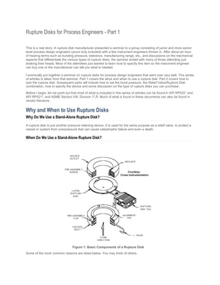
  • 1. Rupture Disks for Process Engineers - Part 1 This is a real story. A rupture disk manufacturer presented a seminar to a group consisting of junior and more senior level process design engineers (yours truly included) with a few instrument engineers thrown in. After about an hour of hearing terms such as bursting pressure, tolerance, manufacturing range, etc., and discussions on the mechanical aspects that differentiate the various types of rupture disks, the seminar ended with many of those attending just shaking their heads. Most of the attendees just wanted to learn how to specify this item so the instrument engineer can buy one or the manufacturer can tell you what is needed. I eventually put together a seminar on rupture disks for process design engineers that went over very well. This series of articles is taken from that seminar. Part 1 covers the whys and when to use a rupture disk. Part 2 covers how to size the rupture disk. Subsequent parts will include how to set the burst pressure, the Relief Valve/Rupture Disk combination, how to specify the device and some discussion on the type of rupture disks you can purchase. Before I begin, let me point out that most of what is included in this series of articles can be found in API RP5201 and API RP5212 , and ASME Section VIII, Division 13 . Much of what is found in these documents can also be found in vendor literature. Why and When to Use Rupture Disks Why Do We Use a Stand-Alone Rupture Disk? A rupture disk is just another pressure relieving device. It is used for the same purpose as a relief valve, to protect a vessel or system from overpressure that can cause catastrophic failure and even a death. When Do We Use a Stand-Alone Rupture Disk? Some of the more common reasons are listed below. You may think of others. Figure 1: Basic Components of a Rupture Disk
  • 2. 1. Capital and Maintenance Savings: Rupture disks cost less than relief valves. They generally require little to no maintenance. 2. Contents will be lost, but who cares? A rupture disk is a nonreclosing device, which means once it opens, it doesn't close. Whatever is in the system will get out and continue to do so until stopped by some form of intervention. If loss of contents is not an issue, then a rupture disk may be the relief device of choice. 3. Benign service: It is preferable that the relieving contents be non-toxic, non-hazardous, etc. However, this is not a requirement when deciding to use, or not use, a stand-alone rupture disk. 4. Rupture disks are extremely fast acting: Rupture disks should be considered first when there is a potential for runaway reactions. In this application, relief valves will not react fast enough to prevent a catastrophic failure. A relief valve may still be installed on the vessel to protect against other relieving scenarios. Some engineers prefer to use rupture disks for heat exchanger tube rupture scenarios rather than relief valves. They are concerned that relief valves won't respond fast enough to pressure spikes that may be experienced if gas/vapor is the driving force or liquid flashing occurs. 5. The system contents can plug the relief valve during relief: There are some liquids that may actually freeze when undergoing rapid depressurization. This may cause blockage within a relief valve that would render it useless. Also, if the vessel contains solids, there is a danger of the relief valve plugging during relief. 6. High viscosity liquids. If the system is filled with highly viscous liquids such as polymers, the rupture disk should seriously be considered as the preferable relieving device. Flow through a relief valve will be very difficult to calculate accurately. Also, very viscous fluid may not relieve fast enough through a relief valve. Cost Comparison Between Comparable Stand-Alone Rupture Disk and Relief Valve Rupture disk manufacturers burst at least two disks per lot before shipping them to a customer. As a consequence even if you want just one rupture disk you will be buying three. Therefore, the first usable rupture disk is comparatively expensive. Also for new installations, each installed rupture disk must be purchased along with a holder. However, the same holder may be used for replacement purchases as long as you buy the exact same rupture disk from the same manufacturer. Below is a capital cost comparison between Continental Disc Corp. (www.contdisc.com) 3" Ultrx Hastelloy C rupture disks with holders and Farris Engineering (www.cwfc.com) 2600 series relief valves, based on a budget estimate in year 2001 dollars.  Table 1: Cost Comparison - Rupture Disk vs. Relief Valve Figure 2: Rupture Disk Mounted on a Vessel
  • 3. Basis: Continental Disc Basis: Farris Engineering 3" Ultrx Hast C Disc = $2,600 for 1st usable disk, then $870 each 3" x 4" Hast C 26KA10-120 = $13,400 3" Ultrx Hast C Holder = $3,300 ea.  TOTAL for one pair = $5,900  TOTAL for three pair = $14,240 TOTAL for three = $40,200 This capital cost comparison will vary considerably with size and material of construction but you get the point. However please note that everything has a value and the loss of contents should be considered in the overall cost difference between a rupture disk and a relief valve. When Do We Use a Rupture Disk-Relief Valve Combination? Rupture disks are often used in combination with and installed just upstream and/or just downstream of a relief valve. You may want to choose the combination option if:  1. You need to ensure a positive seal of the system (the system contains a toxic substance and you are concerned that the relief valve may leak). Application: rupture disk installed upstream of the relief valve. 2. The system contains solids that may plug the relief valve over time. Remember, the relief valve is continuously exposed to the system. Application: rupture disk installed upstream of the relief valve. 3. TO SAVE MONEY! If the system is a corrosive environment, the rupture disk is specified with the more exotic and corrosion resistant material. It acts as the barrier between the corrosive system and the relief valve. Application: rupture disk installed either upstream and/or downstream of the relief valve. Figure 3: Rupture Disk- Relief Valve Combination
  • 4. Below is a capital cost comparison between combination Hastelloy C rupture disks with stainless steel relief valves and three stand-alone Hastelloy C relief valves. Again, this is based on a budget estimate in year 2001 dollars using Continental Disc Corp. rupture disks and holders and Farris Engineering relief valves. Table 2: Cost Comparison for Rupture Disk-Relief Valve Combinations Basis: Continental Disc Basis: Farris Engineering 3" Ultrx Hast C Holder = $3,300 3" x 4" Hast C 26KA10-120 = $13,400 3" Ultrx Hast C Disc = $2,600 for 1st usable disk, then $870 each 3" x 4" SS 26KA10-120 = $4,300 Combination of Hastelloy C Disk and SS Relief Valve Single Installation Total = $10,200 Total for three installations = $27,140 Three stand-alone Hastelloy C relief valves = $40,200 Summary A stand-alone rupture disk is used when: 1. You are looking for capital and maintenance savings 2. You can afford to loose the system contents 3. The system contents are relatively benign 4. You need a pressure relief device that is fast acting 5. A relief valve is not suitable due to the nature of the system contents A rupture disk / relief valve combination is used when: 1. You need to ensure a positive seal of the system 2. The system contains solids that may plug the relief valve over time 3. TO SAVE MONEY! If the system is a corrosive environment, the rupture disk is specified with the more exotic and corrosion resistant material References 1. API (www.api.org) Recommended Practice 520, "Sizing, Selection, and Installation of Pressure-Relieving Device in Refineries, Part 1-Sizing and Selection", 7th Edition (January 2000) 2. API (www.api.org) Recommended Practice 521, "Guide for Pressure-Relieving and Depressuring Systems", 4th Edition (March 1997) 3. ASME (www.asme.org) "Boiler and Pressure Vessel Code, Section VIII, Division 1" (1998)
  • 5. Rupture Disks for Process Engineers - Part 2 Part 1 of this series on rupture disks for Process Engineers covered why you use a rupture disk and when you might want to use this device. This part will discuss how to size the rupture disk. Subsequent parts will include how to set the burst pressure, the Relief Valve/Rupture Disk combination, how to specify the device and some discussion on the type of rupture disks you can purchase. Before I begin, let me point out that most of what is included in this series of articles can be found in API RP5201 and API RP5212 , and ASME Section VIII, Division 13 . Much of what is found in these documents can also be found in vendor literature Sizing Sizing the rupture disk is a two-part procedure. First, determine how much flow the rupture disk needs to pass. Then determine how big it needs to be. How much flow does it need to pass? Answering this question is the same as determining the required relieving rate for the system. There is no difference between determining the relieving rate for a rupture disk and a relief valve. They both require a set pressure (burst pressure for rupture disk), an allowable overpressure, an evaluation and calculation of the required relieving rate for each credible scenario and then choosing the flow rate associated with the worst-case scenario. Determining the controlling relieving rate is a paper in of itself and I will not attempt to get into details here. How Big? There are two recognized methods that can be used to answer this question, the Resistance to Flow Method or the Coefficient of Discharge Method. Resistance to Flow Method The Resistance to Flow Method analyzes the flow capacity of the relief piping. The analysis takes into account frictional losses of the relief piping and all piping components. Calculations are performed using accepted engineering practices for determining fluid flow through piping systems such as the Bernoulli equation for liquids, the Isothermal or adiabatic flow equations for vapor/gas and DIERS methodology for two-phase flow. Piping component losses may include nozzle entrances and exits, elbows, tees, reducers, valves and the rupture disk(note that the rupture disk and its holder are considered a unit). Let me emphasize that in this method, the rupture disk is considered to be just another piping component, nothing more, and nothing less. Therefore the rupture disk's contribution to the over all frictional loss in the piping system needs to be determined. This is accomplished by using "Kr", which is analogous to the K value of other piping components. Kr is determined experimentally in flow laboratories by the manufacturer for their line of products and is certified per ASME Section VIII, Division 13 . It is a measure of the flow resistance through the rupture disk and accounts for the holder and the bursting characteristics of the disk. Below is a list of some models of Continental Disc Corporation rupture disks with their certified Kr values4 . Table 1: Rupture Disks from Continental Disc Corp. Rupture Disk (and holder) Type Media Size Range Kr ULTRX Gas, Liquid 1" - 12" 0.62
  • 6. ULTRX Gas only 1" - 12" 0.36 MINTRX Gas, Liquid 1"- 8" 0.75 STARX Gas, Liquid 1" - 6" 0.38 SANITRX Gas, Liquid 11/2" - 4" 3.18 Â For comparison, the following is a list of some models of Fike rupture disks with their certified Kr values5 . Table 2: Rupture Disks from Fike Rupture Disk (and holder) Type Media Size Range Kr SRX - 1" - 24" 0.99 SRL - 1" - 8" 0.38 SRH - 1 1/2" - 4" 1.88 HO / HOV - 1" - 24" 2.02 PV, CPV, CP-C, CPV-C - 1/2" - 24" 3.50 If at the time of sizing the manufacturer and model of the rupture disk are unknown, there are guidelines to help you choose Kr. API RP5212 recommends using a K of 1.5. However, ASME Section VIII, Division 13 states that a Kr of 2.4shall be used. Which one? Remember that ASME is Code (meaning LAW for the most part) and API is a recommended practice. In addition, as can be seen in the tables above, even ASME may not be as conservative as you may think. Therefore, it is in the engineer's best interest to determine ahead of time the manufacturer and model of the rupture disk that eventually will be purchased. This can be done without knowing the exact size, as Kr is more manufacturer and model specific than size specific (see above tables). If a number of manufacturers are on the allowable purchase list, then at the very least choose the most likely models you would buy from each manufacturer and use the largest Kr from that list. This will be a significantly better guess than just using guidelines. Once the piping system is laid out and all the fitting types are known, including the rupture disk, the engineer can proceed with the calculations in the following manner (presented here as a suggestion, there are many ways to do it). 1. Known are the two terminal pressures, these being the relieving pressure (upstream) and the downstream pressure (a knock-out pot, atmosphere, etc.).
  • 7. 2. Also known are the fluid properties and required relieving rate (the flow the rupture disk needs to pass). 3. Choose a pipe size. This will be the size to use for all components, including the rupture disk. 4. For vapor/gas or two-phase flow, use one of the accepted calculation methods to determine the maximum flow through the system. The maximum flow through the system is commonly known as critical flow or choked flow. For liquids, use the Bernoulli equation to calculate the flow that will balance the system pressure losses. 5. Per ASME Section VIII, Division 1, multiply this flow by 0.9 to take into account inaccuracies in the system parameters. Compare the adjusted calculated flow to the required relieving rate. If it is greater, then the calculation is basically done. However, the next smaller line size should also be checked to make sure the system is optimized; you want the smallest sized system possible. If the adjusted calculated flow is less than the required relieving rate, the pipe is too small, choose a larger size and repeat the calculations. Why not just choose a large Kr? Isn't that more conservative? Many times, relief is not to atmosphere but to some downstream collection and treatment system, e.g. knockout drums and flares or thermal oxidizers. These are more often than not specified at a time period in the design that predates the actual purchase of the rupture disk. The flow used to size this equipment will be based on the capacity of your relief system as determined above. If the rupture disk contributes a significant portion of the frictional losses to the system, a fictitiously large Kr might result in an oversized piping system. Sounds all right on the surface but once the actual rupture disk is chosen, the calculation must be repeated with the "real" Kr and this may be a much lower value than originally used. More fluid will flow through the system than previously determined because there will actually be less resistance to flow. The result is that the downstream processing equipment may have been undersized. The opposite is also true. An initial guess of a fictitiously small Kr might ultimately result in oversized downstream equipment and the excessive expenditure of a significant amount of money. Atmospheric discharge must also be similarly analyzed because the flow capacity determined after rupture disk selection may have a major impact on the emissions reported for permitting if they were based on the initial value of Kr. Coefficient of Discharge Model The second calculational method is the Coefficient of Discharge Method. The rupture disk is treated as a relief valve with the flow area calculated utilizing relief valve formulas and a fixed coefficient of discharge, ‘Kd', of 0.62. This method does NOT directly take into account piping so there are restrictions in its use. These restrictions are known as the "8 & 5 Rule" which states that in order to use this method to size the rupture disk ALL of the following four conditions MUST be met3: The rupture disk must be installed within 8 pipe diameters of the vessel or other overpressure source. 1. The rupture disk discharge pipe must not exceed 5 pipe diameters. 2. The rupture disk must discharge directly to atmosphere. 3. The inlet and outlet piping is at least the same nominal pipe size as the rupture disk. A sketch of the "8 & 5" rule starting with a 2" nominal sized pipe is shown at the below. The flow area calculated with this method is called the Minimum Net Flow Area or MNFA. The MNFA is the rupture disk's minimum cross
  • 8. sectional area required to meet the needed flow. This is not the area (and thus the size) you specify. Just like a pipe with a nominal size and an actual inside diameter, the rupture disk has a nominal size and an actual Net Flow Area or NFA. The rupture disk purchased must have a NFA equal to or greater than the MNFA. The manufacturer publishes the NFA for every rupture disk model and size they sell. The NFA also accounts for bursting characteristics of the disk and the holder. Below is a list of some Continental Disc Corporation rupture disks with their NFA4 . Â Table 3: Continental Disc Corp Disks with NFA Rupture Disk (and holder) Type Nominal Size, inches NFA, in2 ULTRX 1-1/2" 2.04 ULTRX 3" 7.39 SANITRX 1-1/2" 1.18 SANITRX 3" 5.49 Once the actual NFA of the rupture disk is determined, the calculations must be repeated, basically for the same reasons discussed above for the Resistance to Flow Method. Why I Don't Like the Coefficient of Discharge Model Figure 1: Diagram Showing the "8 & 5" Rule
  • 9.  It's too restrictive! During the basic design phase of a project, actual piping configuration is unknown. You may think you are within the "8 & 5" rule at first but may not be when the final details are worked out. Remember, the "5" means 5 pipe diameters. For a 3" line, that is only a nominal 15". For a 6' vertical vessel with a rupture disk discharge being piped to a drain hub on the floor, the 15" maximum length is exceeded without even thinking.  Using the Resistance to Flow Method is valid for all cases. All sizing calculations can be standardized.  The Kr used in the Resistance to Flow Method is obtained by actual flow data for a given model of rupture disk and holder. Its use will provide a much more accurate calculation. The 0.62 coefficient of discharge used in the Coefficient of Discharge Method is very general and independent of rupture disk manufacturer model and type, holder, disk bursting characteristics and flow restrictions of the total relief system.  Two-phase flow can be a major concern when using this method. The coefficient of discharge was established mainly for true vapors. Its application to liquids is questionable and its application to two-phase flow is totally fictitious. Granted, for the Resistance to Flow Method the Kr is not particularly applicable to two-phase systems either but one can easily compensate for this in the system calculations. Also, the rupture disk is only a part of an entire piping system and its overall contribution to the system frictional losses may not be greatly significant. Therefore, errors in Kr may not be very significant. In the Coefficient of Discharge Method, it is the only device considered. If the coefficient of discharge is grossly in error, the MNFA calculated will also be grossly in error.  The same argument can be made for highly viscous liquid systems such as polymers. In Summary  Obtain the required relieving rate using good sound "what can go wrong" scenario analysis.  Use the Resistance to Flow Method to calculate the size of the rupture disk (use the Coefficient of Discharge Method if you really must and you fall within the "8 & 5" rule).  For the Resistance to Flow Method, try to choose the manufacturer and model of rupture disk you intend to purchase ahead of time or at least have a list of acceptable manufacturers and a good idea of the model you intend to use from each.  For the Resistance to Flow Method use the ASME Kr value of 2.4 if you have no idea who the manufacturer(s) will be at the time of sizing. References 1. API (www.api.org) Recommended Practice 520, "Sizing, Selection, and Installation of Pressure-Relieving Device in Refineries, Part 1-Sizing and Selection", 7th Edition (January 2000) 2. API (www.api.org) Recommended Practice 521, "Guide for Pressure-Relieving and Depressuring Systems", 4th Edition (March 1997) 3. ASME (www.asme.org) "Boiler and Pressure Vessel Code, Section VIII, Division 1" (1998) 4. Continental Disc Corporation (www.contdisc.com), CertiflowTM Catalogue 1-1112 5. Fike (www.fike.com), Technical Bulletin TB8104, December 1999 6. Another good rupture disk manufacturer to investigate would be Oseco (www.oseco.com). 7. A good reference source for calculating flow through the system for liquids and gas/vapors is CRANE Technical Paper 410, "Flow of Fluids Through Valves, Fittings, and Pipe" 8. A great source and one that I feel should be the bible on two-phase flow is: Leung, J.C. "Easily Size Relief Device and Piping for Two-Phase Flow", Chemical Engineering Progress, December, 1996
  • 10. Rupture Disks for Process Engineers - Part 3 Part 1 of this series on rupture disks for Process Engineers covered why you use a rupture disk and when you might want to use this device. Part 2 discussed how to size the rupture disk. In this part, I will cover how to set the burst pressure. Subsequent parts will include temperature and backpressure affects, the Relief Valve/Rupture Disk combination, how to specify the rupture disk and some discussion on the type of rupture disks you can purchase. Before I begin, let me point out that most of what is included in this series of articles can be found in API RP5201 and API RP5212 , and ASME Section VIII, Division 13 . Much of what is found in these documents can also be found in vendor literature. Problem 1. What is the maximum allowable specified burst pressure? 2. What should the expected stamped (rated) burst pressure of the rupture disk be? 3. At what pressure(s) can we expect the delivered rupture disk to actually burst at? 4. What is the maximum allowable operating pressure in the vessel? All these questions must be considered in order to properly set the burst pressure of a rupture disk. What is the Maximum Allowable Specified Burst Pressure? Burst Pressure What do we mean by burst pressure? This is the pressure at which the rupture disk will open or burst. It is analogous to the set pressure of a relief valve and is specified by the process engineer. Design Pressure To find the maximum allowable specified burst pressure, the process engineer first needs to define a vessel design pressure. The design pressure is an arbitrary value above the vessel maximum operating pressure. One guideline used by many process design engineers is to increase the maximum operating pressure by 25 psig or 10% whichever is greater. For example, if the maximum operating pressure is 70 psig, then 25 psig should be added to arrive at the design pressure since 10% is only 7 psig. The design pressure would then be set at a nice round 100 psig. Other criteria to determine design pressure may be used but I recommend that the margins never be less than what I described above (the reason will become apparent later). Maximum Allowable Working Pressure (MAWP) The next step is to determine the Maximum Allowable Working Pressure (MAWP) of the vessel. A vessel specification stating design pressure, the coincident design temperature and other parameters is sent to the manufacturer. The manufacturer performs a series of calculations utilizing these parameters, amongst others, to determine material thickness for use in vessel fabrication. A standard material thickness (greater than or equal to what was calculated) is chosen. With the actual material thickness known, the true MAWP is calculated. The vessel design documents are then stamped (certified) at this pressure in accordance with code. However, for one reason or another, the MAWP calculation is not always done and the vendor will just stamp the vessel at the specified design pressure. The Maximum Allowable Specified Burst Pressure So, what is the maximum allowable specified burst pressure? Theoretically it is the MAWP. However, rupture disks are typically specified during basic engineering, which is performed way before the vessel is mechanically designed. This, combined with the fact that the true MAWP may never really be known (as mentioned above), the maximum allowable specified burst pressure will more typically be the vessel's design pressure. Note if the rupture disk is to be used in conjunction with another relief device to fulfill the total required relieving capacity, the maximum allowable specified burst pressure could be 5% or even 10% greater than the design pressure (or MAWP). See ASME Section VIII, Division 1 paragraphs UG-125 and UG-134.
  • 11. Also note that the specified burst pressure can be lower than the maximum allowable. Indeed, this is often the case if the rupture disk is used to protect reactor vessels against over pressure due to run-away reactions. Stamped Burst Pressure What should the expected stamped (rated) burst pressure of the rupture disk be? What do we mean by "stamped or rated" burst pressure? Per code, the rupture disk vendor must provide a tag containing, amongst other things, the rated or what is typically called the stamped burst pressure. This is a guaranteed value so the user knows (within an allowable tolerance; more on this later) the exact bursting pressure of the rupture disk. Also this stamped burst pressure must never exceed the design pressure (or MAWP); except for the special case mentioned above. So, the rupture disk vendor stamps the disk with the burst pressure specified by the process engineer? Not necessarily! Manufacturing Range (MR) Figure 1: Graphical Representation of the Manufacturing Range A rupture disk is made out of a sheet of material, e.g. stainless steel, high alloys, ceramics, etc. Like all things in this world, this sheet of material is not perfect. To quantify the inaccuracies in sheet material thickness, the vendor uses what is called the Manufacturing Range (MR). Â Figure 2A: Specified and Stamped Burst Pressure
  • 12. The MR is expressed as ±% of the specified burst pressure. It determines the highest pressure above the specifiedburst pressure or the lowest pressure below the specified burst pressure that the disk can be stamped at. This is shown graphically in Figure 1. Figure 1 shows the two extremes, a MR of ± 0% and a MR of ± some value%. Note that other combinations may be used such as + 0% and - some value% or - 0% and + some value%. Let's look at an example. If the specified burst pressure is 100 psig with a MR of ± 0%, the stamped or rated burst pressure will be 100 psig (see Figure 2A). However, if the MR is +5% and - 10%, the disk can be delivered with a stamped burst pressure of 105 psig, 90 psig or anywhere in between (see Figure 2B). That's right, if the MR is anything but ± 0%, the user won't know the stamped burst pressure until the rupture disk is ready for shipment! Figure 2B: Differences in Specified and Stamped Burst Pressures Do you see anything wrong with this rupture disk as specified? Remember, the stamped or rated burst pressure must never exceed the vessel's design pressure or MAWP (assumes a single device, no special cases). Since the specified burst pressure is the design pressure, this particular rupture disk is not acceptable because the delivered rupture disk may have a stamped burst pressure of 105 psig or 5 psig greater than design! How can we avoid this problem? There are a number of ways. The process engineer specifies the Manufacturing Range, not the manufacturer. You can ask for any range within the capability of fabrication including ± 0%. Considering the potential problems, why specify anything other than ± 0%? Cost. A MR of +5% and -10% can save as much as 40% off the cost of a similar rupture disk with a MR of ± 0%. Even if you demand +0% (which you should), you can still realize some cost savings if a stamped burst pressure lower than specified is acceptable (not always a good idea as will be discussed later). Note that code only affects the upper stamped limit, not the lower. Another way to avoid the potential violation of code and still get a cheaper rupture disk is to specify a burst pressure that will be lower than the vessel design pressure. Thus, when the MR is added the stamped burst pressure will not exceed the design pressure. The maximum allowable specified burst pressure could be determined in the following manner: Pspec_max = (DP) - (+MR/100) x (Pspec_max) Where DP = Design pressure So:
  • 13. Pspec_max = (DP) / [1+(+MR)/100] Since DP = 100 psig and the upper value of MR = +5%, Pspec_max = 100 /[1+(+5/100)] = 100/(1+0.05) = 100/1.05 = 95.2 psig This rupture disk would be specified with a burst pressure no higher than 95.2 psig while the stamped burst pressure may be as high as 100 psig. Note that the standard Manufacturing Range for most manufacturers is ± 0% and this is reflected in the base price you will be quoted. Where Will the Disk Burst? At what pressure(s) can we expect the delivered rupture disk to burst at? Trick question? The answer should be the stamped burst pressure. But again the world isn't perfect. Burst Tolerance  The Manufacturing Range is applied to the specified burst pressure but there is yet another unknown due to imperfections in the material used to fabricate the rupture disk. This is accounted for in the burst tolerance. Burst tolerance is applied to the stamped burst pressure and is set by code. For stamped burst pressures of 40 psig and lower, the burst tolerance is ± 2 psi. For stamped burst pressures above 40 psig, the burst tolerance is ± 5%. Let's look at the examples again but apply the burst tolerance. For this discussion, I'm changing the specified burst pressure for the case of a rupture disk with a Manufacturing Range of +5% and -10% to 95.2 psig (see Figure 3B) so the stamped burst pressure can't exceed code. The important thing to notice is that in both Figures 3A and 3B, the upper limit of the stamped burst pressure is equal to the design pressure but the maximum bursting pressure is 105 psig, or 5 psig over design pressure. Unlike thestamped burst pressure, which by code cannot exceed the design pressure (or MAWP), the maximum expected burst pressure can if it is caused by the burst tolerance. Figure 3A: Burst Tolerance
  • 14. Figure 3B: Specified, Stamped, and Maximum Burst Maximum Allowable Operating Pressure What is the maximum allowable operating pressure in the vessel? Up to now, the discussions focused on the upper limit of the stamped burst pressure because this is governed by code. But the lower limit is extremely important to consider as well because of the possible affect it has on the maximum allowable operating pressure in the vessel. Operating Ratio (OR) The operating ratio is defined as the ratio of the maximum operating pressure to the lowest stamped burst pressure. The OR is used to protect against premature bursting of the rupture disk. If the operating pressure is too close to the lowest stamped burst pressure, or the system pressure cycles (pressure rises and falls during operation) too close to the stamped burst pressure, the material will fatigue and can eventually loose its structural integrity. This is a classic reason for premature bursting of a rupture disk. The manufacturer publishes the Operating Ratio for every rupture disk model they sell. For example, the Continental Disc Corporation's ULTRX rupture disk has an operating ratio of 90%4 . This means the system pressure can operate to within 90% of the lowest stamped burst pressure without the fear of premature bursting. However, it's always best to operate as far away from the lowest stamped burst pressure as you can to avoid material fatigue. From Figure 3B above, the lower limit or minimum stamped burst pressure is 85.7 psig: Pstamped_min = (Pspec) - ABS [(-MR/100)] x (Pspec) Where ‘ABS' stands for Absolute Value. So: Pstamped_min = (Pspec) x {1- ABS [(-MR/100)]}
  • 15. Since Pspec = 95.2 psig and the lower value of MR = -10%, Pstamped_min = 95.2 x {1 - ABS [(-10/100)]} = 95.2 x {1-ABS [(-0.1)]} = 95.2 x (1-0.1) = 95.2 x 0.9 = 85.7 psig Therefore based on an OR of 90%, the maximum allowable operating pressure should not be greater than: Pop = Pstamped_min x OR = 85.7 x 0.9 = 77 psig. Since our discussions have been based on a maximum operating pressure of 70 psig, this rupture disk is acceptable. But note that this 10% cushion exists only because of the design pressure margin used (25 psig). Had the margin been less, say only 10%, the rupture disk we would want to use would be unacceptable. How to avoid this problem?  Set the design pressure appropriately  Choose a rupture disk with a MR of ± 0%  Choose a rupture disk with a OR of 90% (they don't really go much higher) There is one more point to consider. Although I have never seen any mention of checking the maximum allowable operating pressure against the minimum expected burst pressure (arrived at by taking into account the burst tolerance), I think it only makes good engineering sense to do so. After all, if the disk can burst at this lower pressure, one certainly does not want to operate too close to it! Getting back to our question, what is the maximum allowable operating pressure in the vessel? In this case, it is 77 psig. Summary  What is the maximum allowable specified burst pressure? - Design Pressure or MAWP if the rupture disk is the only relief device OR - For special cases, 105% (or even 110%) of design pressure or MAWP if the rupture disk is a secondary device   What should be the expected stamped (rated) burst pressure of the rupture disk? - As specified by the process engineer for a Manufacturing Range of ± 0% OR - As specified by the process engineer but could be adjusted per the Manufacturing Range if other than ± 0%  At what pressure(s) can we expect the delivered rupture disk toactually burst at? - ± 5% of stamped burst pressure for stamped pressures greater than 40 psig OR - ± 2 psi for stamped pressures 40 psig and lower  What is the maximum allowable operating pressure in the vessel? - Specified by the process engineer based on operating need but must be checked against the Operating Ratio of the rupture disk - I strongly suggest you also check against the minimum expected burst pressure as well.
  • 16.  Manufacturing Range is applied to the specified burst pressure  Burst Tolerance is applied to the stamped burst pressure  Set the design pressure appropriately  Choose a rupture disk with a MR of ± 0%  Choose a rupture disk with a OR of 90% WARNING! Don't go running out and specifying a rupture disk just quite yet! We still need to consider the affects of temperature and backpressure and the relief valve-rupture disk combination. References 1. API (www.api.org) Recommended Practice 520, "Sizing, Selection, and Installation of Pressure-Relieving Device in Refineries, Part 1-Sizing and Selection", 7th Edition (January 2000) 2. API (www.api.org) Recommended Practice 521, "Guide for Pressure-Relieving and Depressuring Systems", 4th Edition (March 1997) 3. ASME (www.asme.org) "Boiler and Pressure Vessel Code, Section VIII, Division 1" (1998) 4. Continental Disc Corporation, ULTRX ® Catalogue 3-2210-3 Â
  • 17. Rupture Disks for Process Engineers - Part 4 Part 1 of this series on rupture disks for Process Engineers covered why you use a rupture disk and when you might want to use this device. Part 2 discussed how to size the rupture disk. Part 3 discussed how to set the burst pressure. In this part, I will discuss how temperature and backpressure affects the rupture disk design. Subsequent parts will include the Relief Valve/Rupture Disk combination, how to specify the rupture disk and some discussion on the type of rupture disks you can purchase. Before I begin, let me point out that most of what is included in this series of articles can be found in API RP5201 and API RP5212 , and ASME Section VIII, Division 13 . Much of what is found in these documents can also be found in vendor literature. Temperature and Backpressure Considerations In Part 3, I discussed how to set the burst pressure of the rupture disk. However, the discussion is not complete without considering the effects of temperature and backpressure on the bursting pressure. Temperature The rupture disk manufacturer uses both the specified burst pressure and the specified temperature when designing and stamping the disk. (In this instance, I use the term design to mean arriving at the correct burst pressure, not mechanical integrity). However, it is more than likely that the temperature of the rupture disk will not be at the specified temperature when it is called into service. Why is this so? The temperature most commonly specified is that of the relieving fluid coincident with the burst pressure, i.e. relieving conditions. Sounds logical, but remember that the disk is continuously exposed to the process stream for hours, days, weeks or even months before it may ever be needed. Or, the disk may be exposed to ambient conditions. Therefore, expect the disk temperature to be approximately equal to its environment during normal operation of the system. When a process upset occurs, system pressure rises until it reaches relief (burst). The temperature of the relieving fluid also rises per thermodynamics. However, the time interval between normal system operation and relief is usually so small that the rupture disk's temperature hardly has time to come to equilibrium with the higher process fluid temperature. Therefore the disk can actually be colder than it's specified temperature. The affects? In general, burst pressure varies inversely with temperature. For some rupture disks, the burst pressure can be as much as 15 psi greater than stamped if the actual temperature is 100o F lower than specified, e.g. a disk specified with a burst pressure of 350 psig at a temperature of 400o F will actually burst at 365 psig if its temperature is only 300o F4 . This doesn't sound like a big difference but if 350 psig were the design pressure (or MAWP) of the vessel, then a burst pressure of 365 psig would be in violation of code (LAW). The opposite is also true. A disk at a temperature hotter than specified when called into service will burst at a pressure lower than stamped. Although this is considered to be the more conservative approach because code can't be violated and there is no risk of catastrophic failure of the vessel, specifying too low of a temperature can lead to the not so desirable action of premature bursting. The bottom line is that the specified burst temperature must be carefully considered. Specify the lowest temperature at the time the disk is expected to burst. Consider that this might be the normal process operating temperature or even ambient rather than the calculated relieving temperature. Note that different materials and different types of rupture disks have different sensitivities to temperature. This is an excellent topic of discussion for your rupture disk manufacturer! Backpressure A rupture disk is actually a differential pressure device where the specified burst pressure is equal to the difference between the desired upstream pressure (vessel) at the time of rupture disk burst and the downstream pressure (backpressure): Pburst = Pvessel - Pbackpressure
  • 18. Or alternately the desired upstream pressure (vessel) at the time of rupture disk burst is equal to the sum of the specified burst pressure and the downstream pressure (backpressure): Pvessel = Pburst + Pbackpressure Either way, it is apparent that the vessel pressure at the time the rupture disk bursts (commonly called the relief pressure) is directly dependent on backpressure. When discussing relief systems, three types of backpressure are considered, these being constant, built-up and superimposed. Figure 1A: Single Vessel, Single Rupture Disk Protection, Expected Constant Back pressure = 0 psig Figure 1A shows a system comprised of a single vessel protected by a single rupture disk with a specified burst pressure of 100 psig. The relief pipe discharges a few inches below the liquid surface in a knockout drum, which is held at a constant 0-psig pressure. Therefore, the rupture disk sees a constant (fixed) backpressure of 0 psig. If the vessel were to go into relief, this disk will burst at 100 psig and the vessel relief pressure will be 100 psig (100 + 0 = 100). Figure 1B: Single Vessel, Single Rupture Disk Protection, Actual Constant Back pressure >Â Expected Figure 1B is the same system however for some reason the pressure in the knockout drum is to be maintained at 5 psig instead of 0 psig. The constant (fixed) backpressure against the rupture disk is now 5 psig. If the vessel were to go into relief, the rupture disk would still burst at 100 psig but the vessel relief pressure would now be 105 psig (100 + 5 = 105) rather than the 100 psig expected. This situation could result in a violation of code3 .
  • 19. Figure 1C: Single Vessel, Single Rupture Disk Protection, Actual Constant Back pressure <Â Expected Figure 1C is again the system however for some reason the pressure in the knockout drum is to be maintained at -5 psig instead of 0 psig. The constant (fixed) backpressure against the rupture disk is now -5 psig. If the vessel were to go into relief, the rupture disk would still burst at 100 psig but the vessel relief pressure would now be only 95 psig (100 + (- 5) = 95) rather than the 100 psig expected. There is no particular safety concern here because the vessel can't over pressure. However, the Operating Ratio is affected, which can result in a very premature bursting of the rupture disk. For the vessel relief pressure to be specified correctly, the rupture disk vendor must be told the constant back pressure so that the rupture disk can be designed accordingly. And, if you truly want the vessel relief pressure to be at a specific value then the "constant" backpressure given to the vendor must be maintained at all times. The key point is that during design, be aware of the constant backpressure and ensure that the vessel relief pressure will not violate code or affect normal operation. Â
  • 20. Figure 2A: Two Vessel System - Common Discharge Built-up and Superimposed Back Pressures Now let's look at the system shown in Figure 2A. A second vessel with a single rupture disk also specified to burst at 100 psig is added in close proximity to the first vessel. The relief piping from the two vessels is tied into a common header before discharging into a knockout drum in the same manner as before, the tie-in occurs near the vessels. At the exact moment Vessel No. 2 goes into relief and its rupture disk bursts, Vessel No. 2's relief pressure is 100 psig due to the constant 0-psig backpressure as described above. After the disk bursts, flow is established causing pressure to build up in the piping system (built-up backpressure). The amount of built-up backpressure is dependent on the system pressure drop and possibly even the phenomenon of choked flow. For the purpose of this discussion, assume total built-up backpressure is 10 psig after rupture disk No. 2 bursts and the pressure in Vessel No. 2 is about 110 psig. Because of the proximity of the two discharge pipes and vessels, the pressure near vessel No. 1 will also be at about 110 psig. This pressure, which is exerted or imposed onto rupture disk No. 1, is called the superimposed backpressure with respect to rupture disk No. 1. If vessel No. 1 were to go into relief shortly afterwards, then for rupture disk No. 1 to burst, the pressure in vessel No. 1 would have to build to about 210 psig (100 + 110)!  This is clearly unacceptable!! One solution to this potentially catastrophic condition is to separate the two relief lines so that one cannot directly affect the other (see Figure 2B below). Of course the answer may very well be that this is not an application for rupture disks but for relief valves! The key point is, avoid combining multiple rupture disk piping into a common relief header.
  • 21. Figure 2B: Two Vessel System - Common Discharge Built-up and Superimposed Back Pressures Note that built-up backpressure is variable and depends on the relieving rate, which is a function of the relieving scenario. Also, built-up backpressure has no affect on the vessel's relief pressure for systems such as those shown in Figure 1 above. Built-up backpressure is the result of fluid flow only and there is no fluid flow before the rupture disk bursts. Therefore, along with the Manufacturing Range (MR), Operating Ratio (OR) and Burst Tolerance (BT) that were discussed in Part 3, the process design engineer must also strongly consider the backpressure (especially superimposed backpressure) when specifying the rupture disk. In Summary  Generally, burst pressure varies inversely with temperature so the specified burst temperature must be carefully considered. - Specify the lowest temperature at the time the disk is expected to burst. - Different materials and different types of rupture disks have different sensitivities to temperature effects.  The rupture disk is a differential pressure device. - The specified burst pressure is a value equal to the vessel relief pressure minus the backpressure. - The vessel relief pressure equals the specified burst pressure plus the backpressure.
  • 22.  There are three types of backpressure to consider, these being constant, built-up and superimposed. - Constant backpressure is the pressure in the system that does not vary. It is generally a predictable component of the superimposed backpressure. - Built-up backpressure is the pressure created in the system as a result of fluid flow. It is a varying component of the superimposed backpressure. - Superimposed backpressure is the total pressure exerted (imposed) on the rupture disk by other sources. It is a variable that directly increases or decreases a vessel's relief pressure. It can also interfere with the expected operating ratio of the disk.  Do not pipe multiple vessel relief systems into a common header; keep the piping separate. However, the individual piping may go to a common disposal system.  Along with the Manufacturing Range (MR), Operating Ratio (OR) and Burst Tolerance (BT), the process design engineer must also consider backpressure when specifying the rupture disk. References 1. API (www.api.org) Recommended Practice 520, "Sizing, Selection, and Installation of Pressure-Relieving Device in Refineries, Part 1-Sizing and Selection", 7th Edition (January 2000) 2. API (www.api.org) Recommended Practice 521, "Guide for Pressure-Relieving and Depressuring Systems", 4th Edition (March 1997) 3. ASME (www.asme.org) "Boiler and Pressure Vessel Code, Section VIII, Division 1" (1998) 4. Nazario, F. N., "Rupture Discs, A Primer", Chemical Engineering Magazine, June 20, 1988.
  • 23. Rupture Disks for Process Engineers - Part 5 Part 1 of this series on rupture disks for Process Engineers covered why you use a rupture disk and when you might want to use this device. Part 2 discussed how to size the rupture disk. Part 3 discussed how to set the burst pressure. Part 4 discussed how temperature and backpressure affects the rupture disk specification and the relief pressure in the system. In this part, I will discuss the Relief Valve/Rupture Disk combination. Subsequent parts will include how to specify the rupture disk and some discussion on the type of rupture disks you can purchase. Before I begin, let me point out that most of what is included in this series of articles can be found in API RP5201 and API RP5212, and ASME Section VIII, Division 13. Much of what is found in these documents can also be found in vendor literature. For the relief valve/rupture disk combination (Figure 1), rupture disk sizing is totally dependent on relief valve sizing, regardless whether the rupture disk is installed upstream or downstream of the relief valve. Consequently, the discussion at this point must turn to a brief overview of relief valves. Relief Valve Sizing Overview Basically, the relief valve is treated as an ideal nozzle, i.e. isentropic (constant entropy) flow. A correction factor, the coefficient of discharge, is incorporated into the sizing equations to take into account the fact that this is not an ideal nozzle. The sizing equations themselves can be found in one or more of the references presented at the end. To size a relief valve, the process engineer first determines therequired relieving flow and fluid properties based on an analysis of "what can go wrong" scenarios. The flow and properties are then inserted into the appropriate sizing equation to arrive at a calculated relief valve area. If this were a stand-alone relief valve, the process engineer would use this calculated relief valve area to choose an actual relief valve from a vendor catalog. But since this is a discussion of the relief valve/rupture disk combination, adjustments should be made to the calculated relief valve area before the actual relief valve is chosen. The Rupture Disk Affect The presence of a rupture disk acts to de-rate the relief valve capacity. This de-rating factor, called the Combination Capacity Factor (CCF), may or may not be implicitly included in the sizing formulas. Nevertheless, it is the responsibility of the process engineer to apply the factor correctly.  Figure 1: Relief Valve/Rupture Disk Combination
  • 24. The Combination Capacity Factor (CCF) The Combination Capacity Factor (CCF) is a calculated value that is derived from data obtained during certified capacity testing of the stand-alone relief valve and the relief valve/rupture disk combination. The manufacturer first determines the capacity of the stand-alone relief valve. The rupture disk is then added, close-coupled, to the inlet of the relief valve and the capacity of the relief valve/rupture disk combination is determined. Finally, the CCF is calculated as the ratio of the relief valve/rupture disk combination capacity to the stand-alone relief valve capacity: CCF = Flow Combination Capacity / Flow Stand-Alone Relief Valve Capacity Below is a list of certified Combination Capacity Factors for the Continental Disc Corporation model ULTRX ® rupture disks with the Crosby JOS/JBS Relief Valve 4 . Table 1: CCF's from Continental Disk Rupture Disk Size Burst Pressure, psig Material CCF 1" 60 minimum Nickel 0.981 Stainless Steel 0.980 3" 30 - 59 Nickel 0.981 Stainless Steel 0.984 For comparison, the following is a list of certified Combination Capacity Factors for the Fike model MRK rupture disk with the Crosby JOS/JBS Relief Valve5 . Table 2: CCF's from Fike Rupture Disk Size Burst Pressure, psig Material CCF 1" 60 minimum Nickel 0.977 Stainless Steel 0.967 3" 35 minimum Nickel 0.995 Stainless Steel 0.982
  • 25. Note that the CCF is a certified value and is only good for the design of the relief valve and the rupture disk that are used in the test. Since it is in the best interest of the rupture disk manufacturer to certify as many of their rupture disk designs with as many different types of relief valve designs as possible, it is typical for the rupture disk manufacturer to perform this testing and reporting of the CCF. The certified CCF will always be less than or equal to 1.0. If the manufacturer and/or model of the rupture disk and relief valve are unknown at the time of sizing, or there is no published value for a relief valve/rupture disk combination, ASME3 requires that the CCF is not to exceed 0.9. Applying the CCF API Recommended Practices 5201 shows the CCF as being applied to the denominator of the relief valve sizing equation. For example, a typical sizing equation for gas relief might look something like this: Eq. (1) Where: W = required relieving rate, mass flow TÂ = relieving temperature, absolute ZÂ = compressibility factor M = molecular weight C = gas constant = a function of (Cp / Cv) Cp = specific heat at constant pressure (consistent units) Cv = specific heat at constant volume (consistent units) Kd = coefficient of discharge, dimensionless Kb = backpressure correction factor, dimensionless P1 = relief pressure (absolute) Note that this is the same as dividing the calculated, stand-alone relief valve area by the CCF to arrive at a required relief valve area for the combination unit: Eq. (2) And: A required = A calculated / CCF Eq. (3) The process engineer will use this required relief valve area as the basis for choosing a relief valve from the vendor catalog. One important thing to note is that the preceding methodology is not a requirement of code (ASME). ASME only requires that the stand-alone relief valve's certified flow capacity be de-rated by the CCF: Flow Combination Certified Capacity = Flow Stand-Alone Relief Valve Certified Capacity x CCF Eq. (4) There is no mention of using the CCF to arrive at a relief valve area. Indeed, prior to the most recent edition of API RP5201 , the sizing equations themselves did not explicitly include a correction factor for the relief valve/rupture disk combination. Note also that de-rating the certified flow capacity is only required if the rupture disk is installed upstream of the relief valve, it is not required if installed downstream of the relief valve.
  • 26. Certified (Rated) Capacity As stated above, each stand-alone relief valve will have associated with it a certified flow capacity, which is a function of both the relief valve area and the set pressure. This flow is determined by certified capacity testing procedures and is to be considered the guaranteed flow rate that can be achieved through the particular valve. With very few exceptions, this flow is used in determining both the relief valve inlet and outlet (tail pipe) line sizes. The certified flow capacity is officially stamped on the relief valve documentation. For relief valve/rupture disk combinations, the de- ratedcertified flow will also be stamped on the documentation. Although the relief valve is chosen based on area, the process engineer must still ensure that the certified flow capacity is greater than or equal to the required relieving flow: Certified Flow Capacity ³ Required Relieving Flow If it is not, the chosen relief valve is too small. For the relief valve/rupture disk combination, the required relieving flow would be compared to the de-rated or combination certified flow capacity: Combination Certified Flow Capacity ³ Required Relieving Flow Relief Valve Sizing Inlet Line The relief valve inlet line is defined as the piping between the inlet to the system (e.g. the inlet to a vessel nozzle) and the relief valve inlet flange. Sizing this inlet line is a trial-and-error procedure. First, the process engineer chooses a line size using guidelines set by code; code requires that the flow area of the line and all associated piping components be at least equal to the relief valve inlet flow area. Then, using accepted fluid flow equations (e.g. Darcy for single phase liquid or gas/vapor and DIERS for two phase) and the certified flow capacity of the stand-alone relief valve the non-recoverable frictional losses in the line are determined. The sum of all non-recoverable losses should be less than 3% of the relief valve set pressure, this criteria is commonly referred to as the 3% Rule. In general, if the 3% Rule is exceeded then the chosen line size is too small. Outlet Line (Tail Pipe) Sizing Overview The sizing of the tail pipe is done in a similar manner to that outlined above for the inlet line. The process engineer first chooses a pipe size. Then, using accepted fluid flow equations (e.g. Darcy for liquids, Isothermal or Adiabatic for gas/vapor and DIERS for two-phase) and the same certified flow capacity as used for the inlet line, a built-up (variable) backpressure is calculated. The built-up backpressure is converted to a percentage of the relief valve set pressure and is then compared to some maximum value that is set by the particular relief valve manufacturer. For example, tail pipes on conventional style relief valves would be sized such that the built-up (variable) backpressure does not exceed 10% of the relief valve set pressure. For balanced bellows style relief valves, tail pipes would be sized such that the built-up (variable) backpressure does not exceed 30% to 55% of the relief valve set pressure, depending on manufacturer. If the calculated percentage is less than or equal to these maximums, the line size is acceptable. If the calculated percentage is greater, the line size may or may not be acceptable. This is because the only requirement of code is that the built-up backpressure does not affect the relief valve's ability to relieve the required amount of flow necessary to protect the system. Built-up backpressures greater than the stated maximums require a de-rating of the relief valve based on curves developed by the manufactures. As long as the de- rated valve can still relieve the required relieving flow, the line size chosen is acceptable. If not, then the line is too small. Now that we've sized the relief valve in the relief valve/rupture disk combination, what about sizing the rupture disk? Actually, we already did! The Rupture Disk Sizing You will recall from Part 2 of this series that sizing the rupture disk is a two-part procedure. First, determine how much flow the rupture disk needs to pass. Then determine how big it needs to be.
  • 27. Both criteria have been met with the relief valve sizing. How much flow? The rupture disk must be able to pass thecertified flow capacity of the relief valve. How big? The rupture disk must be big enough so that its contribution to the frictional losses does not pose a significant impact on the ability of the relief valve to protect the system. For a rupture disk installed in the inlet line, the rupture disk's net flow area must be at least equal to the relief valve inlet flow area; it may be larger. Also, its contribution to the non-recoverable frictional losses should be minimal so as to ensure that the piping system meets the 3% Rule. Indeed, you may even find that the rupture disk must be one-size larger than the inlet to the relief valve in order to satisfy the 3% Rule. For example (Figure 2), a 2" x 3" relief valve (2" being the inlet flange size and 3" being the outlet flange size) may require a 3" rupture disk! For a rupture disk installed in the tail pipe, the rupture disk size should be large enough so that it contributes minimally to the built-up backpressure. And again, the rupture disk may very well have to be a size larger than the relief valve outlet flange to accomplish this (Figure 3). For both the inlet line and tail pipe calculations, the rupture disk's certified Kr is used in the friction loss calculations. What the Code Says About... Bursting The stamped (certified) burst pressure of the rupture disk must be between 90% and 100% of the relief valve set pressure. Also, the bursting of the rupture disk and the opening of the relief valve must be essentially coincident with each other. Backpressure Figure 2: 2" x 3" Relief Valve Figure 3: Rupture Disk is Larger than Outlet Flange
  • 28. When specifying a rupture disk that will be used upstream of a relief valve, it is expected that the superimposed backpressure will be constant and essentially zero (after all, there should be nothing between the rupture disk and the relief valve but some trapped air). However, over time the rupture disk may leak for a variety of reasons. This leakage will cause a build-up of pressure between the rupture disk and the relief valve. As we saw in Part 4, unexpected backpressure on the rupture disk will change the relieving pressure of the vessel or system. To guard against this, code requires the use of a "tell-tale". The "tell-tale" must consist of, as a minimum, a pressure gage and a vent line inserted between the rupture disk and the relief valve. Typically, a valve is put into the vent line for a more controlled design (Figure 4). In installations where the rupture disk holder is close-coupled with the relief valve, this system is inserted into a chamber within the holder. Note that a better tell-tale design would include a pressure transmitter with an alarm as well as the pressure gage. Â Figure 4: Valve in Vent Line For rupture disks installed after the relief valve, the disk's bursting pressure must not be affected by any backpressure affects nor can there be allowed a pressure build-up between the relief valve and rupture disk that may affect the operation of either device. A "tell-tale" should be used to protect against pressure build-up between the devices due to leaks through the relief valve. The only way to protect against backpressure affects is to make sure the superimposed backpressure is well defined and constant (see Part 4 of this series). Obstructions A bursting rupture disk must not cause obstruction of the relief valve or the relief piping. Therefore, the non- fragmenting rupture disk is used in this service. This disk will break cleanly, with no material being broken off. Final Thoughts  Above I discuss the fact that the rupture disk needs to be able to pass the certified flow capacity of the relief valve! But which flow capacity, the stand-alone relief valve or the relief valve/rupture disk combination? Unfortunately, the way ASME3 reads, there is plenty room for interpretation. For example, paragraph UG-127 (a) (3) (b') (5) basically says the rupture disk must be able to pass the certified capacity of the relief valve/rupture combination. However, for the rupture disk installed in the tail pipe, paragraph UG-127 (a) (3) (c') (4) says the rupture disk must be able to pass, "...the rated capacity of the attached pressure relief valve without exceeding the allowable overpressure." Now, for individual cases where the rupture disk is installed only upstream of the relief valve or only downstream of the relief valve, I can buy into this as not being contradictory, i.e. use rated capacity of the relief valve/rupture combination for the inlet line or use the rated
  • 29. capacity of the stand-alone relief valve for the tail pipe. But what about the case where the rupture disk is installed both upstream and downstream of the relief valve? The flow used to evaluate the inlet line is to be the same flow used to evaluate the tail pipe. And, the 3% Rule clearly wants you to use the certified capacity of the stand-alone relief valve with the rupture disk being treated as just another piping component. So which do I suggest we Process Design Engineers use? The certified flow capacity of the stand-alone relief valve in all instances; it will be a little more conservative.  The code requirements discussed above help to emphasize the importance of the material presented in Parts 3 and 4 of this series, i.e. the maximum allowable specified burst pressure, the Manufacturing Range, the Burst Tolerance, the Operating Ratio, and superimposed, built-up and variable backpressures; especially as they relate to the relief valve/rupture disk combination Summary  Rupture disks may be installed upstream and/or downstream of a relief valve.  The rupture disk acts to de-rate the relief valve capacity. This de-rating factor is called the Combination Capacity Factor. Standards call for the use of this factor in determining relief valve area and in de-rating the stand-alone relief valve's certified capacity. Code only requires the use of this factor in de-rating the stand-alone relief valve's certified capacity.  The size of the rupture disk in this application is totally dependent on relief valve sizing.  The rupture disk must be able to pass the certified flow of the relief valve.  The size of a rupture disk installed at the inlet of the relief valve should have minimal affect on the 3% Rule and must have a flow area of at least equal to the inlet flow area of the relief valve.  The size of a rupture disk installed at the outlet of the relief valve should provide minimal contribution to the built-up backpressure.  Code governs how a rupture disk is applied to a relief valve installation and the general type of rupture disk to use (non-fragmenting).  Code addresses rupture disk bursting requirements.  Code addresses backpressure affects and what must be done to avoid it.  When specifying a rupture disk, especially in combination service with a relief valve, the maximum allowable specified burst pressure, the Manufacturing Range, the Burst Tolerance and the Operating Ratio all must be considered very carefully. References 1. API (www.api.org) Recommended Practice 520, "Sizing, Selection, and Installation of Pressure-Relieving Device in Refineries, Part 1-Sizing and Selection", 7th Edition (January 2000) 2. API (www.api.org) Recommended Practice 521, "Guide for Pressure-Relieving and Depressuring Systems", 4th Edition (March 1997) 3. ASME (www.asme.org) "Boiler and Pressure Vessel Code, Section VIII, Division 1" (1998) 4. Continental Disc Corporation (www.contdisc.com), ASME Combination Capacity Factors, Catalogue 1-1111 5. Fike (www.fike.com), Technical Bulletin TB8103, July 1999
  • 30. Rupture Disks for Process Engineers - Part 6 Part 1 of this series on rupture disks for Process Engineers covered why you use a rupture disk and when you might want to use this device. Part 2 discussed how to size the rupture disk. Part 3 discussed how to set the burst pressure. Part 4 discussed how temperature and backpressure affects the rupture disk specification and the relief pressure in the system. Part 5 discussed the Relief Valve/Rupture Disk combination. In this part, I conclude the series with a discussion of the rupture disk specification. I will also touch upon the type of rupture disks you can purchase. Before I begin, let me point out that most of what is included in this series of articles can be found in API RP5201 and API RP5212 , and ASME Section VIII, Division 13 . Much of what is found in these documents can also be found in vendor literature. We've answered the two questions required to size a rupture disk, how much flow and how big. Now it's time to specify the rupture disk so that it can be purchased for our process. Although API RP5201 provides a specification sheet that can be adapted by any company as a standard, there are fifty-three separate items asked for in this specification sheet. Much of what is on this specification sheet is not required by the manufacturer to be able to provide you with the correct disk. Let's look at the basic minimum information you, the Process Design Engineer must provide. Must Haves Project Identifier/Company Information/Device identifier/Number of Devices The vendor will want to know who you are. It is also necessary to "name" the relief device for proper documentation. A unique instrument Tag number should suffice for each device ordered. Code/Standard Requirements Various codes and standards dictate how the rupture disk is to be marked and stamped. Maximum Operating Conditions Temperature The maximum operating temperature is used to determine materials compatibility. Pressure The maximum operating pressure will be used with the stamped burst pressure to determine the Operating Ratio. The Operating Ratio will help determine the type of disk to purchase. Rupture Disk Burst Conditions Temperature This must be coincident with the bursting pressure and will also be stamped on the disk. You will recall from Part 4 that this parameter is extremely important in making sure the disk will burst at the pressure you need it to burst, not less or greater. Also remember that it is not necessarily the same as the maximum operating temperature of the system. Pressure This is the pressure that meets system protection requirements, taking into account the Manufacturing Range. The vendor will stamp this value on the disk. It is also used with the Maximum Operating Pressure to determine the Operating Ratio. Process Media (Liquid/Gas/2-Phase)
  • 31. Some rupture disk models are designed according to the media in which they are used. Process media is also used to determine materials compatibility. Backpressure/Vacuum The manufacturer uses the backpressure to help determine disk type and how it is to be supported in the system. Vacuum service will either require the use of a special support for disk installation or even dictate the type of disk to use. Note that exposure to vacuum conditions must be considered both upstream and downstream of the disk. Service Conditions (Status/Cyclic/Pulsating) This typically refers to the upstream conditions. Cyclic service is considered to be large changes in pressure over a relatively long period of time. Pulsating service is considered to be small changes in pressure but occurring frequently or even rapidly. Both of these can have a major affect on the Operating Ratio. The manufacturer uses the service conditions to help determine disk type and how the disk is to be supported in the system. Rupture Disk and Holder Material Requirements Many installations require the rupture disk to be mounted inside a holder. The holder is then bolted onto a vessel nozzle or between pipe flanges. Make very certain the materials of construction of both the disk and its holder is totally compatible with the system media and operating conditions. Disk Size This is the nominal size you determined when answering the question, how big? Flange Connection Details These tell the manufacturer how big the holder needs to be (connection size), the pressure rating of the system it will be installed in (class) and the type of connection, e.g. raised or flat faced flanges, sanitary connections, etc. The pressure rating or class can be a most confusing concept. This refers to the flanges in the piping system. More common flange ratings are 150 and 300 pounds (pressure pounds, not weight) but they can go very much higher. A major difference in these classes is the thickness of material, number of boltholes and the bolthole pattern you would get in the flange. Required Accessories for Rupture Disk Options can be added to the basic design. For instance to enhance corrosion protection, coatings or linings can be applied. Some types of rupture disks can withstand upstream vacuum conditions without doing anything special to them others may need special supports. Required Accessories for Holder Options can be added to the rupture disk holder as well. For instance to enhance corrosion protection, coatings or linings can be applied. Tell-tales may be specified under this header or can be specified under the heading of "Special Considerations". Other Special Considerations You can specify just about anything under this heading including the need for a tell-tale. You may want to give more specific detail of a particular design item. You can ask for burst detection and alarms, etc., etc. and etc. The best reference source would be your manufacturer and/or their catalog. Again, the above should be considered just the minimum amount of information the manufacturer needs to provide the proper rupture disk. Of course your particular manufacturer, or even your company standards, may require much more.
  • 32. Should you stop here, perhaps not? Below is some information that I consider to be "should haves". Should Haves MAWP (or Design Pressure) of the Vessel or System A vendor does not necessarily require this information (they were already told what to stamp the disk for). However a good vendor will actually be your second set of eyes and make sure that this, along with the other information given, is consistent with Code requirements. Manufacturing Range One would think that this should fall under the "must haves" but not really. When the burst pressure was specified in the "must haves", the manufacturing range had to be taken into account. All the vendor needs to know is what to stamp the rupture disk at and will therefore design the disk with the appropriate manufacturing range to accommodate. However, it never hurts to spell it out so there are no misunderstandings. In Combination with a PSV With this information, the rupture disk vendor will be able to recommend the proper type of rupture disk to use for this service. They will also be able to recommend proper installation techniques. And again, the vendor is your second set of eyes and may be able to tell whether your specification data is consistent. Calculate and Report the Operating Ratio I could never quite figure out why the vendor cannot just do the simple math but I've seen this as requested information on a number of vendor's specification sheets. What about all the rest of the information usually included in many specification sheets, e.g. required relieving flow, molecular weight, specific heat ratio, specific gravity, compressibility factor, viscosity, etc.? These are definitely important, but really only to the Process Design Engineer. You need this information to answer the two questions, how much flow and how big? The vendor doesn't need these but we all seem to include them on our specification sheets nevertheless! The best suggestion I can make is to talk to the vendor first, find out exactly what they need and provide it. But of course, never violate your own company standards. Types of Rupture Disks The manufacturer can recommend the type of rupture disk that will best suit your application based on the information supplied. However, it doesn't hurt to have some knowledge of the type of rupture disks that can be purchased. There are a multitude of different types and the following only represents the most common types you will most likely come across. Forward Acting Solid Metal This rupture disk is domed shape and installed such that the media is on the concave side of the disk (Figure 1). It can be used in systems where the Operating Ratio is at about 70% or less. It has a random bursting pattern which means it can be fragmenting (loose material) and thus cannot be used in combination with relief valves. This type of rupture disk can be used in vacuum or larger backpressure services but will require special supports to prevent reverse flexing. Its number one advantage is that it is cheap.
  • 33. Figure 1: Forward Acting Solid Metal Rupture Disk  Forward Acting Scored Metal This rupture disk is similar to its solid metal cousin (Figure 1) except that the disk is scored (Figure 2). Unlike the ill- defined bursting pattern of the solid metal design, this rupture disk has scored lines that will force the disk to burst along a fixed pattern. This design is a little more expensive but increases the useful Operating Ratio to about 85 to 90%. It also eliminates fragmenting, which means it can be used in combination with a relief valve. Also, there are many designs that allow this type of disk to be installed in vacuum environments without requiring special supports; it will still need special supports in high backpressure service to prevent reverse flexing. Figure 2: Forward Acting Scored Rupture Disk Forward Acting Composite This rupture disk can be flat or domed and is comprised of a top section preceded by a bottom seal (Figure 3). The burst pressure is a function of these two sections. It is not uncommon for the bottom section to be of a totally different material of construction from that of the top section, even non-metallic. The domed disk design will burst due to pressure applied to the concave side whereas the flat disk design may be designed to burst in either direction! Figure 3: Forward Acting Composite Rupture Disk
  • 34. Slits and tabs in the top section control burst pressure and the bursting pattern. The flat construction can be used for the protection of low-pressure systems. Operating ratios are typically around 80% for the dome construction and 50% for the flat construction. This disk may require special supports to be used in vacuum or high backpressure conditions. Some designs are non-fragmenting, which means they can be used in relief valve combination. Reverse Acting This rupture disk is domed shape and installed such that the media is on the convex side of the disk (Figure 4). It is designed such that pressure pushes against the disk causing it to flex back into a forwarding acting disk and then burst. This rupture disk can be used in systems where the Operating Ratio is at about 90% or less. It can be, and very often is, manufactured to be non-fragmenting and thus is a good choice for use in combination with relief valves. This type of rupture disk can be used in vacuum or larger backpressure services without special supports. Figure 4: Reverse Acting Scored Rupture Disk Final Thoughts Liquids Liquids are treated the same way as gases/vapors in all aspects of determining those two questions, how much and how big. However, do not forget to take the hydraulic pressure into account. Pressure in the system will not be equal throughout. If the rupture disk is installed on a nozzle or in a pipe at the top of a liquid filled vessel, the pressure at the rupture disk will be less than all points below it. If the rupture disk is installed on a nozzle at the bottom of a liquid filled vessel, the pressure at the rupture disk will be greater than all points above it. What are the implications of this? If the rupture disk is located at the top of the vessel, the vessel pressure will be greater than the bursting pressure so specify the burst pressure to be less than the vessel's MAWP or design pressure. If the rupture disk is at the bottom of the vessel, the vessel pressure will be less than the bursting pressure. However, the rupture disk cannot be specified at a pressure higher than MAWP or design. Therefore, realize that the disk will burst even though the pressure at the top of the vessel will be less than design or MAWP. Also note that normal variations in level will cause normal variations in the pressure, i.e. the rupture disk will experience pressure cycling or pulsing. Unlike gases/vapors where normal system pressure cycling or pulsing is usually minimal, it may be significant in liquid filled systems. One More Option to Consider Ask your manufacturer if they provide a "Fail Safe" design. This design will provide pressure relief at or below the certified burst pressure even if the disk is damaged or installed improperly. It will function in this capacity equally well in gas/vapor or liquid service. The major drawback is that it is only available in forward acting non-composite rupture disks.
  • 35. Other Non-Close Relief Devices There are other options to consider for non-closing relief devices other than rupture disks. Although details are beyond the scope of this article, there is one particular device I wish to bring to your attention and which is gaining in popularity, the Rupture Pin6, 7 . Although ASME will not allow what is called a Breaking Pin device to be used as a primary relief device, as of May 1990, it will allow the use of the Rupture Pin device. The two are similar but for the Breaking Pin device to work, the pin must completely break but for the Rupture Pin device to work, the pin only needs to bend or buckle. Another name for this device is the Buckling Pin. Figures 5A and 5B show two types of rupture pin devices. Device "A" might be used directly on a vessel and will relieve to atmosphere. Device "B" might relieve into a piping header. The rupture pin device usually consists of a piston or plunger on a seat, kept in position by a slender, usually cylindrical pin. At set point, axial forces caused by system pressure acting on the piston or plunger area causes the pin to buckle. The unrestrained pin length, the pin diameter and the modulus of elasticity of the pin material determine the buckling point of the pin. There is virtually no device size limitation. They have been manufactured as small as 1/8" and as large as 48". There are virtually no pressure or vacuum limits either. They can be designed for a set pressure as low as 2" of water to as high as 35,000 psi and vacuums to as low as 1 psi. Unlike rupture disks, which are solely differential devices, the rupture pin can be designed to sense system pressure only, or differential pressure. You are now ready to sit through one of those manufacturer's presentations and hopefully understand what he is talking about! Summary Figure 5A: Rupture Pin Relief Device End of Pipe with Atmospheric Discharge Figure 5B: Rupture Pin Relief Device Discharge to Header
  • 36.  API RP520 provides a specification sheet that can be adapted by any company as a standard  Not all of the information asked for in the API specification sheet is actually required by the manufacturer in order to design the correct rupture disk. This information can be broken down into "must haves", "should haves" and "what is needed to size the disk".  The manufacturer will always be provided with the "must haves".  The manufacturer should also be given the "should haves" as this is a way to utilize them as a second pair of eyes and for a consistency check of the sizing.  There are many different types of rupture disks on the market. Before selecting the correct rupture disk for your particular application, always discuss this with the manufacturer.  Liquid service has its own set of potential problems for rupture disk design. It is highly recommended that you discuss liquid service with your manufacturer.  There are other "non-closing" relief devices that can be considered for use. Some can only be used as secondary relief devices. However the one that can be used as a primary relief device and is gaining in popularity is the Rupture Pin. References 1. APIÂ (www.api.org) Recommended Practice 520, "Sizing, Selection, and Installation of Pressure-Relieving Device in Refineries, Part 1-Sizing and Selection", 7th Edition (January 2000) 2. API (www.api.org) Recommended Practice 521, "Guide for Pressure-Relieving and Depressuring Systems", 4th Edition (March 1997) 3. ASME (www.asme.org) "Boiler and Pressure Vessel Code, Section VIII, Division 1" (1998) 4. Continental Disc Corporation (www.contdisc.com), ASME Combination Capacity Factors, Catalogue 1-1111 5. Fike (www.fike.com), Technical Bulletin TB8103, July 1999 6. www.burstpressuresystems.com 7. www.rupturepin.com