SlideShare uma empresa Scribd logo
1 de 1
Baixar para ler offline
Dualisation of Ekim Itam - Ikot
Oku Ikono Road, Construction of
Discharge Drain, Akwa Ibom
Client:
Akwa Ibom State Ministry 	
of Works and Transport
Construction Period:
01/2009 – 12/2011
Services:
Construction of 3km 	
drainage system, inner 	
diameter 2,000mm
Uyo, the capital city of Akwa Ibom State, is
located on a flat area (plateau) without natural
surface drainage, where the rainfall of 3,000mm
per year cannot be discharged properly. During
the long rainy season the area is subject to
severe flooding. As a consequence, the city
was often inundated with storm water causing
major impacts to traffic flow, business and are
the potential for damage to infrastructure and
buildings.
In combination with the construction of three
new flyover bridges and the dualisation of the
Ekim Itam – Ikot Oku Ikono Road, a solution for
the discharging of the surface water of roads,
flyovers and the adjacent areas was required.
Julius Berger Nigeria PLC received in 2009 the
contract for the construction of a rainwater and
surface drainage system for the township of
Uyo.
The nearest discharge point is a valley with a
connection to the Ikpa River in a distance of
approximately 3km northeast of the flyover
location at Itam Roundabout. The city of Uyo
is located approx. 70m above sea level; the
bottom of the valley is 25m above sea level.
For these preconditions a technical solution
was found.
To discharge the surface water, the construction
of an underground drainage pipeline with a
total length of 2,300m and an inner diameter of
2,000mm was finally designed.
Due to the existing geology and topography the
pipeline is built as a micro tunnelling system
through the so called ‘pipe jacking’ method,
a closed construction of concrete pipes and
a stilling basin at the end. With this system,
massive earth works and demolition works
could be avoided.
The entire drainage system starts with an
open U-channel of 400m length with the cross
section 1.5x2.0m. The U-channel ends in a
manhole which is equally the starting point of
the underground discharge pipeline. The total
pipeline distance of 2,300m is divided by 4
manholes, which are called the start- & target
manholes for the ‘pipe jacking’ system.
The manholes were built as an overlapped
bored pile wall with an inner diameter of 11m
(start) and 7m (target) respectively and up to
23m depth. These manholes were additionally
used as inlet points for the surface drainage
system of the adjacent areas.
The pipeline is located in a depth between 6m
and 45m. The pipes have joining with rubber
sealing and are waterproof from inside and from
outside. The longitudinal slope of the pipeline
is up to 4.2% in the last section. At the end of
the pipeline a stilling basin is constructed to
reduce the velocity of the water. The maximum
discharge capacity of the pipeline is 21m³ per
second, while the expected flow velocity is
7-8m per second.
JBNProjectBookNo.NG-2007-041-02

Mais conteúdo relacionado

Destaque (15)

20320140506008
2032014050600820320140506008
20320140506008
 
Taller
TallerTaller
Taller
 
Recommending and responding (2)
Recommending and responding (2)Recommending and responding (2)
Recommending and responding (2)
 
AS INTERFACES SOBRE FILOSÓFIA E PISSICOLOGIA
AS INTERFACES SOBRE FILOSÓFIA E PISSICOLOGIAAS INTERFACES SOBRE FILOSÓFIA E PISSICOLOGIA
AS INTERFACES SOBRE FILOSÓFIA E PISSICOLOGIA
 
U6 adjectives related to food-5 to-5a.pptm
U6  adjectives related to food-5 to-5a.pptmU6  adjectives related to food-5 to-5a.pptm
U6 adjectives related to food-5 to-5a.pptm
 
Seguridad(2)
 Seguridad(2) Seguridad(2)
Seguridad(2)
 
01 thai
01 thai01 thai
01 thai
 
Sesi1 sejarah pengakap. by schiend oppa
Sesi1 sejarah pengakap. by schiend oppa Sesi1 sejarah pengakap. by schiend oppa
Sesi1 sejarah pengakap. by schiend oppa
 
425 perdido andei
425   perdido andei425   perdido andei
425 perdido andei
 
Rafael s nº21 e rafael p-8ºb nº22
Rafael s  nº21 e rafael p-8ºb nº22Rafael s  nº21 e rafael p-8ºb nº22
Rafael s nº21 e rafael p-8ºb nº22
 
Big refactoring #12
Big refactoring #12Big refactoring #12
Big refactoring #12
 
637 hino à bandeira nacional
637   hino à bandeira nacional637   hino à bandeira nacional
637 hino à bandeira nacional
 
30 hepatitis c,e,g
30 hepatitis c,e,g30 hepatitis c,e,g
30 hepatitis c,e,g
 
Topázio Botafogo
Topázio BotafogoTopázio Botafogo
Topázio Botafogo
 
Unit 210 reasons and targets
Unit 210 reasons and targetsUnit 210 reasons and targets
Unit 210 reasons and targets
 

Mais de Sven Maedler

PIS Infrastructure Abuja
PIS Infrastructure AbujaPIS Infrastructure Abuja
PIS Infrastructure Abuja
Sven Maedler
 
PIS Obajana - Cement Factory
PIS Obajana - Cement FactoryPIS Obajana - Cement Factory
PIS Obajana - Cement Factory
Sven Maedler
 
PIS Uyo - Government House Phase III
PIS Uyo - Government House Phase IIIPIS Uyo - Government House Phase III
PIS Uyo - Government House Phase III
Sven Maedler
 
PIS Uyo - Government House Phase II
PIS Uyo - Government House Phase IIPIS Uyo - Government House Phase II
PIS Uyo - Government House Phase II
Sven Maedler
 
PIS Uyo - Stadium Complex
PIS Uyo - Stadium ComplexPIS Uyo - Stadium Complex
PIS Uyo - Stadium Complex
Sven Maedler
 
PIS Uyo - Ikot Ekpene Road Phase I
PIS Uyo - Ikot Ekpene Road Phase IPIS Uyo - Ikot Ekpene Road Phase I
PIS Uyo - Ikot Ekpene Road Phase I
Sven Maedler
 
PIS Uyo - Abak Road
PIS Uyo - Abak RoadPIS Uyo - Abak Road
PIS Uyo - Abak Road
Sven Maedler
 
PIS Uyo - Abak River Bridge
PIS Uyo - Abak River BridgePIS Uyo - Abak River Bridge
PIS Uyo - Abak River Bridge
Sven Maedler
 
PIS Uyo - Ring Road Phases I
PIS Uyo - Ring Road Phases IPIS Uyo - Ring Road Phases I
PIS Uyo - Ring Road Phases I
Sven Maedler
 

Mais de Sven Maedler (10)

PIS Infrastructure Abuja
PIS Infrastructure AbujaPIS Infrastructure Abuja
PIS Infrastructure Abuja
 
PIS AAR
PIS AARPIS AAR
PIS AAR
 
PIS Obajana - Cement Factory
PIS Obajana - Cement FactoryPIS Obajana - Cement Factory
PIS Obajana - Cement Factory
 
PIS Uyo - Government House Phase III
PIS Uyo - Government House Phase IIIPIS Uyo - Government House Phase III
PIS Uyo - Government House Phase III
 
PIS Uyo - Government House Phase II
PIS Uyo - Government House Phase IIPIS Uyo - Government House Phase II
PIS Uyo - Government House Phase II
 
PIS Uyo - Stadium Complex
PIS Uyo - Stadium ComplexPIS Uyo - Stadium Complex
PIS Uyo - Stadium Complex
 
PIS Uyo - Ikot Ekpene Road Phase I
PIS Uyo - Ikot Ekpene Road Phase IPIS Uyo - Ikot Ekpene Road Phase I
PIS Uyo - Ikot Ekpene Road Phase I
 
PIS Uyo - Abak Road
PIS Uyo - Abak RoadPIS Uyo - Abak Road
PIS Uyo - Abak Road
 
PIS Uyo - Abak River Bridge
PIS Uyo - Abak River BridgePIS Uyo - Abak River Bridge
PIS Uyo - Abak River Bridge
 
PIS Uyo - Ring Road Phases I
PIS Uyo - Ring Road Phases IPIS Uyo - Ring Road Phases I
PIS Uyo - Ring Road Phases I
 

PIS Uyo - Itam Road Addendum Discharge Drain

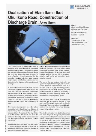
  • 1. Dualisation of Ekim Itam - Ikot Oku Ikono Road, Construction of Discharge Drain, Akwa Ibom Client: Akwa Ibom State Ministry of Works and Transport Construction Period: 01/2009 – 12/2011 Services: Construction of 3km drainage system, inner diameter 2,000mm Uyo, the capital city of Akwa Ibom State, is located on a flat area (plateau) without natural surface drainage, where the rainfall of 3,000mm per year cannot be discharged properly. During the long rainy season the area is subject to severe flooding. As a consequence, the city was often inundated with storm water causing major impacts to traffic flow, business and are the potential for damage to infrastructure and buildings. In combination with the construction of three new flyover bridges and the dualisation of the Ekim Itam – Ikot Oku Ikono Road, a solution for the discharging of the surface water of roads, flyovers and the adjacent areas was required. Julius Berger Nigeria PLC received in 2009 the contract for the construction of a rainwater and surface drainage system for the township of Uyo. The nearest discharge point is a valley with a connection to the Ikpa River in a distance of approximately 3km northeast of the flyover location at Itam Roundabout. The city of Uyo is located approx. 70m above sea level; the bottom of the valley is 25m above sea level. For these preconditions a technical solution was found. To discharge the surface water, the construction of an underground drainage pipeline with a total length of 2,300m and an inner diameter of 2,000mm was finally designed. Due to the existing geology and topography the pipeline is built as a micro tunnelling system through the so called ‘pipe jacking’ method, a closed construction of concrete pipes and a stilling basin at the end. With this system, massive earth works and demolition works could be avoided. The entire drainage system starts with an open U-channel of 400m length with the cross section 1.5x2.0m. The U-channel ends in a manhole which is equally the starting point of the underground discharge pipeline. The total pipeline distance of 2,300m is divided by 4 manholes, which are called the start- & target manholes for the ‘pipe jacking’ system. The manholes were built as an overlapped bored pile wall with an inner diameter of 11m (start) and 7m (target) respectively and up to 23m depth. These manholes were additionally used as inlet points for the surface drainage system of the adjacent areas. The pipeline is located in a depth between 6m and 45m. The pipes have joining with rubber sealing and are waterproof from inside and from outside. The longitudinal slope of the pipeline is up to 4.2% in the last section. At the end of the pipeline a stilling basin is constructed to reduce the velocity of the water. The maximum discharge capacity of the pipeline is 21m³ per second, while the expected flow velocity is 7-8m per second. JBNProjectBookNo.NG-2007-041-02