

Recomendados
Recomendados
Mais conteúdo relacionado
Mais procurados
Mais procurados (20)
Semelhante a Iskra MC 760 Network Analyzer - Datasheet Manual
Semelhante a Iskra MC 760 Network Analyzer - Datasheet Manual (20)
Mais de Angus Sankaran
Mais de Angus Sankaran (20)
Último
Último (20)
Iskra MC 760 Network Analyzer - Datasheet Manual
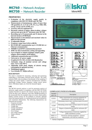
- 1. Page 1 MC760 − Network Analyser MC750 − Network Recorder PROPERTIES • Evaluation of the electricity supply quality in compliance with SIST EN 50160 (only MC760) • Measurements of instantaneous values of more than 140 quantities (U, I, P, Q, S, PF, PA, f, φ, THD, MD, energy, energy cost by tariffs, etc.) • Accuracy class 0.5 (optional 0.2) • Harmonic analysis of phase, phase-to-phase voltages and currents up to the 63rd harmonic (only MC760) • Recording up to 32 measurands and 32 alarms in the internal memory (8 MB flash) • Measurements of 40 minimal and maximal values in different time periods • 32 adjustable alarms • Frequency range from 16 Hz to 400 Hz • RS 232/RS 485 communication up to 115,200 bit/s or Ethernet communication • MODBUS and DNP3 communication protocol • MMC for data transmission, setting and upgrading • Up to 4 inputs or outputs (analogue outputs, pulse outputs, alarm outputs, tariff inputs) • Additional communication port (COM2) • Universal or AC power supply • Graphical LCD; 128 x 64 dots with illumination • Automatic range of nominal current and voltage (max. 12.5 A and 750 V) • Adjustable tariff clock, display of electric energy consumption in optional currency • Multilingual support • User-friendly PC MiQen software DESCRIPTION The meter is intended for measuring, analysing and monitoring single-phase or three-phase electrical power network. The meter measures RMS value according to the principle of fast sampling of voltage and current signals. A built-in microprocessor calculates measurands (voltage, current, frequency, energy, power, power factor, THD phase angles, etc.) from the measured signals. USE The MC760 network analyser is used for permanent analysis of electricity supply quality in compliance with the SIST EN 50160 standard. Records are stored in the internal memory for the period of the last three years. Moreover, more than 100,000 deviations of the measurands from the standard values are stored, which enables finding eventual reasons for the problems in network. Optional limits and required quality in a monitored period can be defined for each monitored characteristic. The following characteristics are measured and recorded: • Frequency deviations • Voltage deviations • Voltage dips • Voltage interruptions • Voltage unbalances • Over-voltages • Fast voltage changes • Flicker intensity • THD • Harmonics COMPLIANCE WITH STANDARDS: Standard SIST EN Description 61010-1 Safety requirements for electrical equipment for measurement, control and laboratory use 61036* Alternating current static watt-hour meters for active energy 61268* Alternating current static var-hour meters for reactive energy 60529 Degrees of protection provided by enclosures (IP code) 50160 Voltage characteristics of electricity supplied by public distribution systems 62052−11 62052−21 Electricity metering equipment – General requirements, tests and test conditions * − Partial compliance
- 2. DESCRIPTION OF PROPERTIES MEASURANDS • RMS values of currents and voltages • Measurements of energy, power and power factors in all 4 quadrants • Minimal / maximal values • Average values of measurands per interval • Measurement of THD values of current and voltage (from 0 to 400 %) • Harmonic analysis of phase, phase-to-phase voltages and currents up to the 63rd harmonic RECORDER A built-in recorder (8Mb) enables storing measurements and detected alarms. The recorder is additionally used for measurements related to the inspection of voltage quality. ALARMS The meter supports recording and storing of 32 alarms in four groups. A time constant of maximal values in a thermal mode, a delay time and switch-off hysteresis are defined for each group of alarms. COMMUNICATION The meter is equipped with RS232 and RS485 communication via the DB9 terminal or Ethernet communication via the RJ-45 terminal. Communication enables transfer of instantaneous measurements, records in the memory, settings and updating. Communication supports MODBUS and DNP3 protocols. MMC The meter is provided with a slot for a full size MMC (128Mb to 512Mb). It is used for transfer of measurements from the internal memory, the meter setting and software updating. INPUT / OUTPUT MODULES The modules are available with double inputs/outputs. Each module has three terminals. The meter is available without, with one or with two modules. The following modules are available: • Alarm output 2 outputs • Analogue output 2 x 20 mA outputs • Pulse output 2 outputs • Tariff input 2 inputs • Bistable alarm output 1 output • Additional communication port (COM2) SUPPLY Power supply connection of the meters (MC) is adaptive. A universal power supply enables connection of the meter to DC (20−300 V) or AC voltage (48−230 V / 50 Hz). AC power supply enables connection of the meter to AC voltage (57.7 / 63.5 / 100 / 110 / 230 / 400 / 500 V). HANDLING THE COSTS A special meter function is cost evaluation of energy (active, reactive and total) per tariffs. The meter itself enables tracing the costs in optional currency and calculates consumption by means of the adjustable tariff clock and electric energy price. MIQEN MiQen software is intended for supervision of the meter on PC. Network and the meter setting, display of measured and stored values and analysis of stored data in the meter are possible via the serial or Ethernet communication. The information and stored measurements can be exported in standard Windows formats. Multilingual software functions on Windows 98, 2000, NT, XP operating systems. DATA DISPLAY Data are displayed on 128 x 64 dot graphic LCD with illumination (37 x 69 mm). Indication symbols on the front side that are illuminated at the access to MMC, communication and alarm are of additional help. TECHNICAL DATA EU DIRECTIVES: Decree on electrical equipment designed for use within certain voltage limits URLRS 53/00 (Directive 73/23/EEC on low voltage): SIST EN 61010-1: 2002 Safety requirements for electrical equipment for measurement, control and laboratory use, part 1: General requirements Decree on electromagnetic compatibility (EMC) URLRS 61/00 (Directive 89/336/EEC on electromagnetic compatibility): SIST EN 61036 item 4.5: 1998 Meters for active energy (classes 1and 2). SAFETY: • Protection: protection class II 600 V rms, installation category II 300 V rms, installation category III pollution degree 2 in compliance with SIST EN 61010-1: 2002 • Enclosure material: PC/ABS incombustibility–self-extinguishability, complying with UL 94 V-0 • Enclosure protection: IP 52 (IP 00 for terminals) in compliance with SIST EN 60529: 1997 • Cutting for installation: 92+0,8 mm • Converter mass: approx. 600 g AMBIENT CONDITIONS: • Climatic class: 3 in compliance with SIST EN 62052−11: 2004 in compliance with SIST EN 62052−21: 2005 • Temperature range of operation: -10 to +65°C • Storage temperature range: -40 to +70°C • Average annual humidity: ≤ 75% r.h. INPUTS Input signals Current Voltage Nominal frequency range 50, 60 Hz Measuring frequency range 16−400 Hz Nominal value (In, Un) 5 A 500 V L-N Maximal vale 12.5 A 750 V L-N Consumption < 0.1 VA < 0.1 VA POWER SUPPLY Power supply Universal AC Nominal voltage AC 48−230 V 57.7 / 63.5 / 100 / 110 / 230 / 400 / 500 V Nominal frequency 40−65 Hz 40−65 Hz Nominal voltage DC 20−300 V − Consumption < 5 VA < 7 VA AUXILIARY BATTERY A built-in auxiliary battery enables the clock operation and recording the measurements in the memory with the time flag. The battery shall be replaced by the authorised service. • Type CR2032 Li-battery • Nominal voltage 3 V • Life span approx. 6 years (typical 23°C) REFERENCE CONDITIONS • Ambient temperature: −10, 22 and 55°C • Input: 0…100 % Un • (connected to a measuring transformer) 0…100 % In • Active/reactive power, factor: cosϕ =1 / sinϕ =1 • Sine form: Sinus ACCURACY Accuracy is presented as percentage from nominal value of the measurand except when it is stated as an absolute value. Page 2
- 3. Page 3 Measurand Accuracy Rms current (I1, I2, I3, Iavg, In) 0.5 (optional 0.2) Rms phase voltage (U1, U2, U3, Uavg) 62.5−750 V 10−500 V <0.5 (optional 0.2) 0.5 (optional 0.2) Phase-to-phase voltage (U12, U23, U31, Uavg) 0.5 Frequency (f) 10 mHz Power factor (PF) 0.5 Phase and phase-to-phase angle (φ, φ12, φ23, φ31) 0.5 THD 0…400 % 0.5 Measurand Accuracy Active, reactive and apparent power 0.5 (optional 0.2) Active energy SIST EN 61036 Class 1 Reactive energy SIST EN 61268 Class 2 REAL TIME CLOCK (RTC): RTC accuracy 1 min/month (30 ppm) CONNECTION Converter voltage inputs can be connected either directly to low-voltage network or via a high-voltage transformer to high- voltage network. Current inputs shall be connected to network via a corresponding current transformer. U V U V 9 6 5 1 11 2 5 8 13 14 L1 N K k j J CT2 CT3CT1 15 16 17 18 19 20 1b − single wire, uniform load U V U V U V U V 9 6 5 1 11 2 5 8 13 14 L1 L2 L3 K k j J CT2 CT3CT1 9 6 5 1 11 2 5 8 13 14 L1 N K k j J CT2 CT3CT1 U V U V 15 16 17 18 19 20 L2 L3 15 16 17 18 19 20 3u − three-wire, uniform load 4b − four-wire, uniform load U V U V U V U V 9 6 5 1 11 2 5 8 13 14 L1 L2 L3 K J k j kJ K CT2 CT3CT1 j 15 16 17 18 19 20 U U U U U U V VV V VV N N 11 2 5 8 13 14 K J k j jk k K J K CT2 CT3CT1 j J L1 L2 L3 N 15 16 17 3b − three-wire, uniform load 4u − four-wire, non-uniform load DIMENSIONAL DRAWINGInputs / Quantities Terminals Measuring inputs: AC current IL1 TT1 IL2 TT2 IL3 TT3 AC voltage UL1 2 UL2 5 UL3 8 N 11 Auxiliary power supply: + / AC 13 – / AC 14 Inpt / Output modules Module 1 I/O−1 15 C−12 16 I/O−2 17 Module 2 I/O−3 18 C−34 19 I/O−4 21 TERMINALS TYPE OF COMMUNICATION Communication Terminals DB9 female RS 232 Rx 3 # 5 Tx 2 RS 485 B 7 A 8 RJ-45 Ethernet TD+ 1 TD− 2 RD+ 3 RD− 6 Screw terminals (COM2) RS 232 Rx 18 # 19 Tx 20 RS 485 B 20 A 18 Connection Max. conductor cross-sections Voltage inputs (4) ≤ 5 mm2 ; one conductor Current inputs (3) ≤ Ø 6 mm; one conductor with insulation Power supply (2) ≤ 2.5 mm2; one conductor Modules (2 x 3) ≤ 2.5 mm2; one conductor COMMUNICATION CONNECTION Ethernet RS 232 RS 485 Type of connection Direct Network Max. connection length - 3 m 1000 m Terminals RJ-45 DB9 female Insulation 3.7 kV rms., 1 minute between terminals and other circuits Transfer mode Asynchronous Protocol MODBUS RTU / DNP3 Transfer rate 10/100Mb/s autodetect 1.200 do 115.200 bit/s
- 4. DATA FOR ORDERING Measuring centre: The following data shall be stated: • Type of a meter Printed in Slovenia • Subject to change without notice • Version 03 / nov. 2009 • E P22.440.000 • Type of power supply • Type of communication • Type of a module(s) • MMC (option) Supplement: • MiQen software ORDERING When ordering the meter, all required specifications shall be stated in compliance with the ordering code. The meters automatic range of input current (up t 5 A) and voltage (up to 500 VL-N) is not stated in the code. EXAMPLE OF ORDERING: The MC760 network analyser is connected to secondary phase voltage up to 500 VL-N and 5 A secondary current. A universal supply is built-in the meter. RS 232/RS 485 communication and two modules are applied The first module is an alarm output and the second one is a pulse output. A memory card with 1GB capacity is also ordered. Ordering code: MC760−EDC/AC−RS−2AL 2PO−1G Dictionary: RMS Root Mean Square Flash Type of a memory module that keep its content in case of power supply failure Ethernet IEEE 802.3 data layer protocol MODBUS / DNP3 Industrial protocol for data transmission MMC MultiMedia Card MiQen Software for MC meters AC Alternating current PA Power angle (angle between current and voltage) PF Power factor THD Total harmonic distortion MD Measurement of average values in time interval Harmonic voltage – harmonic Sine voltage with frequency equal to integer multiple of basic frequency Hand-over place Connection spot of consumer installation in public network Flicker Voltage fluctuation causes changes of luminous intensity of lamps, which causes the so-called flicker RTC Real Time Clock GENERAL ORDERING CODE All specifications are obligatory except MMC. An example of a completely filled-in ordering code: MC760−EDC/AC−RS−2AL 2PO−1G Meter type MC760 MC750 Power supply EDC/AC Universal E57,7V 57.7 V AC E63,5V 63.5 V AC E100V 100 V AC E110V 110 V AC E230V 230 V AC E400V 400 V AC E500V 500 V AC Communication (COM1) RS RS 232 / RS 485 E Ethernet Module 1 / Module 2 WO Without 2AL 2 X Alarm output 2AN 2 X Analogue output 2PO 2 X Pulse output 2TI 2 X Tariff input 1BAL 1 X Bistable alarm output 2DI 2 X Digital input RS2 1 X RS 232 (COM2) – only module 2 RS4 1 X RS 485 (COM2) – only module 2 MMC (option) 1GB