
Recomendados
Recomendados
Mais conteúdo relacionado
Mais procurados
Mais procurados (19)
Semelhante a Report on Madras Atomic Power Station Emass Coolant Channel Replacement
Semelhante a Report on Madras Atomic Power Station Emass Coolant Channel Replacement (20)
Report on Madras Atomic Power Station Emass Coolant Channel Replacement
- 1. Asian Nuclear Prospects 2010 En-Masse Coolant Channel Replacement in Indian PHWR Joy P. Varghese, V.S. Verma, C.D. Rajput, K. Ramamurthy Abstract This paper describes in brief the need for the coolant channel replacement, the challenges faced, the methodology adopted to successfully overcome the shortcomings, and the improvements made in various areas that set a new standard in the global nuclear industry.These changes have streamlined the en-masse coolant channel replacement programme which was followed during the subsequent campaigns. © 2010 Published by Elsevier Ltd Keywords: coolant channel; PHWR; MAPS; fuel bundle; pressure tubes 1. Introduction Madras Atomic Power Station (MAPS) houses two pressurized heavy water reactors, each rated for 230MWe. Indigenization of the country’s nuclear power programme was launched with the successful construction and commissioning of these two reactors. Entire responsibility for the execution of this project including design, engineering, erection, commissioning and operation was shouldered by Indian engineers and scientists. These reactors use natural uranium as fuel and heavy water as moderator and primary coolant. These reactors have 306 horizontal coolant channel assemblies each of which house 12 fuel bundles with shielding plugs and sealing plugs at either ends.Pressure tubes and calandria tubes of these reactors are made off Zircaloy-2. With the hydriding phenomenon in pressure tubes, coolant channel assembly, which is designed to be replaced, becomes one of the life limiting components of the reactor. Rajasthan Atomic Power Station-2 (RAPS-2), which was constructed under Indo-Canadian collaboration, was the first Indian reactor to undergo En-masse Coolant Channel Replacement (EMCCR) programme. The EMCCR campaign was executed by Indian engineers, which demonstrated technological expertise and self reliance to carry out such major core component replacement work. ______________ *Correspondingauthor.Tel.: +91-44-27480320; fax: +91-44-27485134 E-mail address: jvarghese@npcil.co.in
- 2. Joy P. Varghese et al. / Energy Procedia 00 (2010) 000-000 MAPS-2 was the next reactor to undergo the EMCCR. MAPS-2 had then completed 8.5 full power years of operation. Extension of operation called for large scale inspection, which necessitated long shut down. In keeping with the safety considerations, it was decided to replace the coolant channel assemblies. Accordingly, MAPS-2 was shut down on 9th January 2002 for EMCCR. Experience gained at RAPS-2 was effectively utilized in modifying the tooling and procedures. The main focus of the MAPS-2 campaign was to reduce the down time, manrem, improved safety performance and quality assurance. A small step was taken towards automation during this campaign. The changes introduced resulted in the campaign being completed in record time, setting a new benchmark in the nuclear industry. MAPS-1 had completed 10.1 Full Power Years of operation after which it was shut down for EMCCR on 20th August 2003. For the MAPS-1 EMCCR, several steps were taken to introduce semi- automatic mode of operation for manrem intensive activities. Increased mechanization in the areas of working platforms, material handling systems, radioactive material handling and reinstallation of precision components were the main features during the MAPS-1 campaign. 2. Need for en-masse coolant channel replacement Pressure Tubes are supported on end shields by the end fittings. Two loose fitting garter springs over each pressure tube ensure gap between pressure tubes (PT) and calandria tubes (CT). Pressure tubes operate in the environment of high neutron flux, high temperature and high pressure. With extended operation under fast neutron influence and due to corrosion, deuterium level increases in Zircaloy-2 pressure tubes. This increase in deuterium level makes the pressure tube more susceptible to delayed hydrogen cracking. Important phenomenon which limit the life of pressure tube are dimensional changes due to creep, hydrogen pick up, thermal gradient caused at the point of contact between pressure tube and calandria tube which could result in blisters. This implies that the pressure tubes would demand replacement at certain points of power operation. 3. Major design changes During EMCCR, some major changes were brought in with regard to the material of pressure tubes, the hardware and the rolled joint geometry to improve the performance and to enhance the life of coolant channels. Some of the major design changes were: Zr-2.5% Nb in place of Zr-2 material for pressure tubes. The new material has superior characteristics such as low hydrogen pick up, low creep rate and high strength. The higher strength of the material paved way for reduced wall thickness of PT with consequent neutron economy and low initial hydrogen. 4 Nos. of tight fit garter springs instead of the two loose fit garter springs. Zero clearance shop joint and low clearance field joint instead of the clearance joints with Zr- 2 to ensure low residual stress on rolled joints. Modified journal rings to accommodate higher creep allowance of 126 mm as against the earlier limit of 63 mm. 4. Phases of EMCCR campaign After the completion of de-contamination and defuelling of the reactor core the EMCCR activities are divided in to various phases, which are further subdivided in to modules to have effective control. The various phases are: Preparatory Phase: Infrastructure requirements for the campaign like track and trolley system from service building to respective vaults, erection of vault cranes, erection of platforms, working trolleys and control room with audio and video facilities were established. Removal Phase: This phase mainly consists of removal of jig-saw panels, separation of feeders, pressure tube cutting, ATC removal, end fitting removal, pressure tube removal and disposal. Inspection Phase: Inspection activities such as calandria tube inspection, feeder thickness measurement, sag measurement, etc are completed during this phase.
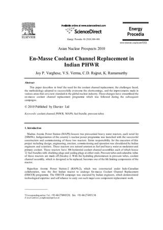
- 3. Joy P. Varghese et al. / Energy Procedia 00 (2010) 000-000 Reinstallation Phase: Shop rolling of the pressure tube, installation of garter springs, in-situ rolling along with installation of the ATC hardware and feeder connections are the key activities during this phase. Re-commissioning Phase: Coolant channels are loaded with new fuel, hydro test of the PHT system is carried out and the jig-saw panels are installed back. The Unit is brought back to service by the end of this phase. 5. Challenges and improvements 5.1. FM vault cranes Unlike in RAPS, the FM vaults did not have crane facility at MAPS. Crane, with similar specifications as the RAPS cranes, was procured for MAPS-2 and many difficulties were faced during the operation and maintenance of these cranes. The crab was complicated with two separate hoists of 5+5 tons and one auxiliary hoist of 1 ton. One of the major difficulties was the handling of the PT flask on evener beam with the 5+5 ton hooks. Though gang operation was provided for both hooks, due to differing breaking friction, hook elevations was changing often. Considering this difficulty, MAPS-1 Cranes have been modified. The hoist was changed to have single hook of 10 ton capacity. Hoist motor was modified to VVVF design. Radio remote for easy operation of the crane was incorporated. Cross travel and long travel motors and gearboxes were made identical for inter changeability. Complete crane assembly, including the long travel rail and the limit switches, was mock erected at CCR shop and performance checked. 5.2. Track and trolley mechanism For shifting of heavy materials like platform structures and flasks, a simple arrangement of rail and trolley with manual pushing was used at RAPS-2. At MAPS-2, self elevating platform was a heavy structure which necessitated power operation for these trolleys. Winches were also used for rail trolley systems from the service building to the FM bay and fromthere on to the respective vault. For MAPS-1 campaign, low bed trolleys with anti-derailment guards were used. The drum was modified to take the trolley from SB to FM bay and back by just reversing the drive. A similar system was used for trolley from FM bay to FM vaults. 5.3. Platforms Working platforms, with flexibility for approach to the width of reactor face as well as facility to raise and lower for approaching various rows, are needed for carrying out activities in both the FM vaults. At RAPS-2 simple structural platforms were used, which could be raised and lowered by operating four manual chain pulley blocks. The complete platform had to be moved from column to column in the east west direction for complete reach. This platform offered minimal shielding. For MAPS-2, a heavily shielded 75 ton self elevating platform driven by 3 ball screws was used in one of the vaults where the major activities were carried out (Fig. 1). A full width platform made of structural members weighing about 10 tons with light shielding in the front was used in the other vault. Both these platforms performed with out any major breakdowns and manrem expenditure for assembly and dis-assembly of both the platforms was comparable.
- 4. Joy P. Varghese et al. / Energy Procedia 00 (2010) 000-000 Fig.1. Remotely operable shielded platformbeing used during EMCCR For MAPS-1, self elevating platforms were used in both the vaults, resulting in considerable manrem reduction. 5.4. Working trolleys: Working trolleys are required for precise positioning of various equipment such as end fitting flask, PT flask, PT-EF assembly etc. These trolleys shall have flexibility in the X & Y direction for precise alignment with the lattice bore. In the RAPS-2 & MAPS-2 campaign an alignment saddle was used and alignment was carried out manually by rotating the hand wheel in the direction desired. For the MAPS- 1 campaign a remotely operable trolley, with an electrical drive in X-direction and hydraulic jack in Y- direction was designed. These trolleys were operated from the control centre with provision for local operation in exigencies. Position indications for the trolley were available fromglass switches mounted on the floor. 5.5. Shield plug pushing and temporary shield plug installation Coolant channel shield plugs are disposed along with pressure tubes. For this purpose the fuellin g machines deposits the plugs just beyond grooves during the final draining operation. During the removal stage the pressure tubes are to be cut just beyond the rolled joint. For approaching this area as well as for installing puller and pusher tools the shield plugs are to be pushed 2500 mm from the E- face. During the RAPS-2 Campaign an aluminium pusher tool was used to push the shield plugs manually. During MAPS-2 campaign carbon steel tools were used with good result. Hydraulic cylinder of 3 meters stroke length, mounted on remotely operable trolley, was used in MAPS-1 campaign with considerable saving in manrem. After the end fittings are removed, two temporary shield plugs, each weighing 15 kg, are installed to avoid beaming radiation from the lattice bore. These plugs were installed with a long tool of 2m length, having thread engagement at the tip, which posed difficulties due to the weight and large over hang. During the MAPS-1 Campaign, an electro-magnet attached to a hydraulic cylinder and mounted on remotely operable trolley, was used for handling these plugs.
- 5. Joy P. Varghese et al. / Energy Procedia 00 (2010) 000-000 5.6. Pressure tube cutting tool Pressure tube is to be cut just beyond the end fitting rolled joint area. For this, a long tool capable of making the cut about 2.1 metres inside the coolant channel assembly and driven by air motor, was designed. In the initial design this tool was freely supported in the end fitting, leading to increased friction during cutting operation. In the MAPS-2 Campaign the tool was provided with deep groove ball bearing, clamped to the E-face, to support the tool. With this change, the cutter life increased from a maximum of 2 cuts to a minimum of 10 cuts. To further reduce friction, the head was modified to incorporate needle roller bearing without inner race. This change facilitated supporting of the tool at the front end as well, further improving the performance. 5.7. ATC removal The AT hardware holds the coolant channel assembly in position while permitting axial movement and preventing transfer of a torque to the rolled joint. Nickel sleeve absorbs energy due to momentum in accident condition or pressure tube failure. This assembly is to be removed to remove the end fitting and is replaced with a new design. During RAPS-2 campaign, the traditional method of removal of lock nut and main nut along with nickel sleeve thrust collar was done with a simple hexagonal socket with extensions. Threads on the ATC studs are of fine nature requiring a number of rotations to remove main nut and lock nut and possibility of galling is high due to material properties. After removal of end fitting the studs were removed for installation of the new assembly. In RAPS-2 several of these studs broke at the neck and were to be drilled and removed. Re-tapping of the tube sheet was to be done later, which was a cumbersome operation demanding working very close to end shield tube sheet. During the MAPS-2 campaign, controlled application of torque was stipulated in procedure to avoid stud breakage. Stud along with lock nut and main nut was removed in one shot to avoid repeat visit, to save manrem. This procedure too posed difficulty in about 25% of the channels due to galling of ATC main nuts,lock nuts and the studs.Ingenious methods like nut splitting and grinding were used to remove the complete ATC hardware. For MAPS-1 campaign a fixture, taking guide from two adjacent end fittings was used to locate the tool for removal of the ATC. The grinding fixture was modified with spring loaded feed mechanism such that once the fixture is set up, manual intervention is not required during the 30 minutes of grinding operation. 5.8. End fitting removal The traditional method of removal of end fitting, with the help of the balancing tool, was adopted at RAPS-2 and MAPS-2. The end-fitting flask was lifted to top of the platform and placed at an angle of 45° close to the lattice location with the cold end of the flask left open. End fitting balancing tool was inserted in to the end fitting and manually clamped. The end fitting was pulled out by moving the crane and was inserted in to the flask. During this operation, the hot end of the end fitting is exposed in the vault and the background rises significantly. During the total operation of removal, a minimumof three persons are required to be present in the vault platform (Fig. 2).
- 6. Joy P. Varghese et al. / Energy Procedia 00 (2010) 000-000 Fig. 2. End fitting removal operation The scheme was modified such that end fitting is drawn out directly into the end fitting flask by having the end fitting flask on a remotely operable trolley along with coarse positioning facility in X- direction. End fitting handling tool was fitted with a pneumatically operated jaw mechanism and a winch for pulling and pushing. A remotely operable camera system with instrumentation provides the necessary feedback during operation. All these modifications resulted in considerable saving in manrem. 5.9. Pressure tube removal PT removal is carried out with the help of the puller tool and pusher tool held as a train. During PT removal, garter springs are to be collected separately in the garter spring flask. During the RAPS-2 campaign the complete operation was done on the structural platforms, which hardly offered any shielding. Pushing and pulling operation were carried out and PT was received in to the PT flask while the garter springs were collected in the garter spring flask.
- 7. Joy P. Varghese et al. / Energy Procedia 00 (2010) 000-000 Fig. 3. Handling and transportation of shielding flask In MAPS-2, self-elevating platform was used on one side, where the PT and GS were collected. Pushing was done from one vault while pulling was done with the help of winch operator sitting on the floor. For MAPS-1, only pulling operation was performed with the help of torque control pneumatic winch. No pushing operation was involved, eliminating the occupancy in the other vault. The pusher tool was kept connected to the power arm, which moved along with the pressure tube. GS flasks were provided with pneumatically operated lid mechanism with a feature to leave the lid open in case of air failure. A system of four cameras, which were remotely operated, identified the inventory of garter springs. Fig. 3. shows the PT flask in position to receive the tube. Subsequently it is transferred to the storage pool for long storage (Fig. 4.)
- 8. Joy P. Varghese et al / Energy Procedia 00 (2010) 000-000 Fig. 4. Transferring of pressuretube For cleaning of calandria tubes in MAPS-1, a remotely operated power arm was designed to take cleaning bung for the full length of calandria tube. 5.10. Integrated PT-EF and GS installation system Pressure tube is connected with the end fittings by rolled joints. Fig. 5. shows the pressure tube being trimmed to the required length. One joint is made outside the reactor and is called the Zero clearance shop joint while the other is carried out in the reactor and is called the low clearance in-situ joint. PT- EF assembly is inserted in the calandria and locked from one end and the garter springs are installed one by one from the other vault. After installation of garter springs the other end-fitting assembly is installed and final rolling is carried out. Fig. 5. Pressure tubepositioning for trimming
- 9. Joy P. Varghese et al. / Energy Procedia 00 (2010) 000-000 After removal of the temporary shielding plugs, PT-EF assembly is aligned with the desired lattice location, which required about four persons on the vault platform. After the installation of PT-EF assembly is completed the garter springs are installed by a crew of 4 persons. At first the guide tool made of aluminium is inserted in to the pressure tube and the first garter spring is rolled over this guide tube. With a short insertion sleeve, the garter spring is pushed onto the pressure tube. After removal of the short sleeve GS-1 installation sleeve is inserted till the stoppertouches the end shield tube sheet and GS-1 sleeve is with drawn. Similar procedure is repeated for GS-2, GS-3 & GS-4 installation. The procedure was quite cumbersome with possibility for committing errors. While pushing the GS on to pressure tube, if the guide tool is not held firmly, it may slip on to the nosepiece after which it could drop in the annular space. Garter spring installation takes about 20 minutes and hence on line eddy current testing to assess the position of garter spring is not feasible. PT-EF installation and garter spring installation were two independent activities, which necessitated repeat operation with multiple crews. In MAPS-1, a modified scheme was followed wherein a tubular fixture was devised to hold four garter springs like a cartridge. The assembly is taken to the south vault and installed in position independently. Subsequently the north side is opened and the garter spring is installed in required position, which is done along with the eddy current testing to confirmthe same. With this method, PT- EF insertion and garter spring installation are completed in one sequence, thus reducing manrem and the time required for completion of work. 5.11. Reinstallation and normalization of coolant channels: In RAPS-2 & MAPS-2, EMCCR activities were carried out as a batch processing to utilize the skills of the personnel involved and to focus on specific procedures. The disadvantage of the systemwas the difficulties in approaching ATC hardware after all the end fittings are installed. In MAPS-1 campaign the operation was carried out row wise, which resulted in ease of installation of the ATC hardware and gray loc joints. 6. Conclusion The EMCCR, a unique and highly dose intensive campaign involving large man power, was carried out for the first time in any Indian pressurized heavy water reactor in RAPS-2 (1996-97) by indigenously developed tools and expertise. With the experience and expertise gained from the RAPS campaign, the EMCCR was carried out in MAPS-2 and subsequently in MAPS-1 which was also unique in several respects - in terms of expertise, tools development, man power deployment, job execution, generation of data base and, above all, in completing the whole campaign in record time well ahead of schedule from the day of shutting down of the reactor. The whole campaign was split into several task wise modules for easy and effective execution and was carried out round the clock. The quality assurance plan during the campaign was of high standards which ensured that the workmanship was of established standards. The biggest challenge of the campaign was the management of the personnel radiation exposure. The chemical decontamination of the system ensured that the systemwas devoid of the radioactive contamination and thus brought down the radiation levels at locations of work. In view of the high intensity, non- uniform radiation field fromthe channels, control of external exposures to the working personnel was the main focus during the campaign. Mock up facilities were established, and personnel were trained and qualified to work in high radiation environs. The heavily shielded platform further reduced the radiation levels on the working platforms to comfortable levels. By adopting these efficient and time saving technologies the duration of work was also reduced, thus saving on manrem, and the campaign has set benchmarks in the industry.