Mais conteúdo relacionado
Semelhante a Pic bluetooth (20)
Pic bluetooth
- 1. FlexiPanel
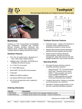
ToothpickTM
PIC with integral Bluetooth and Toothpick Services firmware layer
phone and module not to scale
Summary
Toothpick is a PIC microcontroller and BlueMatik
radio combination, preloaded with Toothpick
Services firmware providing FlexiPanel user
interface server, wireless field programming and
Toothpick Slave for optional external host control.
Hardware Features
• FCC / CE / IC certified Class 1 Bluetooth V1.1
radio, 100m range, integral antenna
• 128Kbyte Flash, 3.5K RAM, 1K EPROM up to
512Kbyte I2C external memory
• 12 × 10-bit A to D converter
• 5 × 10-bit PWM outputs
• Serial UART, I2C and SPI communications
• 2 interrupts
• 20MHz and 32KHz oscillators
• Low dropout 400mA power regulator
• 45 x 22 mm through-hole mount, suitable for
breadboards
AN0 - AN11
TxD - RxD
CCP1 - CCP5
SDA - SDO - SCL
INT0 - INT1
20MHz 32768Hz
PIC18LF6720
Vdd
Green Red Pushbutton
Vin
LDO 5V reg
400mA
Bluematik
Bluetooth
module
Toothpick Services Features
• FlexiPanel server – creates user interfaces on
computers, PDAs, cellphones with no
development needed on remote devices
• Wireless field programming lets developers
distribute firmware upgrades electronically
• System services including: Bluetooth
communications, interrupt and memory
management, sleep-safe real time clock with
daylight savings time / day-of-week calculator
Operating Modes
• Pre-tested Firmware Solutions ready for
immediate standalone operation:
- HappyTerminalTM TTL Terminal Emulator
- OpenToothTM Bluetooth device sensor
- DARC-ITM Data acquisition and remote
control managed via Bluetooth
- DARC-IITM Data acquisition and remote
control with FlexiPanel User Interface
• Toothpick Slave where Toothpick is controlled
by a host processor via a serial link.
• Standalone Toothpick programmable in C for
low-cost, customized standalone operation.
Ordering Information
Part No Description
TOOTHPICK Toothpick 28-pin Dual-in-Line package evaluation version
TOOTHPICK-xxx Toothpick 28-pin Dual-in-Line package – Custom firmware xxx
Manufactured to ISO9001:2000
Page 1 2-May-06 Toothpick 3.0.00009 DS380-8 © FlexiPanel Ltd Patents apply and/or pending www.FlexiPanel.com
- 2. Toothpick
Summary ........................................................................................................1
Mechanical Data ............................................................................................3
Pin Descriptions ............................................................................................4
Technical Specifications...............................................................................5
Schematic Diagram .......................................................................................6
Overview.........................................................................................................7
Hardware Design ...........................................................................................8
Application Development Guide ................................................................10
Programming ToothPIC ..............................................................................12
Hello World Bitstream Firmware Solution ................................................16
Hello World FlexiPanel Firmware Solution ...............................................20
BlueMatik Diagnostic Firmware Solution..................................................26
ToothPIC Diagnostic Firmware Solution...................................................28
DARC-I Firmware Solution..........................................................................34
DARC-II Firmware Solution.........................................................................37
HappyTerminal Firmware Solution ............................................................42
OpenTooth Firmware Solution...................................................................45
ToothPIC Slave Firmware Solution............................................................48
Guide to ToothPIC Slave Development.....................................................55
Guide To MPLAB C18 Development..........................................................76
Designing User Interfaces ..........................................................................78
ToothPIC Services Reference ....................................................................80
Development Kit Inventory .......................................................................121
Revision History ........................................................................................122
Glossary and Notation ..............................................................................123
Legal Notices .............................................................................................125
Contact Details ..........................................................................................126
Name Change Notice
Toothpick was previously marketed under the name ToothPIC.
Since across-the-board name changes including directory names,
etc, might introduce errors, references to the old name may
appear in this technical documentation and related files.
Page 2 2-May-06 Toothpick 3.0.00009 DS380-8 © FlexiPanel Ltd Patents apply and/or pending www.FlexiPanel.com
- 3. Mechanical Data
Avoid PCB tracks and components close to antenna.
Ideally, locate on the edge of the main board.
CCP5
RxD
CCP3
CCP2
CCP4
TxD
AN9
AN0
INT1/PGC
INT0/PGD
SCL
Vss
Vdd
NMCLR
AN11
AN10
AN5
AN3
AN4
SDA
SDO
AN6
AN8
AN7
AN2
CCP1
AN1
Vin
antenna
18LF6720
32kHz
20MHz
LED Pushbutton LED
width 19.65
row pitch 17.78 (0.7 inch)
pin pitch
2.54mm
(0.1 inch)
45
offset
1.27mm
Main board PCB pad layout
hole dia 1mm
2.54mm
1.75mm x 1.75mm
5.5 4 6
Side view
External
antenna
connector
Dimensions in mm unless otherwise stated
Notes: Ensure the area where the module is mounted has a solid ground plane. To remove the module from
an IC socket or breadboard, lever it out using a screwdriver against the pin headers at the sides. Levering
from either end may damage components.
Page 3 2-May-06 Toothpick 3.0.00009 DS380-8 © FlexiPanel Ltd Patents apply and/or pending www.FlexiPanel.com
- 4. Pin Descriptions
Pin Name Description
AN0 Analog input / digital I/O
AN1 Analog input / digital I/O
AN2 Analog input / analog negative voltage reference input / digital I/O
AN3 Analog input / analog positive voltage reference input / digital I/O
AN4 Analog input / digital I/O
AN5 Analog input / digital I/O
AN6 Analog input / digital I/O
AN7 Analog input / digital I/O
AN8 Analog input / digital I/O
AN9 Analog input / digital I/O
AN10 Analog input / digital I/O
AN11 Analog input / digital I/O
CCP1 Capture / compare / pulse width modulation I/O
CCP2 Capture / compare / pulse width modulation I/O
CCP3 Capture / compare / pulse width modulation I/O
CCP4 Capture / compare / pulse width modulation I/O
CCP5 Capture / compare / pulse width modulation I/O
INT0 Interrupt pin / programming pin / digital I/O
INT1 Interrupt pin / programming pin / digital I/O
NMCLR Reset input / programming pin (may be left unconnected)
RxD UART serial data input / digital I/O
SCL I2C clock / SPI clock / digital I/O
SDA I2C data / SPI data input / digital I/O
SDO SPI data output / digital I/O / counter input / open drain output
TxD UART serial data output / digital I/O
Vdd Regulated +5V power input / output (note 1,2)
Vin Unregulated power input 5 – 10V (note 1,2)
Vss Power ground reference
1. Either (i) regulated power should be provided on Vdd and Vin left unconnected or (ii) unregulated power should be provided on Vin
and Vdd may be used as a regulated power output.
2. If internal regulator is used, total current draw on all outputs (including Vdd if used as a power output) shall not exceed 130mA
Page 4 2-May-06 Toothpick 3.0.00009 DS380-8 © FlexiPanel Ltd Patents apply and/or pending www.FlexiPanel.com
- 5. Technical Specifications
Physical
Max operating temperature -20ºC to +75 ºC
Max storage temperature -30ºC to +85 ºC
Dimensions L × W × H 45mm × 20mm × 10mm excluding pins
Electrical
Supply Voltage (unregulated) 5V to 10V
Supply Voltage (regulated) 4.5V to 5.5V
Peak power requirement excluding draw on I/O pins 270mA
Typical current, sleep mode <10μA est
Typical current, unconnected slave mode 20mA
Typical current, unconnected master mode 120mA
Typical current, connected, not communicating 40mA
Typical current, during transmit 250mA
Typical current, during receive 80mA
Maximum current on any I/O pin 25mA
Maximum total current on all I/O pins 200mA
Max voltage on I/O pins -0.5V to +5.5V
Please consult the documentation for the PIC18LF6720 available from Microchip Technology
(www.microchip.com) for further technical characteristics of the I/O pins.
Radio
Max RF output power Class I = 100mW = +20dBm
RF frequency range 2402MHz to 2480MHz
RF channels 79
Frequency hopping 1600 Hz
Range 100m nominal
Communication latency, μP to μP via two BlueMatik
30ms to 50ms
radios
Maximum data rate 50-90 Kbaud depending on conditions
Pairing method Unit link key
Please consult the documentation for the BlueMatik available from FlexiPanel Ltd (www.FlexiPanel.com) for
further technical characteristics of the Bluetooth radio.
Bluetooth qualification & logos and trademarks
The radio has been pre-qualified and is listed in the Bluetooth Qualified Products as B00524. FlexiPanel Ltd
is registered as an Adopter Member with the Bluetooth SIG, Inc. OEMs wishing to re-brand FlexiPanel Ltd
Bluetooth products and use the Bluetooth Logos and trademarks must also register as Adopter Members.
Membership is free, refer to www.bluetooth.org for details.
FCC, CE and IC modular approval
The radio has ‘modular approval’ for USA, Canada and certain European countries, provided the existing
integral antenna is used. The CE mark on the module indicates that it does not require further R&TTE
certification. The exterior of the product should be marked as follows:
Contains Transmitter Module FCC ID: CWTUGPZ1
Contains Transmitter Module IC: 1788F-UGPZ1
Page 5 2-May-06 Toothpick 3.0.00009 DS380-8 © FlexiPanel Ltd Patents apply and/or pending www.FlexiPanel.com
- 6. Schematic Diagram
22pF 22pF 22pF 22pF
20MHz 32768Hz
OSC1 OSC2 RC1 RC0
12
AN0 - AN11 AN0 - AN11
PIC18LF6720
Vin
TxD RG1
RxD RG2
CCP1 RC2
CCP2 RE7
CCP3 RG0
CCP4 RG3
CCP5 RG4
SDA RC4
SCL RC3
INT0/PGD PGD
RB0
INT1/PGC PGC
RB1
RC5
T0CKI
NMCLR
LDO 5V reg
400mA
Vout Vin
Gnd
Vss
Vdd
100nF 1uF
Vss
BlueMatik
Surface Mount
Bluetooth
module
Vdd
TxD
Vss
Vdd
AVdd
Vss
AVss
RC7
RB4
10K
2 x
BSS138N
4k7 4k7
8k1
RE2 HUM
8k1
RC6 RxD
8k1
RE3 Reset
8k1
RD7 On/Off
8k1
RD6 CTS
RB2 RTS
RB5 MUM
RE5 RD4 RB3
Green Red
Vss
Vdd
4K7
Vdd
SDO
NMCLR
1K
1K
47K
1uF
The BlueMatik Bluetooth radio is also available separately from FlexiPanel Ltd. For detailed information,
consult the BlueMatik technical specification available from www.FlexiPanel.com.
Page 6 2-May-06 Toothpick 3.0.00009 DS380-8 © FlexiPanel Ltd Patents apply and/or pending www.FlexiPanel.com
- 7. Overview
) Prefer to learn by doing? Head straight to
the “Hello World” Firmware Solutions.
ToothPIC combines a PIC18LF6720
microcontroller and a BlueMatik Bluetooth radio,
and is preloaded with ToothPIC Services including
FlexiPanel user interface server, wireless field
programming and ToothPIC Slave host-controlled
operation.
Application Development
There are four ways to develop an application
using ToothPIC:
1. Use a pre-compiled Standalone Firmware
Solution such as:
- OpenToothTM Bluetooth device sensor
- Data acquisition and remote control with
bitstream interface
- Data acquisition and remote control with
FlexiPanel service
2. Use the ToothPIC Slave Firmware Solution to
allow ToothPIC to be controlled by a host
processor.
3. Applications can be developed in C using
MPLAB C18 from Microchip Inc. This allows
the developer to take advantage of the
ToothPIC Services provided by FlexiPanel Ltd.
4. Applications can be developed using any
suitable microcontroller development system
such as Hi-Tech or CCS, although the
ToothPIC Services will no longer be available.
Firmware Solutions, including the ToothPIC Slave,
are relatively straightforward and suitable for most
skill levels. In general, source code is provided for
Firmware Solutions so that developers may
inspect the programming techniques employed
and use them as starting-points for customized
solutions.
) Technical support for one-off, hobbyist and
student projects is limited to Firmware
Solutions and ToothPIC Slave.
Development using MPLAB C18 and/or other
development systems minimizes cost but is
relatively advanced and full proficiency with the
development system is a necessity.
The Bluetooth radio used in ToothPIC is the same
component as used in FlexiPanel Ltd’s BlueMatik
and LinkMatik Bluetooth serial bridge modules.
Wireless Field Programming
ToothPIC’s wireless field programmer allows both
developer code and ToothPIC Services to be
upgraded using any Bluetooth-equipped PC.
Developers can distribute products and then at a
later date provide firmware upgrades to customers
as required.
FlexiPanel User Interface Server
The FlexiPanel User Interface server takes
advantage of FlexiPanel Ltd’s unique user
interface protocol. Remote devices such as PCs,
PDAs and cellphones can connect to ToothPIC
using a freely available FlexiPanel Client software
layer. Once connected, the FlexiPanel Server tells
the remote device what controls to display on its
user interface. Both the user and ToothPIC can
then modify the user interface controls as required.
Developer’s
Product
ToothPIC
Remote Device
User
Interface
FlexiPanel
Client S/W
FlexiPanel Bluetooth
Server
In effect, the FlexiPanel User Interface server
allows ToothPIC to provide high quality user
interfaces without incurring the component cost.
The Bluetooth link allows ToothPIC to be
controlled while remaining out of view or out of
reach, improving enclosure costs, aesthetic design
and safety.
User interfaces are designed using FlexiPanel
Ltd’s free FlexiPanel Designer software. This
creates user interface specifications which are
then programmed into ToothPIC via Bluetooth or
compiled directly into the firmware.
ToothPIC is available as a surface mount chipset
to minimize labor costs for quantity production.
These can be pre-loaded with developer firmware.
Page 7 2-May-06 Toothpick 3.0.00009 DS380-8 © FlexiPanel Ltd Patents apply and/or pending www.FlexiPanel.com
- 8. Hardware Design
Mechanical drawings, technical specifications and
electrical schematics are provided at the beginning
of this document.
Power Regulation
ToothPIC power consumption is dominated by the
BlueMatik radio, whose peak current consumption
is 250mA during transmission. Average current
consumption will be considerably lower and will
depend on Bluetooth usage. When the ToothPIC
module is turned off, the 18F6720 typically draws
20mA (plus I/O pin current drain) when clocked
with the 20MHz oscillator and 50μA with the 32kHz
oscillator.
ToothPIC may be powered with a 5V regulated
input to the Vdd pin. Maximum regulated supply
voltage is 5.5V. Minimum rated voltage is 4.5V. In
practice, ToothPIC will operate effectively down to
3V although Class I Bluetooth performance is not
guaranteed.
Alternatively, an unregulated input between 5V or
10V may be applied to the Vin pin where it will be
regulated by a 400mA regulator. In this second
case, the Vdd pin functions as a 5V regulated
power source for external circuitry. In this case,
the total current draw in all I/O pins including Vdd
must not exceed 130mA. The power regulator is a
low-dropout type and will operate as an
unregulated power source below 5V.
A 1μF tantalum capacitor is provided between Vin
and Vss and a 100nF tantalum capacitor is
provided between Vdd and Vss.
PIC18LF6720 Microprocessor
The PIC18LF6720 microprocessor is a standard
component available from Microchip Technology
Inc which has been preloaded with the ToothPIC
Services. For detailed information about this
component, consult the specific product
information available at www.microchip.com.
BlueMatik Bluetooth Radio
The PIN code, unless otherwise specified, is 0000
(four zeroes).
The BlueMatik Bluetooth Radio component is also
available as a separate product line from
FlexiPanel Ltd. For detailed information about this
component, consult the specific product
information available at www.FlexiPanel.com. The
BlueMatik documentation includes source code to
allow various remote devices to connect to it, and
also gives detailed examples of how to use the AT
Command set.
The radio has regulatory approval for USA,
Canada and certain European countries as
described in the BlueMatik documentation. The
key regulatory points are:
• Approval applies only if the existing,
unmodified integral antenna is used.
• The exterior of the product should be
marked as follows:
Contains Transmitter Module FCC ID: CWTUGPZ1
Contains Transmitter Module IC:1788F-UGPZ1
• The CE mark on the module indicates that it
does not require further R&TTE certification.
The radio is a 2.4GHz Class I Bluetooth device
with an integral antenna. To achieve 100m range,
the corresponding Bluetooth device must also be
Class I.
The radio module has a socket for attaching an
external antenna via the on-board Hirose U.FL
series connector (type Murata MM8430). To use
this connector, first remove the surface mount
component between the connector and the integral
antenna. Depending on the type of connector and
the mounting orientation, the PCB cutout size may
need to be increased to provide access to the
connector. The product will require re-certification
if an external antenna is used.
During design, consider the RF characteristics of
the environment surrounding the module.
Experiment with the location and orientation of the
antenna and avoid locating it near conducting
materials (e.g. metal, water). Ideally, mount the
module so that the antenna overhangs the edge of
the board with no components or metal within 4cm
to the left or right.
ToothPIC is usually supplied with the BlueMatik
module glued in place. Nevertheless, care should
be taken to not to apply any rotational force on the
BlueMatik module as this may damage its
connections to the main board.
ToothPIC can also be supplied with the BlueMatik
as an optional clip-on component. This might have
applications where the Bluetooth radio is only
required for factory configuration.
Page 8 2-May-06 Toothpick 3.0.00009 DS380-8 © FlexiPanel Ltd Patents apply and/or pending www.FlexiPanel.com
- 9. Peripheral Components
In addition to the main components already
detailed, ToothPIC includes:
• A 20MHz oscillator main system clock.
• A 32768kHz oscillator providing a real time
clock and a low power alternate system
clock. The BlueMatik radio will not be
useable in the low power mode.
• Voltage level shifting components between
the PIC18LF6720 and BlueMatik powered
by I/O pin RB4.
• A green LED connected to pin RE5.
• A red LED connected to pin RD4.
• A de-bounced active low pushbutton on I/O
pin RB3.
Direct pin connections to the I/O pins shown in the
schematic diagram. Note that RB0/PGD,
RB1/PGC and RC5/T0CKI are tied together and
each pair should never be configured as conflicting
outputs. RB0/PGD and/or RB1/PGC may be
simultaneously switched to provide 50mA outputs.
Page 9 2-May-06 Toothpick 3.0.00009 DS380-8 © FlexiPanel Ltd Patents apply and/or pending www.FlexiPanel.com
- 10. Application Development
Guide
) Prefer to learn by doing? Head straight to
the “Hello World” Firmware Solutions.
There are four ways to develop an application
using ToothPIC:
1. Use a pre-compiled standalone Firmware
Solution provided by FlexiPanel Ltd or a third-party
can be loaded directly into ToothPIC.
Firmware Solutions include:
- OpenToothTM Bluetooth device sensor
- Data acquisition and remote control with
bitstream interface
- Data acquisition and remote control with
FlexiPanel service
2. Use ToothPIC Slave Firmware Solution to
allow ToothPIC to be controlled by a host
processor.
3. Applications can be developed using C using
MPLAB C18 from Microchip Inc. This allows
the developer to take advantage of the
ToothPIC Services provided by FlexiPanel Ltd.
4. Applications can be developed using any
suitable microcontroller development system
such as Hi-Tech or CCS, although the
ToothPIC Services may no longer be available.
) Technical support for one-off, hobbyist and
student projects is limited to Firmware
Solutions and ToothPIC Slave.
If the application uses the FlexiPanel User
Interface Server, the user interface is designed
using FlexiPanel Designer software. This is
detailed in section Designing User Interfaces.
- User interfaces for Firmware Solutions with
modifiable user interfaces are programmed
into ToothPIC directly using the Bluetooth link.
- User interfaces for applications developed
using C18 are encoded as a computer-generated
files to be included in the
development project.
Standalone Firmware Solutions
Standalone Firmware Solutions require no
programming or external microcontrollers. They
are detailed in their individual Firmware Solutions
sections. They are compiled using MPLAB C18
and source code is included in the Development
Kit so developers can use them as starting points
for their own applications.
To load a precompiled, standalone Firmware
Solution, read Using Service Packs in the Wireless
Field Programming section.
Development Using ToothPIC Slave
ToothPIC Slave Firmware Solution does not
require ToothPIC to be programmed. It is
controlled using an external microcontroller via a
serial interface.
ToothPIC Slave allows ToothPIC to be customized
quickly in using the microcontroller of the
developer’s choice. At a later date, the external
processor code can be migrated into ToothPIC
using MPLAB C18 to achieve cost reductions
without requiring a board redesign.
To load the ToothPIC Slave Firmware Solution,
read Using Service Packs in the Wireless Field
Programming section.
Development Using MPLAB C18
Applications developed using MPLAB C18 can
take advantage of the ToothPIC Services which
are pre-loaded when the product is shipped. This
is described in detail in the section MPLAB C18
Application Development Guide.
Development using C18 or any other development
system requires a steeper learning curve than
Firmware Solutions or ToothPIC Slave. It may
make sense to develop a product initially using an
external processor and then, as cost reduction
becomes more important, porting into ToothPIC
afterwards. The external host components can
then simply be dropped from the bill of materials –
no product redesign is required.
FlexiPanel Ltd can provide porting services if
required.
During development, ToothPIC can be
programmed either conventionally using In Circuit
Programming or using the wireless field
programmer. Conventional programming makes
debugging easier.
In production, Wireless Field Programming
reduces costs. After sale, product upgrades can
be distributed electronically for customers to
upgrade themselves.
Page 10 2-May-06 Toothpick 3.0.00009 DS380-8 © FlexiPanel Ltd Patents apply and/or pending www.FlexiPanel.com
- 11. Alternative Development Systems
ToothPIC applications can be developed using PIC
development environments other than MPLAB,
although complete erasure of the pre-loaded
ToothPIC Services will be necessary. FlexiPanel
Ltd will only have limited ability to support
customers programming it in this way.
Since ToothPIC Services, communication with
BlueMatik will be via the AT command set. The
AT Commands required to control BlueMatik from
the PIC are detailed in the BlueMatik
documentation available at www.FlexiPanel.com.
Security Considerations
Some concerns about Bluetooth security have
been raised when it was discovered that the
software on some mobile phones and PDAs did
not enable the security features inherent in
Bluetooth.
As far as is known, BlueMatik is secure against
hacking provided the security features it provides,
such as Authentication are implemented correctly.
During application development, the developer
should consider the possibly of hacking and use
the security features provided. Users should be
assumed to be lazy and/or unaware of the need for
security: it should be designed into the application.
FlexiPanel Ltd provides the ToothPIC Services
library exclusively for use with ToothPIC products
that it supplies. It will only work with Bluetooth
components supplied by us. Any attempt to
reverse engineer the library to make it compatible
with other Bluetooth components is illegal. To
protect against reverse engineering, some of the
copy protection features in the ToothPIC only
trigger under certain conditions. If the ToothPIC
Services library is used with Bluetooth components
that are not supplied by us, it may work initially but
‘self destruct’ at a later date. Use of such features
minimizes costs to our legitimate customers.
Page 11 2-May-06 Toothpick 3.0.00009 DS380-8 © FlexiPanel Ltd Patents apply and/or pending www.FlexiPanel.com
- 12. Programming ToothPIC
Wireless Field Programming
Using Service Packs
To use a Service Pack to load a Firmware Solution or product upgrade, you will need a Bluetooth-enabled
Windows computer or Pocket PC. Start the program and a dialog box will appear similar to the one shown
below. Programming is as follows:
1. Power up ToothPIC with the pushbutton held down. The red and green LEDs will flash
simultaneously to indicate that it is ready to be programmed. Press the button again if you want to
return to normal operation.
2. Using the Bluetooth software on your computer, search for ToothPIC and make a serial connection to
it. The Bluetooth software will tell you which COM port it is using and you should enter the COM port
number in the box provided.
3. Press the update button to start programming. The red and green LEDs will flash alternately during
programming. The progress bar will flash three times when programming is complete. ToothPIC will
then reset itself and start running the new Firmware Solution.
1. Power-up with the button
down so the LEDs flash
2. Connect using Bluetooth
and enter the COM port used
3. Press Update and monitor
progress on the meter
Upgrading ToothPIC Services Using Service Packs
From time to time ToothPIC Services may be upgraded. If developing using MPLAB, these upgrades will take
the form of a new ToothPIC304.lib file. If developing using Firmware Solutions, the upgrade will take the
form of a service pack as described above, with the following differences:
• You will get a message during programming that ToothPIC has reset and is waiting for you to
reconnect. Reconnect as specified in step 2 above and press OK. It will take longer than usual for
the connection to complete.
• If for some reason you do not complete the upgrade, restart the ToothPIC Services upgrade from
the beginning.
• Your firmware solution will be overwritten so you must reload the Firmware Solution you wish to
use.
Page 12 2-May-06 Toothpick 3.0.00009 DS380-8 © FlexiPanel Ltd Patents apply and/or pending www.FlexiPanel.com
- 13. Programming with FlexiPanel Designer
The FlexiPanel Designer application has some wireless field programming capabilities specifically for
customizing Firmware Solutions. This is documented separately in FlexiPanel Designer. It can also create
Service Packs for Windows and Pocket PC which you can distribute to allow customers and engineers to
upgrade firmware themselves.
Programming with ToothPIC WFP
ToothPICWFP.exe is used for wireless field programming from Hex data files created by development
environments such as MPLAB C18. It can also create Service Packs for Windows and Pocket PC which you
can distribute to allow customers and engineers to upgrade firmware themselves.
ToothPICWFP.exe is in the Development Kit. To use it, you will need a Bluetooth-enabled Windows
computer. Start the program and a dialog box will appear similar to the one shown below. Program as
follows:
1. Specify the hex file you wish to use for programming in the box labeled Firmware.
2. If you have external I2C memory connected to ToothPIC and you wish to program it, specify the hex
file in the box labeled External Memory. Select 100kHz or 400kHz clock speed as appropriate for the
type of memory used.
L FlexiPanel Designer creates external I2C memory hex files if you specify external storage in
the user interface.
3. If you have an external host processor connected to ToothPIC and you wish to program it, specify the
hex file in the box labeled External Host Processor. Select the host type as appropriate. Ensure that
the external host processor is connected for field programming operation.
L FlexiPanel Designer creates hex files for BASIC Stamp. Microchip Technology MPLAB
products create hex files for PIC products. Specify INHX32 hex file format.
4. Power up ToothPIC with the pushbutton held down. The red and green LEDs will flash
simultaneously to indicate that it is ready to be programmed. Press the button again if you want to
return to normal operation.
5. Using the Bluetooth software on your computer, search for ToothPIC and make a serial connection to
it. The Bluetooth software will tell you which COM port it is using and you should enter the COM port
number in the box provided. Specify ‘Enter programming mode at power-up’ for programming method.
6. Press the update button to start programming. The red and green LEDs will flash alternately during
programming. The status box will read “Programming succeeded“ when it is finished. ToothPIC
will then reset itself and start running the new firmware.
L ToothPIC may continue to operate in an ICD-2 debug mode if it was previously doing so.
Page 13 2-May-06 Toothpick 3.0.00009 DS380-8 © FlexiPanel Ltd Patents apply and/or pending www.FlexiPanel.com
- 14. Specify the linker-generated
hex file here
Specify any external
memory data (e.g. from
FlexiPanel Designer) here
Com port used to make
connections from the PC
Enter programming method
and, if needed, Access key
Select either to program
ToothPIC directly or create a
distributable Service Pack
See the section Wireless Field Programming Mode in the ToothPIC Services Reference for details on:
• How to initiate Wireless Field Programming in ways other than pressing the button down at power-up.
• Preparing hex files for programming.
• Recovery from an interrupted programming cycle.
Creating Service Packs
Service Packs can be created for Windows computers and Pocket PCs. To create distributable service packs,
select Create Service Packs… button in the ToothPICWFP.exe main dialog. The Create Service Packs…
dialog is displayed. Nearly all the text which appears in the service pack can be modified, allowing it to be
localized to specific languages.
.
Specify service pack
file names (no paths)
Specify service pack
application title
Specify whether
user has to re-enter
Access Key
Page 14 2-May-06 Toothpick 3.0.00009 DS380-8 © FlexiPanel Ltd Patents apply and/or pending www.FlexiPanel.com
- 15. When the Create Now… button is pressed, the “raw” service pack applications SPW.exe (Windows) and
SPP.exe (Pocket PC) are copied to the file names you specify and then the hex data is appended on the end
in a way that the service packs can read. SPW.exe and SPP.exe are in the Development Kit and must be in
the same directory as the Wireless Field Programmer application. The service packs will be created in the
same folder as the original firmware .hex file
The service packs applications may be executed on Windows and Pocket PC computers as described in the
section Using Service Packs.
Service pack About
dialog with custom
text (Windows)
Conventional Device Programming
To program ToothPIC using conventional in-circuit programming, pin NMCLR functions as programming pin
Vpp, pin INT0 functions as PGD and INT1 functions as PGC.
Page 15 2-May-06 Toothpick 3.0.00009 DS380-8 © FlexiPanel Ltd Patents apply and/or pending www.FlexiPanel.com
- 16. Hello World Bitstream Firmware Solution
Description
The Hello World Bitstream firmware solution is a simple tutorial to demonstrate
how ToothPIC can be used and programmed for binary communication using
Bluetooth.
Hello World Bitstream is straightforward. A Windows PC running
HyperTerminal connects to ToothPIC via Bluetooth. (HyperTerminal is a
Windows application for sending and receiving ASCII data to and from COM
ports such as the Bluetooth COM port.)
As data is typed into HyperTerminal, it is sent to ToothPIC. ToothPIC ignores it
unless it is an ‘H’ or a ‘W’. If it is an ‘H’, it replies with the word ‘Hello’. If it is a
‘W’, it replies with the word ‘World’.
Executing the Finished Application
(Throughout this section, use the four zeroes default PIN code 0000 if required.)
Hello World Bitstream is supplied as a Service Pack application which must be ‘Field Programmed’ into
ToothPIC. This takes a few seconds and requires either a Windows PC or a Pocket PC with Bluetooth. The
procedure is as follows:
1. Select either the HelloWorldBitWin.exe
(Windows) or HelloWorldBitPPC.exe
(Pocket PC) service pack from the development
kit. If necessary, transfer the file to the
computer which you will use to Field Program
ToothPIC.
2. Power-up the ToothPIC with the on-board
pushbutton held down. After initialization, the
on-board LEDs will flash simultaneously.
3. Start running the Service Pack and connect from
the computer to the ToothPIC using Bluetooth.
4. Enter the COM port used to connect to the
ToothPIC in the box provided.
5. Press the Update button. Programming takes about 10 seconds. When the progress bar is full, field
programming is complete.
Once loaded, the application will start executing immediately. To experiment with the application, follow these
steps:
1. Check the green LED is flashing regularly. This indicates the application is operating correctly.
2. Connect to ToothPIC by creating a Bluetooth serial connection to it from a Windows PC. The red LED
will come on when the connection is made.
3. Start Windows HyperTerminal and create a connection using the COM port used to connect to
ToothPIC. The baud rate settings will likely be ignored by the computer’s Bluetooth driver, so you can
keep the default settings.
4. Type characters into HyperTerminal. Usually nothing will happen except if an ‘H’ or a ‘W’ are typed.
the words ‘Hello’ or ‘World’ will then appear respectively.
Page 16 2-May-06 Toothpick 3.0.00009 DS380-8 © FlexiPanel Ltd Patents apply and/or pending www.FlexiPanel.com
- 17. Application Development in MPLAB
To examine the code for this application, you will need to be familiar with the Microchip Technology MPLAB
development environment and C18 compiler. The MPLAB development environment and C18 compiler must
be obtained separately from Microchip Technology Inc or one of its distributors.
A debugger or programmer will also be required. For product development, the Microchip ICD-2 in-circuit
debugger is recommended. For programming, the following connections must be made between the ICD2
debugger and ToothPIC
Pin name on ToothPIC Name in MicroChip’s Terminology
Vss Vss
Vdd Vdd
NMCLR NMCLR
INT0/PGC PGC
INT1/PGD PGD
The cable from the debugger to the ToothPIC needs to be short. An adapter cable is available for connecting
directly from the ICD2 to a ToothPIC plugged into a breadboard – see the Ordering Information section.
The following steps explain how to create the MPLAB project from scratch. You can alternatively load the
project HelloWorldBit.mcw (found in the Development Kit) into MPLAB
1. Create a project named in MPLAB with the following characteristics:
• Device PIC18F6720
• HS oscillator configuration
• Watchdog timer off
• Watchdog timer postscaler 1:128
• Power-up timer on
• Oscillator switch enabled
• CCP2 Mux RE7
• Table Write Protect 00200-03FFF enabled
• Table Write Protect 04000-08FFF enabled
• Table Write Protect 08000-0BFFF enabled
• Table Write Protect 00000-001FF enabled
• Large Code Model
• Large Data Model
• Multi-Bank Stack Model
If you forget any of these, the project will still compile, but it won’t run correctly. Note, in particular, the
last three items may result in behavior that seems right at first but may later behave unexpectedly,
making debugging difficult. Please check these have been set before calling technical support.
2. Copy the following files from the Development Kit directory to your project directory and include them
in the project:
• ToothPIC.h, the ToothPIC Services header file in the development kit main directory.
• ToothPicMath304.o, the ToothPIC math libraries object file in the development kit main
directory.
• ToothPIC304.lib, the ToothPIC Services library in the development kit main directory.
• ToothPIC304.lkr, the ToothPIC linker script in the development kit main directory.
The above files contain the information about ToothPIC Services and are included in all applications.
They do not need to be modified from their original form.
Page 17 2-May-06 Toothpick 3.0.00009 DS380-8 © FlexiPanel Ltd Patents apply and/or pending www.FlexiPanel.com
- 18. 3. Open the file ToothPIC303.c in development kit main directory and save it in your project directory.
This file allows you to customize the ToothPIC Services for this specific application. In this case the
only modification required is to change the device name. Replace the line:
rom unsigned char pLocalName[LOCALNAMELEN] = "ToothPIC 3.0";
with the line:
rom unsigned char pLocalName[LOCALNAMELEN] = "Hello World Bit";
Note the many other settings in the file: PIN codes, device classes, etc. You can modify the values
but it is very important that you do not modify the order or the size of these variable declarations. This
is because during Wireless Field Programming, your application code gets updated but the ToothPIC
Services do not.
4. Open the file Main.c which is in the development kit main directory and save it in your project
directory with the name HelloWorldBit.c. This file is an ‘empty shell’ main application containing
all the functions you need to provide code for in your application. The ‘empty shell’ simply flashes
LEDs to indicate whether or not it is functioning correctly. Note how it contains a main function which
initializes and then runs in an infinite loop. The functions HighInterrupt, LowInterrupt,
ErrorStatus, BMTEvent and FxPEvent are ‘callbacks’ which are called by ToothPIC services
when certain events occur. For example, the LowInterrupt is called once per second with the
interrupt flag SWI_Tick set. Main.c clears the flag – if it did not, ToothPIC would keep calling
LowInterrupt because it would assume that the interrupt had not yet been serviced.
5. The first change to be made to HelloWorldBit.c is to tell the BlueMatik radio to enter slave mode
so other devices can connect to it. Since this will also be necessary after each disconnection, the
static variable InSlaveMode will keep track of whether the slave mode command needs to be send.
Place the following line at the beginning of the file before the main declaration:
Bool InSlaveMode = False; // false if we need to send a BMTC_Slave command
and insert the following code inside the infinite loop of the main function:
if (!InSlaveMode)
{
BMTCommand( BMTC_Slave, 0, 0 ); // Start BlueMatik binary service
AwaitBMTOK;
InSlaveMode = True;
}
This will put the radio in slave mode whenever the flag InSlaveMode is not set.
6. If a remote device connects to ToothPIC and then disconnects, ToothPIC will no longer be in slave
mode, so it needs to be put back into slave mode again. To do this, a BMTE_Disco message is sent
to the BMTEvent callback when the remote device disconnects. At the same time, we will trap the
BMTE_Connect message and light the red LED when a remote device is connected. Add the
following code to the BMTEvent callback function:
if ( EventID==BMTE_Connect )
{
// turn on red led during connection
LedRed = LedRedOn;
}
if ( EventID==BMTE_Disco )
{
// turn off red led after disconnection
LedRed = LedRedOff;
// re-enter slave mode
Page 18 2-May-06 Toothpick 3.0.00009 DS380-8 © FlexiPanel Ltd Patents apply and/or pending www.FlexiPanel.com
- 19. InSlaveMode = False;
}
Note how the InSlaveMode ‘semaphore’ is set inside the interrupt and slave mode is re-entered from
the main loop. This is because functions which require a response from BlueMatik (such as
AwaitBMTOK in this case) will only process that response in an interrupt. If you don’t leave this
interrupt first, the response will never be processed. (See the section on Semaphores for more
details.)
7. Finally, add the code which sends the text Hello and World when the H and W characters are
received. Add the following lines at the beginning of the file before the main declaration:
rom unsigned char * szHello = "Hellorn";
rom unsigned char * szWorld = "Worldrn";
When data is received from the remote device, it is put in the receive buffer and then the
LowInterrupt callback is called with the flag SWI_BMTData set. Add the following code to process
the interrupt:
if (IsSWI( SWI_BMTData ) )
{
unsigned char ch = *BMTRxCh;
// if the received character is an 'H', say hello
if (ch=='h' || ch=='H')
{
BMTTransmit( szHello, 0, 7, 255 );
}
// if the received character is an 'W', say world
if (ch=='w' || ch=='W')
{
BMTTransmit( szWorld, 0, 7, 255 );
}
// remove the character from the receive buffer
BMTRxAdvanceCh;
ClearSWI( SWI_BMTData ); // Clear interrupt flag
return;
}
This code transmits Hello or World as you would expect, but also does two other things. First, it calls
the macro BMTRxAdvanceCh which removes the character from the receive buffer after it has been
processed (or ignored). Second, it clears the software interrupt flag SWI_BMTData.
The application should now function correctly. Compile it and load it into ToothPIC. By setting breakpoints in
a debugger, you can trap events to see the code being processed. Remember that if you are stopped at a
breakpoint, ToothPIC will no longer process information coming from BlueMatik.
Page 19 2-May-06 Toothpick 3.0.00009 DS380-8 © FlexiPanel Ltd Patents apply and/or pending www.FlexiPanel.com
- 20. Hello World FlexiPanel Firmware Solution
Description
The Hello World FlexiPanel firmware solution is a simple tutorial to demonstrate how ToothPIC can be used
and programmed for use with FlexiPanel User Interface services. It is assumed that you have completed the
Hello World Bitstream tutorial.
Hello World FlexiPanel is straightforward. It provides a user interface with a button and a message text area.
The message text will initially say Hello. When you press the button, the text toggles between Hello and
World.
Executing the Finished Application
(Throughout this section, use the four zeroes default PIN code 0000 if required.)
Hello World FlexiPanel is supplied as a Service Pack application which must be ‘Field Programmed’ into
ToothPIC. This takes a few seconds and requires either a Windows PC or a Pocket PC with Bluetooth. The
procedure is as follows:
1. Select either the HelloWorldFxPWin.exe
(Windows) or HelloWorldFxPPPC.exe
(Pocket PC) service pack from the development
kit. If necessary, transfer the file to the
computer which you will use to Field Program
ToothPIC.
2. Power-up the ToothPIC with the on-board
pushbutton held down. After initialization, the
on-board LEDs will flash simultaneously.
3. Start running the Service Pack and connect from
the computer to the ToothPIC using Bluetooth.
4. Enter the COM port used to connect to the
ToothPIC in the box provided.
5. Press the Update button. Programming takes about 10 seconds. When the progress bar is full, field
programming is complete.
Once loaded, the application will start executing immediately. To experiment with the application, follow these
steps:
5. Download from www.FlexiPanel.com FlexiPanel Client
software for Windows, Pocket PC, Smartphone or
Java phone. Install as required.
6. Check the green LED on ToothPIC is flashing
regularly. This indicates the application is operating
correctly.
7. Connect to ToothPIC from the FlexiPanel Client as
described in the instructions for the client. The red
LED will come on when the connection is made and
the button and text box user interface will appear on
the FlexiPanel client.
8. Press the Change Text to change between the Hello
Page 20 2-May-06 Toothpick 3.0.00009 DS380-8 © FlexiPanel Ltd Patents apply and/or pending www.FlexiPanel.com
- 21. and World texts. The application won’t win any beauty contests, but as a tutorial it must be kept
simple. Clickable image controls produce the ‘coolest’ user interfaces if you have the time to develop
appropriate graphics for the application.
User Interface Development in FlexiPanel Designer
Before developing the application in MPLAB, create the user interface in FlexiPanel Designer. It is good
practice to do this first as the result is a more user-friendly application. The following steps create the user
interface:
1. Download FlexiPanel Designer from www.FlexiPanel.com and start the application.
2. In the Target Device menu, set the target device to ToothPIC.
3. In the Insert menu, select Insert Control > Insert Text. You have created a text control. By default it is
fixed, meaning the user cannot modify it, and has a maximum of 16 characters. In the properties list
box on the right, change the Control Properties > Data Storage type to RAM. This is because we will
be modifying the contents frequently and we don’t care if the value is lost if power is removed. In the
same properties list, change the Initial text to Hello. Note the variety of controls which are possible –
right up to sophisticated controls such as matrices (charts) and images.
4. In the Insert menu, select Insert Control > Insert Button. You have created a button control. In the
properties list box on the right, change the Control Properties > Title to Change Text. Note how the
controls you have created are displayed in the list in the central section of the screen. The Control
Name is how you will refer to controls in your application code; the ID value it creates is how
ToothPIC services refers to controls internally.
5. The controls have been ‘logically’ defined. If you stopped at this stage, the controls would be perfectly
useable on any FlexiPanel client device. However, you may wish to improve the layout on certain
platforms such as Windows and Pocket PC. In the properties list box on the right, select Pocket PC
properties. The screen appearance will change to show the layout of controls of the Pocket PC. Drag
the controls as shown in the following diagrams. (Click on the + to move a control and the arrow to
resize it.)
Page 21 2-May-06 Toothpick 3.0.00009 DS380-8 © FlexiPanel Ltd Patents apply and/or pending www.FlexiPanel.com
- 22. Before After
The Prev, Next and First navigations are not needed because all the controls fit in a single screen.
That is why they have been dragged off-screen and thus out of view. The other controls have been
repositioned.
6. The text control is large so the font size need so be increased. Select the control by clicking on it so
that it turns blue. Then in the properties list on the right, make the following changes / checks:
Font bold Yes
Font size 40
Height Check it’s at least 51
Justify Center
Show Border Yes
Width Check it’s at least 181
7. In the properties list box on the right, select Windows properties and then set the Screen Height
property to 300 and the Screen Width property to 240. Drag the controls and modify the text control
as before. (There are no navigation or close buttons in the Windows Client.)
Before After
8. In the properties list box on the right, select FlexiPanel Server properties and then set the Device
Name to Hello World FxP. Note the Force Layout option. Keep this set to Yes during development
so that FlexiPanel Clients always read the latest user interface layout information. Change it to No for
production to stop FlexiPanel Designer appending a unique number to the end of the Device Name.
(It has to do this in order to tell the Clients to reload user interface data.)
Page 22 2-May-06 Toothpick 3.0.00009 DS380-8 © FlexiPanel Ltd Patents apply and/or pending www.FlexiPanel.com
- 23. 9. Save the file as HelloWorldFxPRes.FxP in the project directory for this application. The Res at the
end of the filename is generally used to indicate that it, and the files it creates, contain user interface
resources.
10. In the Target Device menu, select Create C Code... FlexiPanel Designer will create a
HelloWorldRes.h header file and a HelloWorldRes.c source code file which you should save in
the project directory. The C code contains the user interface data to be stored in ToothPIC program
memory. (You may need to change the #include “ToothPIC.h” path if the file is not in the same
directory as your project.) The header file contains computer-generated macros to make it easier to
access the controls from your application code.
11. The user interface is now complete. Note that one of the Target Devices you can select is Simulation.
This allows you to test user interfaces directly from within FlexiPanel Designer. The aim of this tutorial
has not been to produce the most aesthetically pleasing user interface, and you can see there is
plenty of scope for improvement, particularly if image controls are used.
Application Development in MPLAB
The following steps explain how to create the MPLAB project from scratch. You can alternatively simply load
the project HelloWorldBit.mcw (found in the Development Kit) into MPLAB
1. Create a project named in MPLAB with the following characteristics:
• Device PIC18F6720
• HS oscillator configuration
• Watchdog timer off
• Watchdog timer postscaler 1:128
• Power-up timer on
• Oscillator switch enabled
• CCP2 Mux RE7
• Table Write Protect 00200-03FFF enabled
• Table Write Protect 04000-08FFF enabled
• Table Write Protect 08000-0BFFF enabled
• Table Write Protect 00000-001FF enabled
• Large Code Model
• Large Data Model
• Multi-Bank Stack Model
If you forget any of these, the project will still compile, but it won’t run correctly. Note, in particular, the
last three items may result in behavior that seems right at first but may later behave unexpectedly,
making debugging difficult. Please check these have been set before calling technical support.
2. Copy the following files from the Development Kit directory to your project directory and include them
in the project:
• ToothPIC.h, the ToothPIC Services header file in the development kit main directory.
• ToothPicMath304.o, the ToothPIC math libraries object file in the development kit main
directory.
• ToothPIC304.lib, the ToothPIC Services library in the development kit main directory.
• ToothPIC304.lkr, the ToothPIC linker script in the development kit main directory.
The above files contain the information about ToothPIC Services and are included in all applications.
They do not need to be modified from their original form.
3. Also include in the project the files HelloWorldRes.h and HelloWorldRes.c, generated by
FlexiPanel Designer. The C code contains the user interface data to be stored in ToothPIC program
Page 23 2-May-06 Toothpick 3.0.00009 DS380-8 © FlexiPanel Ltd Patents apply and/or pending www.FlexiPanel.com
- 24. memory. The header file contains computer-generated macros to make it easier to access the
controls from your application code.
4. Open the file ToothPIC303.c in the development kit main directory and save it in your project
directory. This file allows you to customize the ToothPIC Services for this specific application. In this
case the only modification required is to change the device name. At the beginning of the file,
#include the file HelloWorldRes.h created by FlexiPanel Designer. The code will then begin as
follows:
#define __ToothPIC_c__
#include "ToothPIC.h"
#include <p18f6720.h>
// If programming a FlexiPanel UI from FlexiPanel Designer using data files,
// include the header file Designer creates, (comment out otherwise)
#include "HelloWorldRes.h"
5. Open the file Main.c development kit main directory and save it in your project directory with the
name HelloWorldFxP.c. This file is an ‘empty shell’ main application containing all the functions
you need to provide code for in your application. At the beginning of the file, #include the file
HelloWorldRes.h created by FlexiPanel Designer. Also create static text variables for the words
“Hello and World, so that the code begins as follows:
#include "ToothPIC.h"
#include <p18f6720.h>
#include "HelloWorldRes.h"
rom unsigned char * szHello = "Hellorn";
rom unsigned char * szWorld = "Worldrn";
6. During initialization, the FlexiPanel User Interface server must be started. Unlike regular BlueMatik
slave mode, this does not need to be re-started each time a device disconnects so the code is simpler.
Place the following lines immediately prior to the start of the infinite look in the main function:
FxPCommand( FxPC_Start, 0, 0 ); // Start FlexiPanel service
AwaitBMTOK; // Service operating, no client
7. Events that happen to the FlexiPanel server are reported in the FxPEvent callback. Add the
following lines to the callback function so that the red LED comes on when a verified client connects:
if ( EventID==FxPE_Connect )
{
// turn off red led during connection
LedRed = LedRedOn;
}
if ( EventID==FxPE_Disco )
{
// turn off red led after disconnection
LedRed = LedRedOff;
}
8. Finally, code must be added to process the event when the ChangeText button is pressed. Add the
following lines to the callback function:
// Check for control events
if ( EventID==FxPE_ClntUpdate )
{
// If the button was pressed...
if (*((unsigned short*) pData) == ID_Change_Text_2)
{
// Is the current text value Hello or World?
if (pText1_1[0] == 'H')
{
// set the text value to World and update the client
Page 24 2-May-06 Toothpick 3.0.00009 DS380-8 © FlexiPanel Ltd Patents apply and/or pending www.FlexiPanel.com
- 25. SetUp_Text1_1( szWorld, 0 ) ;
}
else
{
// set the text value to Hello and update the client
SetUp_Text1_1( szHello, 0 ) ;
}
}
}
Many macros from HelloWorldRes.h were used in this last piece of code. The macros generated
will depend on the control types and where the data is stored. Inspect the file HelloWorldRes.h to
see the macros available for the controls you have created. In particular, note the following:
• The FxPE_ClntUpdate event signals that a control has been modified by the user.
• The ID_Change_Text_2 ID value, defined in HelloWorldRes.h, is used to identify that the
Change Text button has been modified. The _xxx suffix (_2 in this case) is added to ensure all
control ID definitions are unique even if their title is the same. The ID value definitions such as
ID_Change_Text_2 will not change (so long as you do not change the control title), although
the underlying ID values will as you add and remove controls from the user interface.
• The pText1_1 pointer, defined in HelloWorldRes.h, may be used to access the control data.
In this case, because the pointer is a RAM pointer, you can use it for reading or writing the
value. If it was a ROM pointer, you could use it for reading only. If the control was stored in
external memory, no pointer would be defined at all. Set_ and Get_ macros are defined for all
controls and you can always access the control values using those macros.
• The SetUp_Text1_1 macro, defined in HelloWorldRes.h, is used to set the value of the
control and then send the updated value to the remote client. It has two arguments - the first is
if the source data is a ROM pointer, the second is if the source data is a RAM pointer. The
unused argument must be set to zero.
The application should now function correctly. Compile it and load it into ToothPIC. By setting breakpoints in
a debugger, you can trap events to see the code being processed. Remember that if you are stopped at a
breakpoint, ToothPIC will no longer process information coming from BlueMatik. With FlexiPanel service in
operation, you may wish to turn off pings if they are enabled on the Client to stop it sending ping messages
while ToothPIC is at a breakpoint.
Page 25 2-May-06 Toothpick 3.0.00009 DS380-8 © FlexiPanel Ltd Patents apply and/or pending www.FlexiPanel.com
- 26. BlueMatik Diagnostic Firmware Solution
This section assumes you have followed the Hello World Firmware Solution tutorials.
Description
The BlueMatik Diagnostic firmware solution is what we use to re-test the low-level ToothPIC Services
communication with the BlueMatik radio module. The source code also provides good examples of how to
use these low-level ToothPIC Services.
BlueMatik Diagnostic runs tests by communicating with its partner application, BlueMatikTestWin.exe,
which must be run on a Windows computer. The source code for the BlueMatikTestWin.exe is included
in the development kit but is not discussed in great detail here. For more in-depth source code for remote
devices connecting to FlexiPanel Ltd’s Bluetooth products, consult the documentation for our BlueMatik
and/or LinkMatik products.
BlueMatik Diagnostic checks master and slave connections, security, device enquiry, bulk data transfer, link
quality and signal strength. Please note that failure to complete these diagnostic tests does not necessarily
mean that ToothPIC is not functioning correctly; the fault may lie elsewhere. In particular, take care to verify
the COM ports and security settings of the Bluetooth driver on the Windows PC.
Executing the Finished Application
BlueMatik Diagnostic is supplied as a Service Pack
application which must be ‘Field Programmed’ into
ToothPIC. This takes a few seconds and requires either
a Windows PC or a Pocket PC with Bluetooth. The
procedure is as follows:
1. Select either the BlueMatikTestSPWin.exe
(Windows) or BlueMatikTestSPPPC.exe
(Pocket PC) service pack from the development
kit. If necessary, transfer the file to the computer
which you’ll use for Field Programming.
2. Power-up the ToothPIC with the on-board
pushbutton held down. After initialization, the
on-board LEDs will flash simultaneously.
3. Start running the Service Pack and connect from
the computer to the ToothPIC using Bluetooth,
using the PIN code 0000 if required.
4. Enter the COM port used to connect to the
ToothPIC in the box provided.
5. Press the Update button. Programming takes
about 10 seconds. When the progress bar is full,
field programming is complete.
Once loaded, the application will start executing
immediately. To experiment with the application, follow
these steps:
6. Start running BlueMatikTestPC.exe on the Windows PC and enter the outgoing and incoming
COM port numbers as prompted.
7. When prompted, and not before, make a serial Bluetooth connection from the Windows PC to
ToothPIC.
Page 26 2-May-06 Toothpick 3.0.00009 DS380-8 © FlexiPanel Ltd Patents apply and/or pending www.FlexiPanel.com
- 27. 8. The remainder of the test is automatic and should end with the message ToothPIC test SUCCEEDED.
Application Development in MPLAB
The application code for ToothPIC firmware solution is relatively simple. Both the MPLAB (ToothPIC) and
Visual C++ (Windows) projects are available for inspection in the development kit. The most important
ToothPIC file is the application source code file BlueMatikTest.c. The corresponding Windows file is
BlueMatikTestWin.cpp. The key features of the source code are discussed below.
Connection Testing and Device Enquiry
First, the Windows computer creates a connection without security. Then ToothPIC creates a connection by
exchanging PIN codes and becomes ‘trusted’ (a.k.a. ‘paired’ or ‘bonded’). The user will be prompted for the
PIN code and 0000 must be entered. Then it disconnects and tries to connect to a Bluetooth address that
doesn’t exist, giving up after 5 seconds. The reason for this test is to check that failure to connect generates
no problems. Then ToothPIC performs a device enquiry for 10 seconds and stores the device names found.
Data Transfer
ToothPIC then reconnects to the Windows computer. This time the devices are paired so it can connect
without asking for the PIN again. First it reports the Bluetooth devices found. Then it measures the transfer
time for 100kbits of data first in one direction then the other. This is not just to measure transfer rates but also
to verify that data is not corrupted or lost due to handshaking errors.
Signal Strength Measurement
Finally, ToothPIC sends the Link Quality and Signal Strength commands to verify that they both function
correctly. Due to the automatic gain control of the radio, these statistics really only provide an indication of
signal quality when the quality is poor.
Page 27 2-May-06 Toothpick 3.0.00009 DS380-8 © FlexiPanel Ltd Patents apply and/or pending www.FlexiPanel.com
- 28. ToothPIC Diagnostic Firmware Solution
This section assumes you have followed the Hello World Firmware Solution tutorials.
Description
The ToothPIC Diagnostic firmware solution is what we use to re-test the high-level ToothPIC Services when
we make changes to them. The source code also provides good examples of how to use the ToothPIC
Services and FlexiPanel controls.
ToothPIC Diagnostic is a multi-dialog application, with each dialog testing a different set of functions. We
have included some ‘placeholder’ dialog pages for services we expect to add in product updates. For the
moment, these dialogs are not functional.
Executing the Finished Application
ToothPIC Diagnostic is supplied as a Service Pack application which must be ‘Field Programmed’ into
ToothPIC. This takes a few seconds and requires either a Windows PC or a Pocket PC with Bluetooth. The
procedure is as follows:
1. Select either the ToothPICTestWin.exe
(Windows) or ToothPICTestPPC.exe (Pocket
PC) service pack from the development kit. If
necessary, transfer the file to the computer
which you will use to Field Program ToothPIC.
2. Power-up the ToothPIC with the on-board
pushbutton held down. After initialization, the
on-board LEDs will flash simultaneously.
3. Start running the Service Pack and connect from
the computer to the ToothPIC using Bluetooth.
4. Enter the COM port used to connect to the
ToothPIC in the box provided.
5. Press the Update button. Programming takes about 30 seconds. When the progress bar is full, field
programming is complete.
Once loaded, the application will start executing immediately. To experiment with the application, follow these
steps:
6. If you have not already done so, download from
www.FlexiPanel.com FlexiPanel Client software for
Windows, Pocket PC, Smartphone or Java phone.
Install as required.
7. Check the green LED on ToothPIC is flashing
regularly. This indicates the application is operating
correctly.
8. Connect to ToothPIC from the FlexiPanel Client as
described in the instructions for the client. The red
LED will come on when the connection is made and
the Choose Test Dialog will appear on the
FlexiPanel client. The controls are transmitted
before the formatting information, so the first time you connect, the controls may look a bit odd for a
couple of seconds.
9. Select Real Time Clock from the Choose Test list and press Run Test. You can set the real time
clock time and date using the editable date-time controls. When you do so, the fixed time control and
Page 28 2-May-06 Toothpick 3.0.00009 DS380-8 © FlexiPanel Ltd Patents apply and/or pending www.FlexiPanel.com
- 29. the day-of-week calculation will be updated. You can also change the Daylight Savings Time rules
and, if the appropriate time is set, watch the date and time advance or retard. (See the Real Time
Clock section of the ToothPIC Services Reference
for exact details of when the clock changes.) The
Refresh SecFrac button and the modifiable number
control below it allow you to read and write the
1/32768ths of a second. Press End Test when you
have finished this test and each of the following tests.
10. Select Analog to Digital from the Choose Test list
and press Run Test. Select which input to measure
and see the result in the voltage display. If the pins
are unconnected, you will be measuring stray
voltages which are liable to fluctuate.
11. Make sure the I/O pins are unconnected. Then
select Test Digital Outputs from the Choose Test list
and press Run Test. Press the latching buttons to
set the outputs high or low and use a multimeter to
check the voltages. (SDA and SDO will not work
because these pins are configured for I2C.)
12. Select Test Digital Inputs from the Choose Test list
and press Run Test. A red background color
indicates the input is ‘high’ and gray indicates the
input is ‘low’. If the pins are unconnected, you will
be measuring stray voltages which will fluctuate.
13. Make sure the I/O pins are unconnected. Then
select Test Parallel Outputs from the Choose Test
list and press Run Test. These are the same as the
regular digital outputs except the values change
simultaneously. This is useful when transmitting
parallel data or if you need to tie several outputs
together to drive loads greater than 25mA.
14. Select Test Parallel Inputs from the Choose Test list
and press Run Test. These are the same as the
regular digital inputs except the values are
measured simultaneously.
15. Select LED + Pushbutton Test from the Choose Test
list and press Run Test. You can control the LEDs
and make various message boxes appear by
pressing the ToothPIC pushbutton.
16. Select Memory test from the Choose Test list and
press Run Test. Read and write to memory. Note
that if no external memory is connected, you will get
a memory failure error if you try and read or write to
it. Also, don’t write to a memory location unless you
are sure that ToothPIC isn’t using it!
17. Select Slider & Progress Bar from the Choose Test
list and press Run Test. When you move the slider,
the progress bar moves. These controls are not
available on all clients and you may find that all you
see are a modifiable and a non-modifiable number
Page 29 2-May-06 Toothpick 3.0.00009 DS380-8 © FlexiPanel Ltd Patents apply and/or pending www.FlexiPanel.com
- 30. control instead.
18. Select Miscellaneous Controls from the Choose Test list and press Run Test. If
you press Go to URL and the computer you are using is web-enabled, you will
be taken to www.FlexiPanel.com. If you press Display File, ToothPIC will
upload two web pages stored internally – all you need is a web browser to see
these pages. However, If you have many web pages, you may need to add
external memory.
19. Two identical image controls with the FlexiPanel logo
are displayed. The first on the left displays a message
when you click on it. The second uses ‘overlay’
storage type, so it actually uses the same source data
as the other image control. This is very useful if you
use the same image in several dialogs of your user
interface. If you have many images, you may need to
add external memory.
20. Enter the password 1234 in the password control. This
makes the List, XY, Labels and Time section controls
appear.
21. Press List Section to see the List-style matrix control
depicted as a table. This is useful for matrix data
which doesn’t really have an X-axis. Press List Section
again to return to the main Miscellaneous Controls
dialog (and for the other matrix controls, too.)
22. Press List Section to see the List style control depicted
as a table. This is useful for matrix data which doesn’t
really have an X-axis. Press List Section again to
return to the main Miscellaneous Controls dialog (and
for the other matrix controls, too.).
23. Press Labels Section to see the Labels matrix control
depicted as a column chart. This is useful for matrix
data which has a category-style X-axis. On some
clients, you can click on the chart to zoom it up, see a
table of values or save the data to a file.
24. Press XY Section to see the XY style control depicted
as a points chart. This is useful for matrix data which
has a numerical X-axis. On some clients, you can click
on the chart to zoom it up, see a table of values or
save the data to a file.
25. Press Time Section to see the Date-Time matrix control depicted as a line chart. This is useful for
matrix data which has a time-style X-axis. Note how a new value is appended to the chart every five
seconds. On some clients, you can click on the chart to zoom it up, see a table of values or save the
data to a file.
Page 30 2-May-06 Toothpick 3.0.00009 DS380-8 © FlexiPanel Ltd Patents apply and/or pending www.FlexiPanel.com
- 31. User Interface Development in FlexiPanel Designer
If you open the file ToothPICTestRes.FxP in FlexiPanel Designer, you will see that this user interface has
over 160 controls spread over 15 dialogs. Note how all the dialogs are all in one list and the boundary
between dialogs is indicated by the indentation of the control name in the list. A new dialog is created simply
by creating the first control in the dialog and then specifying Yes for its New Dialog property.
Note also the properties list for the image control as depicted in the graphic below. The graphic, which must
be in GIF format, is loaded in by double-clicking on the Image Data control. In the individual client layout
settings, you can choose to stretch or tile it as required. This is useful for using images for backgrounds, etc.
The Data Storage is set to Overlay and the Data Overlay Control is set to the other image control. This
means that the control will use the same storage location as the other image control.
Application Development in MPLAB
The application code for the ToothPIC Diagnostic firmware solution is extensive and the entire project is
available for inspection in the development kit. The most important files to note are the application source
code file ToothPICTest.c and the Designer-generated macros header file ToothPICTestRes.h. The key
features of the source code are discussed below.
Initialization
When the application starts, the external memory is initialized, the FlexiPanel server is initialized and the list,
labels and XY matrix controls are initialized with data. Note how the pRowCounter_ pointer macro is used to
set the number of rows of the matrix which are displayed.
Page 31 2-May-06 Toothpick 3.0.00009 DS380-8 © FlexiPanel Ltd Patents apply and/or pending www.FlexiPanel.com
- 32. Main Program Loop
In the main program loop, the green LED is flashed every 250ms, provided the LED test is not running. If the
test to be run is one of the analog or digital input tests, the input value is read and the relevant control is
updated.
High Interrupt
No high priority interrupts are expected nor provided for.
Low Interrupt
Two types of low priority interrupts are expected: when the clock ticks and when the pushbutton is pressed.
Every second, a SWI_Tick software interrupt will be received. When it is, the controls in the Real Time Clock
dialog are updated. Note that the DT_Edit_8 modifiable Date-Time control does not require updating
because in FlexiPanel Designer it was specified as ‘linked’ to the Real Time Clock. This means that ToothPIC
automatically updates it when the clock ticks and conversely updates the Real Time Clock if the user modifies
the control. Every five seconds, a row of data is appended to the time matrix control. Note how the
FxPC_PartUpdate command is used rather than the FxPC_Update command to send the new data to the
client. This saves ToothPIC from having to resend the entire matrix – it just sends the new row of data
instead.
When the pushbutton is pressed, the appropriate message box is displayed. If a response is expected, this is
processed elsewhere – in the FxPEvent callback.
In both cases, the final step is to clear the interrupt flag. If the flag is cleared earlier, it allows another low
priority interrupt to occur. While this is possible, great care needs to be exercised to avoid stack overflow.
ErrorStatus and BMTEvent
No errors are expected. However, it is always possible that ToothPIC will enter an unanticipated state and
generate an error. During development, it is best to set a breakpoint so we can inspect what caused the error.
For product release, it is obviously better to enter a failsafe state and/or reset.
FlexiPanel Server Events
If a client connects or disconnects, the red LED is updated accordingly. If the close button is pressed,
ToothPIC disconnects from the client.
If the Run Test button is pressed, the FxPC_SetDialog command is used to show the appropriate dialog to
the test and the analog or digital I/O pins and pushbutton interrupt are configured as needed. If the test
requires sampling the inputs regularly, the MSF_TestsRunning semaphore is raised so that the tests are run
in the main program loop. If any End Test button is pressed, ToothPIC returns to the Choose Test dialog.
Real Time Clock Dialog: If the date is changed, ToothPIC recalculates the day of week; if the daylight savings
time or summer time controls are changed, the real time clock’s daylight savings time event is updated; if the
seconds fraction controls are operated, ToothPIC retrieves or sets the time as appropriate.
Digital Outputs / Parallel Outputs / LED Test Dialogs: If any of the controls are changed, the outputs are
changed accordingly.
Memory test: If any of the Set Value or Get Value buttons are pressed, the memory location is retrieved or
modified.
Slider & progress test: If the slider control is adjusted, the progress control is updated. Note that the value
does not need to be copied from the slider to the progress control since they use the same storage locations.
Page 32 2-May-06 Toothpick 3.0.00009 DS380-8 © FlexiPanel Ltd Patents apply and/or pending www.FlexiPanel.com
- 33. Miscellaneous Ctls: If the image control is clicked, a message is displayed. Note that the password and
section controls are handled automatically by ToothPIC Services.
Finally, if a message box was created by pressing the ToothPIC button, a FxPE_MsgResp may be generated
when one of its response buttons is pressed. The button number is displayed in a number control.
Page 33 2-May-06 Toothpick 3.0.00009 DS380-8 © FlexiPanel Ltd Patents apply and/or pending www.FlexiPanel.com
- 34. DARC-I Firmware Solution
The DARC-I Firmware Solution allows ToothPIC to operate as a standalone Data Acquisition and Remote
Control (DARC) device. It is controlled by a remote device, using the Bluetooth link, using a simple set of
serial commands. No development is required on the ToothPIC.
Description
DARC-I is an example of a Data Acquisition and Remote Control application using ToothPIC. I/O is
configured from the Remote Device. The basic commands, which may be sent in binary or ASCII
hexadecimal format, are:
Command Summary
Command Effect
Reset Disconnects and resets
Configure DARC-I Configures DARC-I (security, log rates, PWM, A/D, clock…)
Configure I/O Configures I/O
Set I/O Sets an I/O value
Get I/O Requests an I/O value
Read Memory Reads from memory locations
Write Memory Writes to memory locations
Stream Data Streams data samples to remote device
Get Data Frame Stores a sequence of data samples in memory at higher speeds
Log Data Logs data records to memory at specific times.
The DARC-I Firmware Solution will be sufficient for basic data acquisition, logging and remote control. For
customized applications, the DARC-I Firmware Solution may be used as proof-of-principle. Later, the C
source code can be modified to achieve specific goals such as power saving modes or faster data acquisition.
Very often the changes required for customizing DARC-I are simple and it will probably make more sense for
FlexiPanel Ltd to make these changes for you if you are not familiar with the MPLAB development
environment.
Executing the Evaluation Version
The DARC-I Evaluation Version is a fully documented commercial product. The documentation is included in
the development kit as the file DARC-I.pdf. Follow the instructions in that documentation to execute and
explore the product.
The documentation is of interest in itself because it gives an indication of important elements which should be
included in commercial products using DARC-I. In particular, note:
• Patents apply and/or pending – all products incorporating ToothPIC are implicitly protected by
FlexiPanel’s patents and patent applications.
• Field-Programming Instructions – demonstrating this advanced feature of the product which relieves
you of the need to manage multiple product lines each with different firmware.
• Antenna position guidance.
• Current requirements – since peak current requirement is relatively high.
• FCC / CE / IC Modular Approval – device labeling requirements.
Customization in MPLAB
If you wish to customize the DARC-I module, you will need to modify it using the MPLAB development
environment. If you have not already done so, please study the Hello World applications.
Page 34 2-May-06 Toothpick 3.0.00009 DS380-8 © FlexiPanel Ltd Patents apply and/or pending www.FlexiPanel.com
- 35. The application code for the ToothPIC DARC-I firmware solution is extensive and the entire project is
available for inspection in the development kit. The most important file to note is the application source code
file DARC-I.c. The key features of the source code are discussed below.
Static Declarations
ROM and RAM spaces provided for the user are reserved using static variables such as pFxPRAM000 and
p010000. This prevents the linker from using them for other purposes. The sample record array record is
declared statically for storing one record of data since this is faster than allocating it dynamically on the stack.
Initialization
When the application starts, settings are read from ROM and static variables are initialized. Then external
memory and security settings are enabled as required. Finally, both LEDs are flashed to provide visual
confirmation that the module is running.
Main Program Loop
The main program loop does nothing except put the BlueMatik module into slave mode if the application has
just initialized or if a remote device disconnects.
High Interrupt
No high priority interrupts are provided for. The only high priority interrupt expected is data from BlueMatik,
and ToothPIC Services manages that automatically.
Low Interrupt
Several types of low priority interrupts are expected:
• When timer 4 overflows, which it may be configured to do every 200μs. .
• When the real time clock ticks each second.
• When the BlueMatik receive buffer has received a new byte.
• When a software interrupt is raised to indicate that a complete command is awaiting processing.
When timer 4 overflows, the interrupt flag is immediately cleared. This allows the timer to interrupt again
when the next overflow occurs. This is not normally regarded as good practice since it is difficult to plan for
multiple interrupts making the stack overflow. However, in this case, we next detect whether a second
interrupt has been received while the previous one is still being processed; if it has, the ‘overflow’ error
semaphore is set and the timer is disabled. The interrupt processing routine then decrements a countdown
clock and, when it reaches zero, takes samples and stores or streams the data as necessary.
Every second, a SWI_Tick software interrupt will be received. When it is, the real time clock is compared to
the LogRate variable and, if due, a sample is taken and stored in memory.
When the BlueMatik receive buffer is updated, DARC-I first checks whether streaming is in process. If it is, it
will be interpreted as the instruction to stop streaming. Otherwise, it is interpreted as a partial or complete
command and is inspected for obvious errors. If there are any, or all the bytes of a command have been
received, a software interrupt is raised to process the command.
When the software interrupt is raised indicating that a complete command is awaiting processing, it is
processed as appropriate.
ErrorStatus
No errors are expected. If an error occurs, the auxiliary function InternalError() performs whatever task
is supposed to be performed in the event of an error.
Page 35 2-May-06 Toothpick 3.0.00009 DS380-8 © FlexiPanel Ltd Patents apply and/or pending www.FlexiPanel.com
- 36. BMTEvent
Errors are handled in the same way as for ErrorStatus. If a device connects, the initialization message is
sent. If a device disconnects a flag is raised to tell the main program loop to re-enter BlueMatik slave mode.
FlexiPanel Server Events
The FlexiPanel User Interface server is not used.
Command Processing Functions
7 command processing functions are provided:
• ConfigDarcCmd() for processing Configure DARC-I commands.
• ConfigIOCmd() for processing Configure I/O commands.
• SetIOCmd() for processing Set I/O commands.
• GetIOCmd() for processing Get I/O commands.
• GetMemCmd() for processing Get Memory commands.
• GetMemCmd() for processing Set Memory commands.
• StreamFrameCmd() for processing Stream and Frame commands.
While these functions are extensive, their functions are self-evident.
Auxiliary Functions
Auxiliary functions are provided for:
• Signaling an error.
• Sending responses to the remote device in binary or ASCII.
• Converting from ASCII to binary and vice versa.
• Including and excluding inputs from the sample record set.
• Analog to digital conversion.
• Deciding where to store the next sample record in memory.
• Measuring inputs and storing the result in the sample record array record.
Page 36 2-May-06 Toothpick 3.0.00009 DS380-8 © FlexiPanel Ltd Patents apply and/or pending www.FlexiPanel.com
- 37. DARC-II Firmware Solution
The DARC-II Firmware Solution allows ToothPIC to operate as a standalone Data Acquisition and Remote
Control (DARC) module. It is controlled by a remote device running FlexiPanel Client software, using the
Bluetooth link. By using FlexiPanel Client software, no development on the remote device is required.
Description
DARC-II is an example of a Data Acquisition and Remote Control application using ToothPIC. I/O and user
interface are configured using FlexiPanel Designer. This configuration is then programmed into DARC-II
direct from FlexiPanel Designer using Wireless Field Programming. The I/O pins may be ‘tied’ to controls as
follows:
• Text control driven by digital input – has separate text strings for ‘low’ and ‘high’.
• Number control driven by analog / parallel input – equals A to D value or parallel data.
• Date-time matrix driven by analog / parallel input – appends time-stamped value onto matrix.
• Digital output driven by button / image – pulses high for 50ms when pressed.
• Digital output driven by latch – on or off according to state of the latch.
• Parallel output driven by number / list control – parallel data represents number / selection.
• PWM output driven by number / list control – duty cycle represents number / selection.
The DARC-II Firmware Solution will be sufficient for basic data acquisition, logging and remote control. For
customized applications, the freestanding DARC-II Firmware Solution may be used as proof-of-principle.
Later, the C source code can be modified to achieve specific goals. Very often the changes required for
customizing DARC-II are simple and it will probably make more sense for FlexiPanel Ltd to make these
changes for you if you are not familiar with the MPLAB development environment.
Executing the Evaluation Version
The DARC-II Evaluation Version demonstrates some of the controls and I/O available on the module:
Set the duty cycle of
outputs CCP1, CCP2
and CCP3
Set digital outputs
TxD, SDO, SCL and
SDA using image,
button and latch
controls
Set parallel digital
outputs AN11, AN10
and AN9 using the list
control
Set the clock.
State of digital inputs
AN4 – AN7.
(in eval, blank = low)
Analog input AN0
logged every 2 secs.
Click to zoom in.
Analog inputs AN1
to AN3 depicted as
progress bars.
Parallel input CCP5,
CCP4, RxD.
The DARC-II Evaluation Version is a fully documented commercial product. The documentation is included in
the development kit as the file DARC-II.pdf. Follow the instructions in that documentation to execute and
explore the product.
Page 37 2-May-06 Toothpick 3.0.00009 DS380-8 © FlexiPanel Ltd Patents apply and/or pending www.FlexiPanel.com
- 38. The documentation is of interest in itself because it gives an indication of important elements which should be
included in commercial products using DARC-II. In particular, note:
• Patents apply and/or pending – all products incorporating ToothPIC are implicitly protected by
FlexiPanel’s patents and patent applications.
• Field-Programming Instructions – demonstrating this advanced feature of the product which relieves
you of the need to manage multiple product lines each with different firmware.
• Antenna position guidance.
• Current requirements – since peak current requirement is relatively high.
• FCC / CE / IC Modular Approval – device labeling requirements.
Customization in MPLAB
The standard DARC-II Firmware Solution can do the following:
• Configure the I/O.
• Provide a user interface.
• Link the user interface controls directly to the I/O.
If you wish to customize the DARC-II module further, you will need to use the MPLAB development
environment. If you have not already done so, please study the Hello World applications.
Migrating to MPLAB
The following instructions allow you to migrate the Evaluation Application solution to the MPLAB development
environment.
1. The application code for the DARC-II firmware solution is extensive and the entire project is in the
development kit. In MPLAB, open the project DARC-II.mcw. This relevant files in the project are:
DARC-II.c – Main application code which you will be customizing.
DARCIIConfig.c – A data structure containing the default I/O configuration.
DARCIIDefaultRes.c – Default user interface code which just contains the text ‘DARC-II’.
DARCIIDefaultRes.h – Default user interface macros.
ToothPIC.h – General ToothPIC macros.
When you configure DARC-II wirelessly using FlexiPanel Designer, it overwrites the data in
DARCIIConfig.c and DARCIIDefaultRes.c with the configuration you specify.
2. If the files were compiled as they are, the user interface would be the default user interface, which just
contains the text ‘DARC-II’. To replace this with the DARCIITestRes.FxP user interface in the
evaluation version example:
• Open DARCIITestRes.FxP in FlexiPanel Designer.
• In the Target Device menu, select ToothPIC.
• In the Target Device menu, select Create C Code. The C files DARCIITestRes.c and
DARCIITestRes.h are created.
• Remove DARCIIDefaultRes.c and DARCIIDefaultRes.h from the project.
• Add DARCIITestRes.c and DARCIITestRes.h to the project.
Page 38 2-May-06 Toothpick 3.0.00009 DS380-8 © FlexiPanel Ltd Patents apply and/or pending www.FlexiPanel.com
- 39. 3. To customize the I/O configuration, you will need to modify the I/O configuration data structure
initialized in DARCIIConfig.c and described in detail in DARCIIConfig.h. Rather than modify the
DARCIIConfig.c file directly, it is better to overwrite the data during program initialization. This
allows you to use the macros in DARCIITestRes.h so that if you add or delete controls, the control
ID information is automatically updated. (The SetBytes function only writes to Flash memory if the
values are different from the desired values, so this will not exhaust the Flash memory.) To customize
the I/O configuration, open the file DARC-II.c and insert the following lines at the beginning of the
main() function (or copy them from the file DARC-II Customized.c file in the development kit):
// main program
#include "DARCIITestRes.h"
rom unsigned char szMyName[] = "My Product Title";
void main( void )
{
unsigned char cVal;
PulseClearCountDown = 0;
RefeshInputsNow = 0;
// if no BlueMatik, flash red led rapidly
while ((ToothPICSemaphores&TPSF_BMTEXISTS)==0)
{
LedRed = ~LedRed;
msDelay(50);
}
// customize DARCcfg
cVal = 0x55; // indicates config data has been initialized
SetBytes( STR_ROM00, (ADD)&DARCcfg.Initialized, 0, &cVal, 1 );
// device name
SetBytes( STR_ROM00, (ADD)DARCcfg.ServerName, szMyName, 0, MAXNAMELENGTHINCZ );
// four analog channels, AN0 to AN3
cVal = 0x04;
SetBytes( STR_ROM00, (ADD)&DARCcfg.nAnalogChannel, 0, &cVal, 1 );
// configure I/O; note default values are zeroes so if a value is zero,
/ we don't bother altering it
// DARCcfg.h explains the cVal values being used
cVal = 0x01; // output
SetBytes( STR_ROM00, (ADD)&DARCcfg.PinFuncAN9, 0, &cVal, 1 );
SetBytes( STR_ROM00, (ADD)&DARCcfg.PinFuncAN10, 0, &cVal, 1 );
SetBytes( STR_ROM00, (ADD)&DARCcfg.PinFuncAN11, 0, &cVal, 1 );
SetBytes( STR_ROM00, (ADD)&DARCcfg.PinFuncTxD, 0, &cVal, 1 );
SetBytes( STR_ROM00, (ADD)&DARCcfg.PinFuncSCL, 0, &cVal, 1 );
SetBytes( STR_ROM00, (ADD)&DARCcfg.PinFuncSDA, 0, &cVal, 1 );
SetBytes( STR_ROM00, (ADD)&DARCcfg.PinFuncSDO, 0, &cVal, 1 );
cVal = 0x02; // PWM output
SetBytes( STR_ROM00, (ADD)&DARCcfg.PinFuncCCP1, 0, &cVal, 1 );
SetBytes( STR_ROM00, (ADD)&DARCcfg.PinFuncCCP2, 0, &cVal, 1 );
SetBytes( STR_ROM00, (ADD)&DARCcfg.PinFuncCCP3, 0, &cVal, 1 );
cVal = 0x03; // Parallel A and Parallal C are both 3-bits wide
SetBytes( STR_ROM00, (ADD)&DARCcfg.ParallelA, 0, &cVal, 1 );
SetBytes( STR_ROM00, (ADD)&DARCcfg.ParallelC, 0, &cVal, 1 );
cVal = 0x02; // Timebase is 3.2us (
SetBytes( STR_ROM00, (ADD)&DARCcfg.ParallelA, 0, &cVal, 1 );
cVal = 0xFF; // PWM period is (0xFF + 1) = 256 Timebase units
SetBytes( STR_ROM00, (ADD)&DARCcfg.PWMPeriod, 0, &cVal, 1 );
cVal = 0x05; // Refresh every two seconds
SetBytes( STR_ROM00, (ADD)&DARCcfg.RefreshRate, 0, &cVal, 1 );
// link controls to I/O
cVal = TFP_BILT_TxD;
SetBytes( STR_ROM00, (ADD)&DARCcfg.ToFromPin[ID_TxD_1B], 0, &cVal, 1 );
cVal = TFP_BILT_SDO;
SetBytes( STR_ROM00, (ADD)&DARCcfg.ToFromPin[ID_SDO_7], 0, &cVal, 1 );
cVal = TFP_BILT_SDA;
SetBytes( STR_ROM00, (ADD)&DARCcfg.ToFromPin[ID_SDA_8], 0, &cVal, 1 );
cVal = TFP_BILT_SCL;
SetBytes( STR_ROM00, (ADD)&DARCcfg.ToFromPin[ID_SCL_9], 0, &cVal, 1 );
cVal = TFP_NDTM_AN0;
SetBytes( STR_ROM00, (ADD)&DARCcfg.ToFromPin[ID_AN0_18], 0, &cVal, 1 );
cVal = TFP_NDTM_AN1;
SetBytes( STR_ROM00, (ADD)&DARCcfg.ToFromPin[ID_AN1_C], 0, &cVal, 1 );
cVal = TFP_NDTM_AN2;
SetBytes( STR_ROM00, (ADD)&DARCcfg.ToFromPin[ID_AN2_D], 0, &cVal, 1 );
cVal = TFP_NDTM_AN3;
SetBytes( STR_ROM00, (ADD)&DARCcfg.ToFromPin[ID_AN3_E], 0, &cVal, 1 );
cVal = TFP_NDTM_ParallelC;
Page 39 2-May-06 Toothpick 3.0.00009 DS380-8 © FlexiPanel Ltd Patents apply and/or pending www.FlexiPanel.com
- 40. SetBytes( STR_ROM00, (ADD)&DARCcfg.ToFromPin[ID_PC3_F], 0, &cVal, 1 );
cVal = TFP_L_ParallelA;
SetBytes( STR_ROM00, (ADD)&DARCcfg.ToFromPin[ID_PC3_F], 0, &cVal, 1 );
cVal = ID_CCP1_11;
SetBytes( STR_ROM00, (ADD)&DARCcfg.ToFromPin[TFP_NDTM_CCP1], 0, &cVal, 1 );
cVal = ID_CCP2_12;
SetBytes( STR_ROM00, (ADD)&DARCcfg.ToFromPin[TFP_NDTM_CCP2], 0, &cVal, 1 );
cVal = ID_CCP3_13;
SetBytes( STR_ROM00, (ADD)&DARCcfg.ToFromPin[TFP_NDTM_CCP3], 0, &cVal, 1 );
cVal = TFP_BILT_AN4;
SetBytes( STR_ROM00, (ADD)&DARCcfg.ToFromPin[ID_AN4_14], 0, &cVal, 1 );
cVal = TFP_BILT_AN5;
SetBytes( STR_ROM00, (ADD)&DARCcfg.ToFromPin[ID_AN5_15], 0, &cVal, 1 );
cVal = TFP_BILT_AN6;
SetBytes( STR_ROM00, (ADD)&DARCcfg.ToFromPin[ID_AN6_16], 0, &cVal, 1 );
cVal = TFP_BILT_AN7;
SetBytes( STR_ROM00, (ADD)&DARCcfg.ToFromPin[ID_AN7_17], 0, &cVal, 1 );
// if darc data has been programmed, set name and pin code
// new name only appears in device discovery after ToothPIC reset
if (DARCcfg.Initialized==0x55)
{
SetBytes( STR_ROM00, (ADD)pLocalName, DARCcfg.ServerName, 0,MAXNAMELENGTHINCZ);
SetBytes( STR_ROM00, (ADD)pszPIN, DARCcfg.PINCode, 0, MAXPINLENGTHINCZ );
}
4. Compile the code and program it into the ToothPIC.
The version of DARC-II that you have created should perform in exactly the same way as the example in the
Evaluation Version, except that now you can modify the rest of the code as you wish. The key features of the
source code are described below.
Initialization
After variables are initialized, the I/O and Bluetooth security are set as specified by the DARCcfg data
structure. The FlexiPanel user interface server is started. Finally, the function RefreshInputs() is called
to correctly set the state of any controls which are driven by the state of the I/O pins.
Main Program Loop
In the main program loop, the software determines whether the semaphore PulseClearCountDown has
been raised to request that it clears, after a 50ms pause, any I/O pins which are configured for pulse output. If
the semaphore is raised at any time while it is counting up to 50ms, is starts its 50ms delay count again. This
ensures that if two pins are pulsed in rapid succession, both pulses will be at least 50ms long. If the
semaphore was not raised at all, DARC-II simply waits 50ms. Either way, the delay is probably 50ms,
possibly a bit more.
If the refresh rate is 100ms, 200ms or 500ms, DARC-II waits the specified time (less the 50ms already waited)
and calls RefreshInputs()to update the inputs. If the refresh rate is longer than this, the LowInterrupt
callback will raise the semaphore RefeshInputsNow if it is time to refresh the inputs. In this case, DARC-II
inspects the semaphore to decide whether to call RefreshInputs().
High Interrupt
No high priority interrupts are expected nor provided for.
Low Interrupt
One type of low priority interrupts is provided for: when the clock ticks.
Every second, a SWI_Tick software interrupt will be received. DARC-II inverts the green LED to show that is
it working correctly. Note that this is not infallible indication since, if the main program loop hangs, SWI_Tick
software interrupts will probably still be generated correctly.
Next DARC-II decides whether it is time to raise the RefeshInputsNow semaphore and does so if required.
Page 40 2-May-06 Toothpick 3.0.00009 DS380-8 © FlexiPanel Ltd Patents apply and/or pending www.FlexiPanel.com
- 41. Finally, the SWI_Tick software interrupt is cleared.
ErrorStatus
If the client disconnects ungracefully, for example by going out of range, a general error (code 0x0F) may be
generated because BlueMatik will not know what to do with the data DARC-II is giving it. During development,
it is best to set a breakpoint so we can confirm what caused the error. For product release, it is obviously
better to reset immediately.
BMTEvent
Errors are handled in the same way as for ErrorStatus, although no errors are expected.
FlexiPanel Server Events
If a FlexiPanel Client connects, a FxPE_Connected event is generated and DARC-II lights the red LED.
If a FlexiPanel Client disconnects, a FxPE_Disco event is generated and DARC-II turns off the red LED.
If a FlexiPanel Client modifies a control, a FxPE_ClntUpdate event is generated and DARC-II calls the
function ControlChanged().
ControlChanged()
The ControlChanged() function identifies which control has changed and decides whether an output needs
to be changed. Since DARC-II Evaluation Version will not know in advance what I/O setup exists, it must
derive the information from the DARCcfg data structure. Equally, since it will not know in advance what
controls exist, it cannot use any macros generated by the FlexiPanel Designer header file. It needs to use the
pDevD, pDlgD and pCtlD data structures defined in ToothPIC.h to discover what controls exist.
RefreshInputs()
The RefreshInputs() function polls the state of the inputs and decides whether any control values need to
be changed. As with ControlChanged(), the DARC-II Evaluation Version will not know in advance what
I/O setup or user interface controls exist, so it must derive the information from the DARCcfg, pDevD, pDlgD
and pCtlD data structures.
The RefreshInputs() function uses the FxPC_MultiUpdate message to send the updated controls to the
FlexiPanel client to reduce communication time.
Auxiliary Functions
Auxiliary functions are provided for:
• Setting output pins according to the state of controls.
• Retrieving the state of input pins.
Page 41 2-May-06 Toothpick 3.0.00009 DS380-8 © FlexiPanel Ltd Patents apply and/or pending www.FlexiPanel.com