Recomendados

Recomendados
Mais conteúdo relacionado
Semelhante a Cut_Guide_40x56
Semelhante a Cut_Guide_40x56 (20)
Cut_Guide_40x56
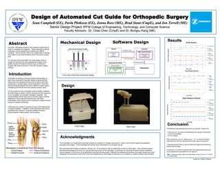
- 1. AbstractAbstract Design of Automated Cut Guide for Orthopedic SurgeryDesign of Automated Cut Guide for Orthopedic Surgery Sean Campbell (EE), Pavla Pletkova (EE), Jenna Ross (ME), Brad SSean Campbell (EE), Pavla Pletkova (EE), Jenna Ross (ME), Brad Stout (CmpE), and Jon Terrell (ME)tout (CmpE), and Jon Terrell (ME) Senior Design Project:Senior Design Project: IPFW College of Engineering, Technology, and Computer ScienceIPFW College of Engineering, Technology, and Computer Science Faculty Advisors: Dr. Chao Chen (CmpE) and Dr. Bongsu Kang (ME)Faculty Advisors: Dr. Chao Chen (CmpE) and Dr. Bongsu Kang (ME) IntroductionIntroduction DesignDesign Currently, orthopedic surgeons use numerous instruments in order to complete joint surgeries. These instruments require meticulous manual adjustments creating long, difficult surgeries. Due to this fact, there is an urgent need to develop new, easier to use instrumentation which will reduce surgery time. It is the goal of the Automated Cut Guide design team to create an instrument for knee replacement surgery which greatly reduces the need for manual input, provides the surgeon with ease of use and, in the end, shortens surgery duration. Orthopedic technology involving surgical cutting guides, to date, have consisted of manually altered components that require fine tune adjustment that could be tedious and time- consuming to correctly align in three dimensions. When two axes are properly aligned, the third is difficult to place without misaligning the first two that were already properly setup. For this project we have developed instrumentation, software, and technology to assist in primary femoral and tibia resections in non-navigated, and possibly navigated, surgeries. The instrumentation will be used only for Zimmer Legacy Posterior Stabilizing (LPS) surgical techniques and Total Knee Arthroplasty (TKA) incisions and is intended to replace manual tuning via wireless technology. Tolerances are in place to provide accuracy when aligning the cut guide wirelessly. Validation of the tolerances used will be completed with Zimmer’s Computer Assisted Solutions Electromagnetic Paddle system, during testing. AcknowledgmentsAcknowledgments The Automated Cut Guide team would like to thank our advisors Dr. Bongsu Kang and Dr. Chao Chen for their support and guidance throughout this project. Their knowledge and advice have contributed to our success thus far. We would also like to thank our sponsor, Zimmer, Inc., for providing us with an opportunity to work on this project. The continued support and technical assistance Zimmer, Inc. has provided has proven to be invaluable. In particular, we would like to thank Jackson Heavener, Senior Engineer I CAS Group, for his dedication and input into this project. Without his expertise and fortitude, this project would have never happened. We would like to also thank First Gear Engineering & Technology for allowing us to complete our system testing at their facilities. Necessary movements from the device: Varus/Valgus Flexion/Extension Distal/Proximal Anterior/Posterior Poster by: Patrick Huffman Front view of the final mechanical design. Mechanical DesignMechanical Design FE/AP Results 0 1 2 3 4 5 6 7 8 9 10 11 12 1 2 3 4 5 6 Test Trials 10 Deg Actual 10 Deg Theoretical 5 Deg Actual 5 Deg Theoretical 3 Deg Actual 3 Deg Theoretical 1 Deg Actual 1 Deg Theoretical AngleofRotation(Degrees) Varus/Valgus Results 0 1 2 3 4 5 6 1 2 3 4 5 6 7 Test Trials 5 Deg Actual 5 Deg Theoretical 3 Deg Actual 3 Deg Theoretical 1 Deg Actual 1 Deg Theoretical AngleofRotation(Degrees) Depth Resection Results 0.0 1.0 2.0 3.0 4.0 5.0 6.0 7.0 8.0 1 2 3 4 5 6 7 8 9 10 11 12 Test Trials 1mm Actual 1mm Theoretical 3mm Actual 3mm Theoretical 5mm Actual 5mm Theoretical 7mm Actual 7mm Theoretical DepthResection(mm) Software DesignSoftware Design ResultsResults Note: These test results reflect the testing done on April 10th and 11th of 2007 on a bread board. Front View Side View ConclusionConclusion The following requirements were set by our sponsor, Zimmer Inc. • ±2mm and ±2° accuracy for translational and angular movements • ±15mm of translation • ±10° of rotation With a maximum error of .150mm and 1° 17', our device functions well within the accuracy requirement for each type of movement. It was also proven that our device meets the range requirements by performing limit tests. In summary, our device functions within the requirements given and has exceeded the expectations of our sponsor.