
Recomendados
Mais conteúdo relacionado
Mais procurados
Mais procurados (20)
Semelhante a Landing Gear
Semelhante a Landing Gear (20)
Último
Último (20)
Landing Gear
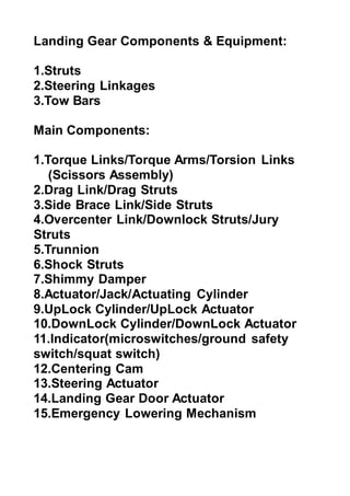
- 1. Landing Gear Components & Equipment: 1.Struts 2.Steering Linkages 3.Tow Bars Main Components: 1.Torque Links/Torque Arms/Torsion Links (Scissors Assembly) 2.Drag Link/Drag Struts 3.Side Brace Link/Side Struts 4.Overcenter Link/Downlock Struts/Jury Struts 5.Trunnion 6.Shock Struts 7.Shimmy Damper 8.Actuator/Jack/Actuating Cylinder 9.UpLock Cylinder/UpLock Actuator 10.DownLock Cylinder/DownLock Actuator 11.Indicator(microswitches/ground safety switch/squat switch) 12.Centering Cam 13.Steering Actuator 14.Landing Gear Door Actuator 15.Emergency Lowering Mechanism
- 2. 1.Torque Links/Torque Arms/Torsion Links (Scissors Assembly) It Maintain wheel and axle in a correct alinged position in relation to the strut (misalignment corrected by adding/installing a spacer or shim of different thickness). Prevent ram of a piston turning in the struts. Restrict the extension of the piston during the extension of the struts. FUNCTION: The hinged link between the piston and cylinder of an oleo-type landing gear shock absorber. The torque links allow the piston to move freely in and out of the landing gear cylinder, but prevent it rotating. The torque links can be adjusted to achieve and maintain the correct wheel alignment.
- 3. (Fig.1) 2.Drag Link/Drag Struts: Stabilizing the Landing gear and support the aircraft structure longitudinally. FUNCTION: A drag strut is used to restrain against the pivot action built into the trunnion attachment (Fig.2) 3.Side Brace Link/Side Struts: Stabilizing the Landing Gear and support the aircraft laterally
- 4. (Fig.3) 4.Overcenter Link/Downlock Struts/Jury Struts Holds the drag link and the side brace in the ‘DOWN’ and ‘LOCKED’ position by applying pressure to the center pivot joint in a drag or side brace link. Operates hydraulically by bungee cylinder or mechanically by bungee springs. FUNCTION: The side brace assembly includes a jury strutvwhich functions to lock the side brace assembly with the landing gear in the extended position. (Fig.4)
- 5. 5.Trunnion The trunnion is a fixed structural extension of the upper strut cylinder with bearing surfaces that allow the entire gear assembly to move. It is attached to aircraft structure in such a way that the gear can pivot from the vertical position required for landing and taxi to the stowed position used during flight. Supported at its end by bearing/bushing assemblies,which allow the gear to pivot during retraction and extension (the struts form the cylinder for the Oleo pneumatic shock absorber). FUNCTION: The purpose of a trunnion is to structurally support the landing gear in bearing the weight of the aircraft when it is not flying. (Fig.5)
- 6. 6.Shock Struts A typical pneumatic/hydraulic shock strut uses compressed air or nitrogen combined with hydraulic fluid to absorb and dissipate shock loads. It is sometimes referred to as an air/oil or oleo strut. A shock strut is constructed of two telescoping cylinders or tubes that are closed on the external ends. The upper cylinder is fixed to the aircraft and does not move. The lower cylinder is called the piston and is free to slide in and out of the upper cylinder.Two chambers are formed. The lower chamber is always filled with hydraulic fluid and the upper chamber is filled with compressed air or nitrogen. An orifice located between the two cylinders provides a passage for the fluid from the bottom chamber to enter the top cylinder chamber when the strut is compressed. Vertical member of the landing gear assembly that contains the shock absorbing mechanism. FUNCTION: Absorbs and dissipating landing shocks incorporates of a telescopic tube mechanism which absorbs landing
- 7. shocks but resist re-bound and at the same time protects the aircraft structure. Controlling the re-bound(spring back or recoil)movement. Provi ding cushionin g effects during taxiing. (Fig.6) 7.Shimmy Damper A shimmy damper uses a cylinder filled with hydraulic fluid or a rubber/lubricant combination to prevent rapid movement of the nosewheel, while not interfering with slower operations. Hydraulic snubbing unit that reduces the tendency of the nose or tail wheel oscillate from side to side (rapid oscillation).
- 8. FUNCTION: A shimmy damper uses a cylinder filled with hydraulic fluid or a rubber/lubricant combination to prevent rapid movement of the nosewheel, while not interfering with slower operations. It turns the airplane, and the fluid squirts from one end of the cylinder to the other. At higher speeds, the fluid can’t get through as fast as the nosewheel wants to shimmy, and the nosewheel is stabilized, preventing shakin g. (Fig.7) 8.Actuator/Jack/Actuating Cylinder
- 9. Landing Gear Retraction Actuators are designed to provide retraction and extension forces while maintaining light weight and reliability. Raise and lowering the landing gear.May also used as a Downlock mechanism(continous application of pressure). Retraction actuators are manufactured from complete hog outs or finish machined from forgings to a one piece body. Housings are commonly made out of stainless steel for strength and anti-corrosive properties. High strength and wear resistant materials are utilized for the piston, end gland, and bearings to ensure longevity and reliable service without the need for overhauls or scheduled maintenance. FUNCTION: The landing gear is rotated about a pivot by an extend/retract actuator. To retract the landing gear, an unlock actuator pulls the lock-stay from over-center, which enables the extend/retract actuator to retract the landing gear to the stowed position. Both the extend/retract and unlock actuators are typically hydraulically powered. (Fig.8)
- 10. 9.UpLock Cylinder/UpLock Actuator Locking the landing gear in ‘UP’ and ‘LOCK’ position 10.DownLock Cylinder/DownLock Actuator Locking the landing gear in ‘DOWN’ and ‘LOCK’ p o s i t i o n (Fi g. 9) 11.Indicator(microswitches/ground safety switch/squat switch)
- 11. Means of providing cockpit indication with regards to the landing gear position,either ‘UP’ and ‘LOCKED’,’DOWN’ and ‘Locked’ or in transition and ‘NOT LOCKED’. A landing gear squat switch, or safety switch, is found on most aircraft. This is a switch positioned to open and close depending on the extension or compression of the main landing gear strut. The squat switch is wired into any number of system operating circuits. One circuit prevents the gear from being retracted while the aircraft is on the ground. There are different ways to achieve this lock-out. A solenoid that extends a shaft to physically disable the gear position selector is one such method found on many aircraft. FUNCTION: (Squat Switch) The squat switch is essentially a sensor that senses if the weight of the aircraft is resting on the gear.The squat switch is wired into any number of system operating circuits. One circuit prevents the gear from being retracted while the aircraft is on the ground. (Ground Safety Switch)
- 12. A switch in the landing gear that prevents the inadvertent retraction of landing gear on the ground. This switch usually is located in the port landing gear. (Fig.10)
- 13. 12. Ce nte rin g Ca m Aligning the nose wheel before retracted to ‘UP’ and back to its wheel well compartment A cam in the nose-gear shock strut that causes the piston to center when the strut fully extends. When the aircraft takes off and the strut extends, the wheel is straightened in its fore-and-aft position so it can be retracted into the wheel well. FUNCTION: The centering cam forces the nosewheel straight back with the strut before it is retracted into the nose wheel well.
- 14. (Fig.11 ) 13.Steering Actuator Allowing the pilot to control or steer the aircraft by means of NLG wheel assembly for taxiing. Nose Wheel Steering Actuators work in tandem to provide linear push/pull forces for aircraft steering. Actuators are sized for regional jets and large business jets. (Fig .12)
- 15. 14.Landing Gear Door Actuator Allowing the opening or closing of landing gear door (main and nose landing gear). FUNCTION: When the doors are fully open, the door actuator engages the plungers of both sequence valves to open the valves. (FIG.13) 15.Emergen cy Lowering Mechanism Providing the means of lowering down the landing gear in the event of normal extension system fails
- 16. (under FAR 23.729). FUNCTION: A device in an aircraft landing gear system that absorbs the landing shock, which occurs when an aircraft touches down when landing or during taxiing. (Fig.14) Materials Of Landing Gear The materials used for these components of landing gear are composed of mainly High Strength Steels,Titanium,Aluminium And Magnesium.
- 17. High Strength Steel High Strength Steel have strength and stiffness. High Strength to volume ratio is the main factor which makes it important for the landing gear. Titanium The titanium has high strength and low density used as for weight saving. The main titanium alloy is Ti-5Al-5V-5Mo-3Cr,which is used in the main components of landing gear. Aluminium Modern aircraft consists of approximately 70% of aluminium alloys.It has relatively low cost,light in weight and can be heat treated to Stength level. Aluminium 7075 is used for the Landing Gear in helicopters because it is strong,with a strength comparable to many steels, and has good fatigue strength. Possible Failures Of Landing Gear 1.Fatigue Cracking Failure 2.Stress Corrosion Cracking
- 18. 3.Dynamic Failure 4.Landing Gear Spring Failure 5.Wheel Failure 1.Fatigue Cracking Failure: Usually aircrafts and military experience serious damages and the fatigues. Equat ions used for analy zing: 1.Paris Equatio n: 2.Forman Equation: 3.Walker Equation: Effective Stress=(1-R)m X Maximum Stress 2.Stress Corrosion Cracking: SCC is defined as the crack propogation caused by a synergy between a corrosive environment and a mechanical tensile stress.
- 19. Stress Corrosion Crack Growth 3.Dynamic Failure When an aircraft lands on the tricycle landing gear(the nose wheel and both landing gear) and the load affected by the ground/pavement response are distributed on them Numerical test showing stress analysis to define the dynamic characteristics of the landing gear,with the vertical-drop test Problem of contact between mating components and surfaces of fractures Investigation into kinematics of the landing gear. Investigation into the problem of dissipation of energy in the whole system. Checking of possible failure influence on the structure behaviour. 4.Landing Gear Spring Failure
- 20. T he Mic ro cra cks act ed as str ess con cen trat ion as wel l initiation crack site leading the springs to fracture due to fatigue. 5.Wheel Failure During landing,wheels are exposed to a lot of pressure.
- 21. Through this,overpressure may occur.This could have the effect that the thread is thrown off. Investigation photos show the damage was limited to tries and rims only