SlideShare uma empresa Scribd logo
1 de 12
Baixar para ler offline
Quick return mechanism:Name of Experiment
Apparatus:
Quick return mechanism
Figure:
:Abstract
In this mechanism it must be founded the max velocity and min velocity to obtained
the max force required
:Theory
:Mechanism
When one of the links of a kinematics chain is fixed, the chain is known as
mechanisms. It may
be used for transmitting or transforming motion e.g. engine indicators, typewriter etc.
Types:
a) Simple mechanism
b) Compound mechanism
a) Simple Mechanism:
A mechanism with four links is known as simple mechanism.
b) Compound Mechanism:
The mechanism with more than four links is known as compound mechanism
Machine:
When a mechanism is required to transmit power or to some particular type of work;
it then becomes a machine.
In such cases the links is to be designed to withstand the force (both static and kinetic
safely) A little consideration will show that a mechanism may be regarded as a
machine in which each part is reduced to the simplest form to transmit the required
motion
Inversion:
Sometimes, one of the links in a kinematic chain is fixed. In such a case, we may
obtain as many mechanisms as the links of the kinematic chain. This method of
obtaining different mechanisms by fixing in turns different links in a kinematic chain,
is known as inversion
Types of kinematic chains:
The most important kinematic chains are those which consist of four lower pairs, each
pair being
a sliding pair or a turning pair. The following types of kinematic chain are important
from subject
point of view:
a. four bar chain or quadratic cycle chain
1. Beam engine
2. Coupling rod of locomotive
3. Watt’s indicator mechanism
b. Single slider crank chain
1. Pendulum pump
2. Oscillating cylinder engine
Quick return motion mechanism.3
4. Rotary I.C. engine (Gnome engine)
c. Double slider crank chain
3. Crank and slotted lever quick return motion mechanism:
This mechanism is mostly used in shaping machine, slotting machine and in rotary
internal
combustion engine. The mechanism consists of a fixed link AC as shown in fig
The driving crank revolves with uniform angular speed about the fixed center C.A
sliding block attached to the crank pin at E slides along the slotted bar AP and thus
causes AP to oscillate about
The fixed center A. A short link bar PR transmit the motion from AP to the ram which
carries the
tool and reciprocates along the line of stroke R 1 R2. The line of stroke of the ram (R
1 R2) is
perpendicular to AO produced. In the extreme position, AP and AP2 are tangential to
the circle
and the cutting tool is at the end of the stroke. The cutting stroke occurs when the
crank rotates
from the position CB1 to CB2 (or through an angle beta) in the clockwise direction.
The return
stroke occurs when the crank rotates from the position CB2to CB1 (or through an
angle alpha) in
the clockwise direction
Working of Quick Return Mechanism:
A quick return mechanism such as the one seen below is used where there is a need to
convert rotary motion into reciprocating motion. As the disc rotates the black slide
moves forwards and backwards. Many machines have this type of mechanism and in
the school workshop the best
example is the shaping machine.
Purpose:
It is often desirable to reduce the non-productive time in machining so we use quick
return mechanism to let the backward stroke operate at a higher speed than forward
stroke.
Applications:
Presses:
The Whitworth quick return mechanism has been modified and used for constructing
high velocity impacting press. The impacting press drive consists of a Whitworth
quick return mechanism consisting of a crank and a drive arm together with a variable
speed dc. motor, a flywheel, bearings, etc. The end of the drive arm is attached by a
connecting rod to a cycloidal cam. In single cycle operation, the cam is made to
engage with an upper platen (or ram) which impacts the work piece. The upper platen
and cam are both mounted on multi rod supports with linear ball bushings. A brake is
provided on the flywheel for emergency purposes. The high speed impacting presses
are subject to severe dynamic forces when operating at speeds of 200 rpm and greater.
Although the mechanism has been designed to withstand operation at higher
frequencies,the loads transmitted to the building foundations because unwanted
vibrations and noise.
Shaper machine:
Shaper consists of a hollow machine bed made of cast iron which rests on the ground.
Inside the hollow portion the machine drive mechanism is housed. This mechanism is
called slotted lever quick return mechanism and it drives a horizontal ram which
reciprocates in the guide ways provided on the top surface of the machine frame.
Since useful work is done only during the forward stroke of ram, the mechanism
driving the ram is so designed that the return stroke is completed in much less time
than the forward stroke. The slotted lever quick return mechanism is shown in Figs.
T The crank AB (of adjustable length R) rotates with a uniform angular speed. The
crank pin B is in the shape of a die block which is free to slide inside the slot in the
slotted lever OBC. This slotted lever is pivoted at O and the other end C is connected
to the ram by a short link arm as shown in Fig. (a). When the crank AB rotates
clockwise from position AB1to AB2, the ram moves forward from left to right and
when it rotates from position AB2to AB1the ram returns back to its original position.
Clearly the time taken to complete forward stroke is proportional to angle α (refer to
Fig. (b)) and the return stroke is completed in less time which is proportional to angle
β.
C
A
O
B
O`'
L2 L1
𝑂𝐴 = 𝑂` 𝐴` = 4 ∙ 5𝑐𝑚
𝑂`
𝐵 = 19𝑐𝑚
𝑂`
𝐴`
= 𝑂`
𝐴 = 15𝑐𝑚
𝑂𝐴` = 𝑂𝐴 = 4 ∙ 5𝑐𝑚
𝑂` 𝐴` = 6 ∙ 5𝑐𝑚
the rules of experience practicethe rules of experience theoretically
𝒅𝒙 𝒅𝒕⁄ = 𝒗
∆𝒙 ∆𝒕⁄ = 𝒗
∆𝑥
∆𝜃
∙
∆𝜃
∆𝑡
= 𝑣
∆2 𝑥
∆𝜃2
= 𝑎
𝑉𝐴 = 𝜔 ∗ 𝑂𝐴
𝑉𝐴 = 𝐶 ∗ 𝑂𝐴
𝐿1
𝐿2
=
𝐿 𝐴
𝐿 𝐴`
𝑉𝑏 = 𝑉𝐶
𝑉𝑎 = 𝑉𝑎`
𝑂`
𝐵
𝑂` 𝐴`
=
𝑉𝑏
𝑉𝑎`
𝑂` 𝐵
𝑂` 𝐴`
=
𝑉𝐶
𝑉𝑎
1
2
𝑚𝑣𝑐
2 = 𝐹 ∙ 𝐿1
𝑉𝐴` = 𝑂`
𝐴`
∗ 𝜔
𝐴`
𝑜`
𝐴`
𝑜`
𝐴`
𝑂`
𝐴`
B
The table shows the practical aspect of the experience with the reading process calculations
NO Ө x ∆Ө ∆x ∆x∕∆Ө=v
1 0 0 0 0 0
2 10 0.05 10 0.19 0.019
3 20 0.24 10 0.4 0.04
4 30 0.64 10 0.55 0.055
5 40 1.19 10 0.67 0.067
6 50 1.86 10 0.94 0.094
7 60 2.8 10 0.9 0.09
8 70 3.7 10 0.76 0.076
9 80 4.46 10 0.64 0.064
10 90 5.1 10 0.43 0.043
11 100 5.53 10 0.32 0.032
12 110 5.85 10 0.15 0.015
13 120 6 10 0.07 0.007
14 130 6.07 10 -0.02 -0.002
15 140 6.05 10 -0.09 -0.009
16 150 5.96 10 -0.16 -0.016
17 160 5.8 10 -0.16 -0.016
18 170 5.64 10 -0.22 -0.022
19 180 5.42 10 -0.26 -0.026
20 190 5.16 10 -0.29 -0.029
21 200 4.87 10 -0.32 -0.032
22 210 4.55 10 -0.34 -0.034
23 220 4.21 10 -0.33 -0.033
24 230 3.88 10 -0.37 -0.037
25 240 3.51 10 -0.39 -0.039
26 250 3.12 10 -0.38 -0.038
27 260 2.74 10 -0.39 -0.039
28 270 2.35 10 -0.35 -0.035
29 280 2 10 -0.38 -0.038
30 290 1.62 10 -0.34 -0.034
31 300 1.28 10 -0.36 -0.036
32 310 0.92 10 -0.28 -0.028
33 320 0.64 10 -0.27 -0.027
34 330 0.37 10 -0.353 -0.0353
35 340 0.017 10 0.033 0.0033
36 350 0.05 10 -0.05 -0.005
37 360 0 0 0 0
Theoretical calculations:
ω = 𝐜𝐨𝐧𝐬𝐭𝐚𝐧𝐭
VA` = 6.5 ∗ 10−2 = 0 ∙ 065
𝑉𝐴` = 𝑂` 𝐴` ∗ 𝜔
𝑉𝐴` = 4 ∙ 5 ∗ 10−2 = 0 ∙ 045
Resultant:
Max and min velocity
Experience practiceA-
Max
NO Ө x ∆Ө ∆x ∆x∕∆Ө=v
6 50 1.86 10 0.94 0.094
Min
NO Ө x ∆Ө ∆x ∆x∕∆Ө=v
25 240 3.51 10 -0.39 -0.039
27 260 2.74 10 -0.39 -0.039
B-Theoretical
MAX
VA` = O`A` ∗ ω
VA` = 6.5 ∗ 10−2
= 0 ∙ 065
MIN
𝑉𝐴` = 𝑂` 𝐴` ∗ 𝜔
𝑉𝐴` = 4 ∙ 5 ∗ 10−2 = 0 ∙ 045
1.The relationship between ; (x, Ө)
2.The relationship between ; (∆x∕∆Ө, Ө)
0
1
2
3
4
5
6
7
0 50 100 150 200 250 300 350 400
X
Ө
-0.06
-0.04
-0.02
0
0.02
0.04
0.06
0.08
0.1
0.12
0 50 100 150 200 250 300 350 400
∆x∕∆Ө
Ө
Discussions:
1. What are the max and min velocity for milling machine and what the factors
required?
The speed depends on the type of metal and the amount of feed
Calculation for Cutting Speed, Spindle Speed and Feed
1.The speed is maximum when the machine is free from work. There is no feed. If the
navel is high and the feeding process occurs, problems will occur in either the cutting
pen or the metal to be operated
2. Be the speed min in a way to go to work when occur process feeding the metal
operator be speed slow to keep the metal operator and keep pens pieces in order to not
occur vibrations in the machine
The factors required for milling machine
1 .The type of metal used in the machine components, the teeth of the wreck,
the machine cover and thickness
2 .The type of treatment for the metal used in manufacturing, the safety factor
of the machine and the extent of the operator's experience
3 .Test results and workplace of the machine Do you agree to the terms of
use
4 .The capacity of the motor and its ability to operate continuously
2. Find the max displacement with max force
1
2
𝑚𝑣𝑐
2 = 𝐹 ∙ 𝐿1
In order to derive the force vectors of these mechanisms, one must approach a
mechanical design consisting of both kinematic and dynamic analyses.
Kinematic Analysis
Breaking the mechanism up into separate vectors and components allows us to create
a kinematic analysis that can solve for the maximum velocity, acceleration, and force
the mechanism is capable of in three-dimensional space Most of the equations
involved in the quick return mechanism setup originate from Hamilton's principle
The position of the arm can be found at different times using the substitution of
Euler's formula
Into the different components that have been pre-determined, according to the setup.
This substitution can solve for various radii and components of the displacement of
the arm at different values. Trigonometry is needed for the complete understanding of
the kinematic analyses of the mechanism, where the entire design can be transcribed
onto a plane layout, highlighting all of the vector components.
An important concept for the analysis of the velocity of the disc relative to the arm is
the angular velocity of the disc:
If one desires to calculate the velocity, one must derive the angles of interaction at a
single moment of time, making this equation useful.
Dynamic Analysis
In addition to the kinematic analysis of a quick return mechanism, there is a dynamic
analysis present. At certain lengths and attachments, the arm of the mechanism can be
evaluated and then adjusted to certain preferences. For example, the differences in the
forces acting upon the system at an instant can be represented by Alembert's principle.
Depending on the structural design of the quick return mechanism, the law of cosines
can be used to determine the angles and displacements of the arm. The ratio between
the working stroke (engine) and the return stroke can be simplified through the
manipulation of these concepts. Despite similarities between quick return
mechanisms, there are many different possibilities for the outline of all forces, speeds,
lengths, motions, functions, and vectors in a mechanism.
Baghdad University
College of Engineering
Department of Mechanical Engineering
Name of Experiment
"Quick return mechanism"
Preparation:
Saif al-Din Ali Madi
The second phase
Group "A"

Mais conteúdo relacionado

Mais procurados

Theory of Machine and Mechanisms (Gears)
Theory of Machine and Mechanisms (Gears)Theory of Machine and Mechanisms (Gears)
Theory of Machine and Mechanisms (Gears)Abhishek Attal
 
Concentric springs, surge phenomenon in spring, helical torsion, spiral spring
Concentric springs, surge phenomenon in spring, helical torsion, spiral springConcentric springs, surge phenomenon in spring, helical torsion, spiral spring
Concentric springs, surge phenomenon in spring, helical torsion, spiral springvaibhav tailor
 
The four bar chain mechanism
The four bar chain mechanismThe four bar chain mechanism
The four bar chain mechanismMakwanaMilan1
 
Spur gear and design of spur gear
Spur gear and design of spur gearSpur gear and design of spur gear
Spur gear and design of spur gearYash Shah
 
Module 4 gears
Module 4 gearsModule 4 gears
Module 4 gearstaruian
 
Power screw (machine design & industrial drafting )
Power screw (machine design & industrial drafting )Power screw (machine design & industrial drafting )
Power screw (machine design & industrial drafting )Digvijaysinh Gohil
 
4 independed suspension system
4 independed suspension system4 independed suspension system
4 independed suspension systemshaikusmanshag
 
CAM AND FOLLOWER
CAM AND FOLLOWERCAM AND FOLLOWER
CAM AND FOLLOWERAJAY SAVITA
 
Design of Gear Box
Design of Gear BoxDesign of Gear Box
Design of Gear BoxAbhi23396
 
1 b. Machine design - Prefered numbers, asthetic and ergonomic design
1 b. Machine design - Prefered numbers, asthetic and ergonomic design1 b. Machine design - Prefered numbers, asthetic and ergonomic design
1 b. Machine design - Prefered numbers, asthetic and ergonomic designDr.R. SELVAM
 
INVERSION OF MECHANISM
INVERSION OF MECHANISMINVERSION OF MECHANISM
INVERSION OF MECHANISMCHMURLIDHAR
 
Belt, rope and chain drives
Belt, rope and chain drivesBelt, rope and chain drives
Belt, rope and chain drivesMANJUNATH N
 

Mais procurados (20)

Theory of Machine and Mechanisms (Gears)
Theory of Machine and Mechanisms (Gears)Theory of Machine and Mechanisms (Gears)
Theory of Machine and Mechanisms (Gears)
 
Static Force Analysis
Static Force AnalysisStatic Force Analysis
Static Force Analysis
 
KOM-UNIT-1-BASICS OF MECHANISMS
KOM-UNIT-1-BASICS OF MECHANISMSKOM-UNIT-1-BASICS OF MECHANISMS
KOM-UNIT-1-BASICS OF MECHANISMS
 
Concentric springs, surge phenomenon in spring, helical torsion, spiral spring
Concentric springs, surge phenomenon in spring, helical torsion, spiral springConcentric springs, surge phenomenon in spring, helical torsion, spiral spring
Concentric springs, surge phenomenon in spring, helical torsion, spiral spring
 
Design and Drawing of CAM profiles
Design and Drawing of CAM profilesDesign and Drawing of CAM profiles
Design and Drawing of CAM profiles
 
The four bar chain mechanism
The four bar chain mechanismThe four bar chain mechanism
The four bar chain mechanism
 
Spur gear and design of spur gear
Spur gear and design of spur gearSpur gear and design of spur gear
Spur gear and design of spur gear
 
Module 4 gears
Module 4 gearsModule 4 gears
Module 4 gears
 
Power screw (machine design & industrial drafting )
Power screw (machine design & industrial drafting )Power screw (machine design & industrial drafting )
Power screw (machine design & industrial drafting )
 
4 independed suspension system
4 independed suspension system4 independed suspension system
4 independed suspension system
 
CAM AND FOLLOWER
CAM AND FOLLOWERCAM AND FOLLOWER
CAM AND FOLLOWER
 
Belts and Rope Drives
Belts and Rope DrivesBelts and Rope Drives
Belts and Rope Drives
 
Screw jack
Screw jackScrew jack
Screw jack
 
Design of Gear Box
Design of Gear BoxDesign of Gear Box
Design of Gear Box
 
Beam engine Mechanism
Beam engine MechanismBeam engine Mechanism
Beam engine Mechanism
 
1 b. Machine design - Prefered numbers, asthetic and ergonomic design
1 b. Machine design - Prefered numbers, asthetic and ergonomic design1 b. Machine design - Prefered numbers, asthetic and ergonomic design
1 b. Machine design - Prefered numbers, asthetic and ergonomic design
 
INVERSION OF MECHANISM
INVERSION OF MECHANISMINVERSION OF MECHANISM
INVERSION OF MECHANISM
 
Classification of Bearings
Classification of BearingsClassification of Bearings
Classification of Bearings
 
Belt, rope and chain drives
Belt, rope and chain drivesBelt, rope and chain drives
Belt, rope and chain drives
 
kinematic synthesis
kinematic synthesiskinematic synthesis
kinematic synthesis
 

Semelhante a Quick return mechanism

Design of recumbent elliptical trainer
Design of  recumbent elliptical trainerDesign of  recumbent elliptical trainer
Design of recumbent elliptical trainerdaveson700
 
Quick return mechanism11
Quick return mechanism11Quick return mechanism11
Quick return mechanism11Saif al-din ali
 
Automatic Generation Control
Automatic Generation ControlAutomatic Generation Control
Automatic Generation ControlMINAL RADE
 
Paper analysis GTU KDM
Paper analysis GTU KDM Paper analysis GTU KDM
Paper analysis GTU KDM Takshil Gajjar
 
Finite Element Analysis of Shaft of Centrifugal Pump
Finite Element Analysis of Shaft of Centrifugal PumpFinite Element Analysis of Shaft of Centrifugal Pump
Finite Element Analysis of Shaft of Centrifugal PumpIOSR Journals
 
Theory of Machine-I Lab DBATU manual.pdf
Theory of Machine-I  Lab DBATU manual.pdfTheory of Machine-I  Lab DBATU manual.pdf
Theory of Machine-I Lab DBATU manual.pdfSachinShinde394412
 
Synthesis of Mechanism
Synthesis of MechanismSynthesis of Mechanism
Synthesis of MechanismR A Shah
 
Robust control strategies for an electric motor driven accumulator with elast...
Robust control strategies for an electric motor driven accumulator with elast...Robust control strategies for an electric motor driven accumulator with elast...
Robust control strategies for an electric motor driven accumulator with elast...ISA Interchange
 
Field_Oriented_Control_Induction_Machine
Field_Oriented_Control_Induction_MachineField_Oriented_Control_Induction_Machine
Field_Oriented_Control_Induction_MachineHelion Dhrimaj
 
Dynamics velocity diagrams
Dynamics velocity diagramsDynamics velocity diagrams
Dynamics velocity diagramsNasir Ahmad
 
Modeling analysis of transient stability of thermal power station jamshoro us...
Modeling analysis of transient stability of thermal power station jamshoro us...Modeling analysis of transient stability of thermal power station jamshoro us...
Modeling analysis of transient stability of thermal power station jamshoro us...sunny katyara
 
Modeling and simulation of vehicle windshield wiper system using h infinity l...
Modeling and simulation of vehicle windshield wiper system using h infinity l...Modeling and simulation of vehicle windshield wiper system using h infinity l...
Modeling and simulation of vehicle windshield wiper system using h infinity l...Mustefa Jibril
 
Dynamics lab manual
Dynamics lab manualDynamics lab manual
Dynamics lab manualDr. Ramesh B
 

Semelhante a Quick return mechanism (20)

Design of recumbent elliptical trainer
Design of  recumbent elliptical trainerDesign of  recumbent elliptical trainer
Design of recumbent elliptical trainer
 
Quick return mechanism11
Quick return mechanism11Quick return mechanism11
Quick return mechanism11
 
Automatic Generation Control
Automatic Generation ControlAutomatic Generation Control
Automatic Generation Control
 
Wce2013 pp1809 1814
Wce2013 pp1809 1814Wce2013 pp1809 1814
Wce2013 pp1809 1814
 
Dc motor calculations
Dc motor calculationsDc motor calculations
Dc motor calculations
 
Paper analysis GTU KDM
Paper analysis GTU KDM Paper analysis GTU KDM
Paper analysis GTU KDM
 
Finite Element Analysis of Shaft of Centrifugal Pump
Finite Element Analysis of Shaft of Centrifugal PumpFinite Element Analysis of Shaft of Centrifugal Pump
Finite Element Analysis of Shaft of Centrifugal Pump
 
E05222936
E05222936E05222936
E05222936
 
AutomaticClutchEAC
AutomaticClutchEACAutomaticClutchEAC
AutomaticClutchEAC
 
Theory of Machine-I Lab DBATU manual.pdf
Theory of Machine-I  Lab DBATU manual.pdfTheory of Machine-I  Lab DBATU manual.pdf
Theory of Machine-I Lab DBATU manual.pdf
 
Synthesis of Mechanism
Synthesis of MechanismSynthesis of Mechanism
Synthesis of Mechanism
 
Robust control strategies for an electric motor driven accumulator with elast...
Robust control strategies for an electric motor driven accumulator with elast...Robust control strategies for an electric motor driven accumulator with elast...
Robust control strategies for an electric motor driven accumulator with elast...
 
ControlsLab1
ControlsLab1ControlsLab1
ControlsLab1
 
I0413049055
I0413049055I0413049055
I0413049055
 
Field_Oriented_Control_Induction_Machine
Field_Oriented_Control_Induction_MachineField_Oriented_Control_Induction_Machine
Field_Oriented_Control_Induction_Machine
 
MMD Question Paper
MMD Question PaperMMD Question Paper
MMD Question Paper
 
Dynamics velocity diagrams
Dynamics velocity diagramsDynamics velocity diagrams
Dynamics velocity diagrams
 
Modeling analysis of transient stability of thermal power station jamshoro us...
Modeling analysis of transient stability of thermal power station jamshoro us...Modeling analysis of transient stability of thermal power station jamshoro us...
Modeling analysis of transient stability of thermal power station jamshoro us...
 
Modeling and simulation of vehicle windshield wiper system using h infinity l...
Modeling and simulation of vehicle windshield wiper system using h infinity l...Modeling and simulation of vehicle windshield wiper system using h infinity l...
Modeling and simulation of vehicle windshield wiper system using h infinity l...
 
Dynamics lab manual
Dynamics lab manualDynamics lab manual
Dynamics lab manual
 

Mais de Saif al-din ali

Nonlinear integral control for dc motor speed control with unknown and variab...
Nonlinear integral control for dc motor speed control with unknown and variab...Nonlinear integral control for dc motor speed control with unknown and variab...
Nonlinear integral control for dc motor speed control with unknown and variab...Saif al-din ali
 
Evaluation of thermal performance of a typical vapor compression refrigeratio...
Evaluation of thermal performance of a typical vapor compression refrigeratio...Evaluation of thermal performance of a typical vapor compression refrigeratio...
Evaluation of thermal performance of a typical vapor compression refrigeratio...Saif al-din ali
 
Refrigeration air conditioning laboratory Moist Air Properties and Air-Condi...
Refrigeration  air conditioning laboratory Moist Air Properties and Air-Condi...Refrigeration  air conditioning laboratory Moist Air Properties and Air-Condi...
Refrigeration air conditioning laboratory Moist Air Properties and Air-Condi...Saif al-din ali
 
Characteristics of a simply converging nozzle through which steam is passes
Characteristics of a simply converging nozzle through which steam is passesCharacteristics of a simply converging nozzle through which steam is passes
Characteristics of a simply converging nozzle through which steam is passesSaif al-din ali
 
Power plant steam condenser
Power plant steam condenser Power plant steam condenser
Power plant steam condenser Saif al-din ali
 
Performance of the four strokes diesel engine
Performance of the four strokes diesel enginePerformance of the four strokes diesel engine
Performance of the four strokes diesel engineSaif al-din ali
 
performance of the four strokes diesel engine
 performance of the four strokes diesel engine performance of the four strokes diesel engine
performance of the four strokes diesel engineSaif al-din ali
 
Introduction about i.c engine
Introduction about i.c engine Introduction about i.c engine
Introduction about i.c engine Saif al-din ali
 
Using the convergent steam nozzle type in the entrance
Using the convergent steam nozzle type in the entranceUsing the convergent steam nozzle type in the entrance
Using the convergent steam nozzle type in the entranceSaif al-din ali
 
Hybrid car Advanced vehicle technology
Hybrid car Advanced vehicle technologyHybrid car Advanced vehicle technology
Hybrid car Advanced vehicle technologySaif al-din ali
 
Nonlinear integral control for dc motor speed control
Nonlinear integral control for dc motor speed controlNonlinear integral control for dc motor speed control
Nonlinear integral control for dc motor speed controlSaif al-din ali
 
Weak and strong oblique shock waves2
Weak and strong oblique shock waves2Weak and strong oblique shock waves2
Weak and strong oblique shock waves2Saif al-din ali
 
Weak and strong oblique shock waves1
Weak and strong oblique shock waves1Weak and strong oblique shock waves1
Weak and strong oblique shock waves1Saif al-din ali
 
Oblique shock and expansion waves
Oblique shock and expansion wavesOblique shock and expansion waves
Oblique shock and expansion wavesSaif al-din ali
 

Mais de Saif al-din ali (20)

Nonlinear integral control for dc motor speed control with unknown and variab...
Nonlinear integral control for dc motor speed control with unknown and variab...Nonlinear integral control for dc motor speed control with unknown and variab...
Nonlinear integral control for dc motor speed control with unknown and variab...
 
Design problem
Design problemDesign problem
Design problem
 
Evaluation of thermal performance of a typical vapor compression refrigeratio...
Evaluation of thermal performance of a typical vapor compression refrigeratio...Evaluation of thermal performance of a typical vapor compression refrigeratio...
Evaluation of thermal performance of a typical vapor compression refrigeratio...
 
Refrigeration air conditioning laboratory Moist Air Properties and Air-Condi...
Refrigeration  air conditioning laboratory Moist Air Properties and Air-Condi...Refrigeration  air conditioning laboratory Moist Air Properties and Air-Condi...
Refrigeration air conditioning laboratory Moist Air Properties and Air-Condi...
 
Characteristics of a simply converging nozzle through which steam is passes
Characteristics of a simply converging nozzle through which steam is passesCharacteristics of a simply converging nozzle through which steam is passes
Characteristics of a simply converging nozzle through which steam is passes
 
Power plant steam condenser
Power plant steam condenser Power plant steam condenser
Power plant steam condenser
 
Performance of the four strokes diesel engine
Performance of the four strokes diesel enginePerformance of the four strokes diesel engine
Performance of the four strokes diesel engine
 
i.c engine
 i.c engine  i.c engine
i.c engine
 
Flow system control
Flow system controlFlow system control
Flow system control
 
Control servo motors
Control servo motors  Control servo motors
Control servo motors
 
Nozzles
NozzlesNozzles
Nozzles
 
performance of the four strokes diesel engine
 performance of the four strokes diesel engine performance of the four strokes diesel engine
performance of the four strokes diesel engine
 
Introduction about i.c engine
Introduction about i.c engine Introduction about i.c engine
Introduction about i.c engine
 
Flow system control
Flow system controlFlow system control
Flow system control
 
Using the convergent steam nozzle type in the entrance
Using the convergent steam nozzle type in the entranceUsing the convergent steam nozzle type in the entrance
Using the convergent steam nozzle type in the entrance
 
Hybrid car Advanced vehicle technology
Hybrid car Advanced vehicle technologyHybrid car Advanced vehicle technology
Hybrid car Advanced vehicle technology
 
Nonlinear integral control for dc motor speed control
Nonlinear integral control for dc motor speed controlNonlinear integral control for dc motor speed control
Nonlinear integral control for dc motor speed control
 
Weak and strong oblique shock waves2
Weak and strong oblique shock waves2Weak and strong oblique shock waves2
Weak and strong oblique shock waves2
 
Weak and strong oblique shock waves1
Weak and strong oblique shock waves1Weak and strong oblique shock waves1
Weak and strong oblique shock waves1
 
Oblique shock and expansion waves
Oblique shock and expansion wavesOblique shock and expansion waves
Oblique shock and expansion waves
 

Último

Employee leave management system project.
Employee leave management system project.Employee leave management system project.
Employee leave management system project.Kamal Acharya
 
Design For Accessibility: Getting it right from the start
Design For Accessibility: Getting it right from the startDesign For Accessibility: Getting it right from the start
Design For Accessibility: Getting it right from the startQuintin Balsdon
 
VIP Call Girls Palanpur 7001035870 Whatsapp Number, 24/07 Booking
VIP Call Girls Palanpur 7001035870 Whatsapp Number, 24/07 BookingVIP Call Girls Palanpur 7001035870 Whatsapp Number, 24/07 Booking
VIP Call Girls Palanpur 7001035870 Whatsapp Number, 24/07 Bookingdharasingh5698
 
A Study of Urban Area Plan for Pabna Municipality
A Study of Urban Area Plan for Pabna MunicipalityA Study of Urban Area Plan for Pabna Municipality
A Study of Urban Area Plan for Pabna MunicipalityMorshed Ahmed Rahath
 
Work-Permit-Receiver-in-Saudi-Aramco.pptx
Work-Permit-Receiver-in-Saudi-Aramco.pptxWork-Permit-Receiver-in-Saudi-Aramco.pptx
Work-Permit-Receiver-in-Saudi-Aramco.pptxJuliansyahHarahap1
 
Introduction to Serverless with AWS Lambda
Introduction to Serverless with AWS LambdaIntroduction to Serverless with AWS Lambda
Introduction to Serverless with AWS LambdaOmar Fathy
 
Call Girls In Bangalore ☎ 7737669865 🥵 Book Your One night Stand
Call Girls In Bangalore ☎ 7737669865 🥵 Book Your One night StandCall Girls In Bangalore ☎ 7737669865 🥵 Book Your One night Stand
Call Girls In Bangalore ☎ 7737669865 🥵 Book Your One night Standamitlee9823
 
Hazard Identification (HAZID) vs. Hazard and Operability (HAZOP): A Comparati...
Hazard Identification (HAZID) vs. Hazard and Operability (HAZOP): A Comparati...Hazard Identification (HAZID) vs. Hazard and Operability (HAZOP): A Comparati...
Hazard Identification (HAZID) vs. Hazard and Operability (HAZOP): A Comparati...soginsider
 
data_management_and _data_science_cheat_sheet.pdf
data_management_and _data_science_cheat_sheet.pdfdata_management_and _data_science_cheat_sheet.pdf
data_management_and _data_science_cheat_sheet.pdfJiananWang21
 
chapter 5.pptx: drainage and irrigation engineering
chapter 5.pptx: drainage and irrigation engineeringchapter 5.pptx: drainage and irrigation engineering
chapter 5.pptx: drainage and irrigation engineeringmulugeta48
 
ONLINE FOOD ORDER SYSTEM PROJECT REPORT.pdf
ONLINE FOOD ORDER SYSTEM PROJECT REPORT.pdfONLINE FOOD ORDER SYSTEM PROJECT REPORT.pdf
ONLINE FOOD ORDER SYSTEM PROJECT REPORT.pdfKamal Acharya
 
Unit 1 - Soil Classification and Compaction.pdf
Unit 1 - Soil Classification and Compaction.pdfUnit 1 - Soil Classification and Compaction.pdf
Unit 1 - Soil Classification and Compaction.pdfRagavanV2
 
Unleashing the Power of the SORA AI lastest leap
Unleashing the Power of the SORA AI lastest leapUnleashing the Power of the SORA AI lastest leap
Unleashing the Power of the SORA AI lastest leapRishantSharmaFr
 
Block diagram reduction techniques in control systems.ppt
Block diagram reduction techniques in control systems.pptBlock diagram reduction techniques in control systems.ppt
Block diagram reduction techniques in control systems.pptNANDHAKUMARA10
 
VIP Model Call Girls Kothrud ( Pune ) Call ON 8005736733 Starting From 5K to ...
VIP Model Call Girls Kothrud ( Pune ) Call ON 8005736733 Starting From 5K to ...VIP Model Call Girls Kothrud ( Pune ) Call ON 8005736733 Starting From 5K to ...
VIP Model Call Girls Kothrud ( Pune ) Call ON 8005736733 Starting From 5K to ...SUHANI PANDEY
 
UNIT - IV - Air Compressors and its Performance
UNIT - IV - Air Compressors and its PerformanceUNIT - IV - Air Compressors and its Performance
UNIT - IV - Air Compressors and its Performancesivaprakash250
 

Último (20)

Employee leave management system project.
Employee leave management system project.Employee leave management system project.
Employee leave management system project.
 
Design For Accessibility: Getting it right from the start
Design For Accessibility: Getting it right from the startDesign For Accessibility: Getting it right from the start
Design For Accessibility: Getting it right from the start
 
VIP Call Girls Palanpur 7001035870 Whatsapp Number, 24/07 Booking
VIP Call Girls Palanpur 7001035870 Whatsapp Number, 24/07 BookingVIP Call Girls Palanpur 7001035870 Whatsapp Number, 24/07 Booking
VIP Call Girls Palanpur 7001035870 Whatsapp Number, 24/07 Booking
 
A Study of Urban Area Plan for Pabna Municipality
A Study of Urban Area Plan for Pabna MunicipalityA Study of Urban Area Plan for Pabna Municipality
A Study of Urban Area Plan for Pabna Municipality
 
Work-Permit-Receiver-in-Saudi-Aramco.pptx
Work-Permit-Receiver-in-Saudi-Aramco.pptxWork-Permit-Receiver-in-Saudi-Aramco.pptx
Work-Permit-Receiver-in-Saudi-Aramco.pptx
 
Introduction to Serverless with AWS Lambda
Introduction to Serverless with AWS LambdaIntroduction to Serverless with AWS Lambda
Introduction to Serverless with AWS Lambda
 
Call Girls In Bangalore ☎ 7737669865 🥵 Book Your One night Stand
Call Girls In Bangalore ☎ 7737669865 🥵 Book Your One night StandCall Girls In Bangalore ☎ 7737669865 🥵 Book Your One night Stand
Call Girls In Bangalore ☎ 7737669865 🥵 Book Your One night Stand
 
Hazard Identification (HAZID) vs. Hazard and Operability (HAZOP): A Comparati...
Hazard Identification (HAZID) vs. Hazard and Operability (HAZOP): A Comparati...Hazard Identification (HAZID) vs. Hazard and Operability (HAZOP): A Comparati...
Hazard Identification (HAZID) vs. Hazard and Operability (HAZOP): A Comparati...
 
data_management_and _data_science_cheat_sheet.pdf
data_management_and _data_science_cheat_sheet.pdfdata_management_and _data_science_cheat_sheet.pdf
data_management_and _data_science_cheat_sheet.pdf
 
chapter 5.pptx: drainage and irrigation engineering
chapter 5.pptx: drainage and irrigation engineeringchapter 5.pptx: drainage and irrigation engineering
chapter 5.pptx: drainage and irrigation engineering
 
ONLINE FOOD ORDER SYSTEM PROJECT REPORT.pdf
ONLINE FOOD ORDER SYSTEM PROJECT REPORT.pdfONLINE FOOD ORDER SYSTEM PROJECT REPORT.pdf
ONLINE FOOD ORDER SYSTEM PROJECT REPORT.pdf
 
(INDIRA) Call Girl Meerut Call Now 8617697112 Meerut Escorts 24x7
(INDIRA) Call Girl Meerut Call Now 8617697112 Meerut Escorts 24x7(INDIRA) Call Girl Meerut Call Now 8617697112 Meerut Escorts 24x7
(INDIRA) Call Girl Meerut Call Now 8617697112 Meerut Escorts 24x7
 
Unit 1 - Soil Classification and Compaction.pdf
Unit 1 - Soil Classification and Compaction.pdfUnit 1 - Soil Classification and Compaction.pdf
Unit 1 - Soil Classification and Compaction.pdf
 
Unleashing the Power of the SORA AI lastest leap
Unleashing the Power of the SORA AI lastest leapUnleashing the Power of the SORA AI lastest leap
Unleashing the Power of the SORA AI lastest leap
 
(INDIRA) Call Girl Aurangabad Call Now 8617697112 Aurangabad Escorts 24x7
(INDIRA) Call Girl Aurangabad Call Now 8617697112 Aurangabad Escorts 24x7(INDIRA) Call Girl Aurangabad Call Now 8617697112 Aurangabad Escorts 24x7
(INDIRA) Call Girl Aurangabad Call Now 8617697112 Aurangabad Escorts 24x7
 
FEA Based Level 3 Assessment of Deformed Tanks with Fluid Induced Loads
FEA Based Level 3 Assessment of Deformed Tanks with Fluid Induced LoadsFEA Based Level 3 Assessment of Deformed Tanks with Fluid Induced Loads
FEA Based Level 3 Assessment of Deformed Tanks with Fluid Induced Loads
 
Block diagram reduction techniques in control systems.ppt
Block diagram reduction techniques in control systems.pptBlock diagram reduction techniques in control systems.ppt
Block diagram reduction techniques in control systems.ppt
 
VIP Model Call Girls Kothrud ( Pune ) Call ON 8005736733 Starting From 5K to ...
VIP Model Call Girls Kothrud ( Pune ) Call ON 8005736733 Starting From 5K to ...VIP Model Call Girls Kothrud ( Pune ) Call ON 8005736733 Starting From 5K to ...
VIP Model Call Girls Kothrud ( Pune ) Call ON 8005736733 Starting From 5K to ...
 
UNIT - IV - Air Compressors and its Performance
UNIT - IV - Air Compressors and its PerformanceUNIT - IV - Air Compressors and its Performance
UNIT - IV - Air Compressors and its Performance
 
Water Industry Process Automation & Control Monthly - April 2024
Water Industry Process Automation & Control Monthly - April 2024Water Industry Process Automation & Control Monthly - April 2024
Water Industry Process Automation & Control Monthly - April 2024
 

Quick return mechanism

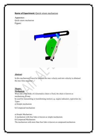
  • 1. Quick return mechanism:Name of Experiment Apparatus: Quick return mechanism Figure: :Abstract In this mechanism it must be founded the max velocity and min velocity to obtained the max force required :Theory :Mechanism When one of the links of a kinematics chain is fixed, the chain is known as mechanisms. It may be used for transmitting or transforming motion e.g. engine indicators, typewriter etc. Types: a) Simple mechanism b) Compound mechanism a) Simple Mechanism: A mechanism with four links is known as simple mechanism. b) Compound Mechanism: The mechanism with more than four links is known as compound mechanism
  • 2. Machine: When a mechanism is required to transmit power or to some particular type of work; it then becomes a machine. In such cases the links is to be designed to withstand the force (both static and kinetic safely) A little consideration will show that a mechanism may be regarded as a machine in which each part is reduced to the simplest form to transmit the required motion Inversion: Sometimes, one of the links in a kinematic chain is fixed. In such a case, we may obtain as many mechanisms as the links of the kinematic chain. This method of obtaining different mechanisms by fixing in turns different links in a kinematic chain, is known as inversion Types of kinematic chains: The most important kinematic chains are those which consist of four lower pairs, each pair being a sliding pair or a turning pair. The following types of kinematic chain are important from subject point of view: a. four bar chain or quadratic cycle chain 1. Beam engine 2. Coupling rod of locomotive 3. Watt’s indicator mechanism b. Single slider crank chain 1. Pendulum pump 2. Oscillating cylinder engine Quick return motion mechanism.3 4. Rotary I.C. engine (Gnome engine) c. Double slider crank chain
  • 3. 3. Crank and slotted lever quick return motion mechanism: This mechanism is mostly used in shaping machine, slotting machine and in rotary internal combustion engine. The mechanism consists of a fixed link AC as shown in fig The driving crank revolves with uniform angular speed about the fixed center C.A sliding block attached to the crank pin at E slides along the slotted bar AP and thus causes AP to oscillate about The fixed center A. A short link bar PR transmit the motion from AP to the ram which carries the tool and reciprocates along the line of stroke R 1 R2. The line of stroke of the ram (R 1 R2) is perpendicular to AO produced. In the extreme position, AP and AP2 are tangential to the circle and the cutting tool is at the end of the stroke. The cutting stroke occurs when the crank rotates from the position CB1 to CB2 (or through an angle beta) in the clockwise direction. The return stroke occurs when the crank rotates from the position CB2to CB1 (or through an angle alpha) in the clockwise direction
  • 4. Working of Quick Return Mechanism: A quick return mechanism such as the one seen below is used where there is a need to convert rotary motion into reciprocating motion. As the disc rotates the black slide moves forwards and backwards. Many machines have this type of mechanism and in the school workshop the best example is the shaping machine. Purpose: It is often desirable to reduce the non-productive time in machining so we use quick return mechanism to let the backward stroke operate at a higher speed than forward stroke. Applications: Presses: The Whitworth quick return mechanism has been modified and used for constructing high velocity impacting press. The impacting press drive consists of a Whitworth quick return mechanism consisting of a crank and a drive arm together with a variable speed dc. motor, a flywheel, bearings, etc. The end of the drive arm is attached by a connecting rod to a cycloidal cam. In single cycle operation, the cam is made to engage with an upper platen (or ram) which impacts the work piece. The upper platen and cam are both mounted on multi rod supports with linear ball bushings. A brake is provided on the flywheel for emergency purposes. The high speed impacting presses are subject to severe dynamic forces when operating at speeds of 200 rpm and greater. Although the mechanism has been designed to withstand operation at higher frequencies,the loads transmitted to the building foundations because unwanted vibrations and noise. Shaper machine: Shaper consists of a hollow machine bed made of cast iron which rests on the ground. Inside the hollow portion the machine drive mechanism is housed. This mechanism is called slotted lever quick return mechanism and it drives a horizontal ram which reciprocates in the guide ways provided on the top surface of the machine frame. Since useful work is done only during the forward stroke of ram, the mechanism driving the ram is so designed that the return stroke is completed in much less time than the forward stroke. The slotted lever quick return mechanism is shown in Figs.
  • 5. T The crank AB (of adjustable length R) rotates with a uniform angular speed. The crank pin B is in the shape of a die block which is free to slide inside the slot in the slotted lever OBC. This slotted lever is pivoted at O and the other end C is connected to the ram by a short link arm as shown in Fig. (a). When the crank AB rotates clockwise from position AB1to AB2, the ram moves forward from left to right and when it rotates from position AB2to AB1the ram returns back to its original position. Clearly the time taken to complete forward stroke is proportional to angle α (refer to Fig. (b)) and the return stroke is completed in less time which is proportional to angle β. C A O B O`' L2 L1
  • 6. 𝑂𝐴 = 𝑂` 𝐴` = 4 ∙ 5𝑐𝑚 𝑂` 𝐵 = 19𝑐𝑚 𝑂` 𝐴` = 𝑂` 𝐴 = 15𝑐𝑚 𝑂𝐴` = 𝑂𝐴 = 4 ∙ 5𝑐𝑚 𝑂` 𝐴` = 6 ∙ 5𝑐𝑚 the rules of experience practicethe rules of experience theoretically 𝒅𝒙 𝒅𝒕⁄ = 𝒗 ∆𝒙 ∆𝒕⁄ = 𝒗 ∆𝑥 ∆𝜃 ∙ ∆𝜃 ∆𝑡 = 𝑣 ∆2 𝑥 ∆𝜃2 = 𝑎 𝑉𝐴 = 𝜔 ∗ 𝑂𝐴 𝑉𝐴 = 𝐶 ∗ 𝑂𝐴 𝐿1 𝐿2 = 𝐿 𝐴 𝐿 𝐴` 𝑉𝑏 = 𝑉𝐶 𝑉𝑎 = 𝑉𝑎` 𝑂` 𝐵 𝑂` 𝐴` = 𝑉𝑏 𝑉𝑎` 𝑂` 𝐵 𝑂` 𝐴` = 𝑉𝐶 𝑉𝑎 1 2 𝑚𝑣𝑐 2 = 𝐹 ∙ 𝐿1 𝑉𝐴` = 𝑂` 𝐴` ∗ 𝜔 𝐴` 𝑜` 𝐴` 𝑜` 𝐴` 𝑂` 𝐴` B
  • 7. The table shows the practical aspect of the experience with the reading process calculations NO Ө x ∆Ө ∆x ∆x∕∆Ө=v 1 0 0 0 0 0 2 10 0.05 10 0.19 0.019 3 20 0.24 10 0.4 0.04 4 30 0.64 10 0.55 0.055 5 40 1.19 10 0.67 0.067 6 50 1.86 10 0.94 0.094 7 60 2.8 10 0.9 0.09 8 70 3.7 10 0.76 0.076 9 80 4.46 10 0.64 0.064 10 90 5.1 10 0.43 0.043 11 100 5.53 10 0.32 0.032 12 110 5.85 10 0.15 0.015 13 120 6 10 0.07 0.007 14 130 6.07 10 -0.02 -0.002 15 140 6.05 10 -0.09 -0.009 16 150 5.96 10 -0.16 -0.016 17 160 5.8 10 -0.16 -0.016 18 170 5.64 10 -0.22 -0.022 19 180 5.42 10 -0.26 -0.026 20 190 5.16 10 -0.29 -0.029 21 200 4.87 10 -0.32 -0.032 22 210 4.55 10 -0.34 -0.034 23 220 4.21 10 -0.33 -0.033 24 230 3.88 10 -0.37 -0.037 25 240 3.51 10 -0.39 -0.039 26 250 3.12 10 -0.38 -0.038 27 260 2.74 10 -0.39 -0.039 28 270 2.35 10 -0.35 -0.035 29 280 2 10 -0.38 -0.038 30 290 1.62 10 -0.34 -0.034 31 300 1.28 10 -0.36 -0.036 32 310 0.92 10 -0.28 -0.028 33 320 0.64 10 -0.27 -0.027 34 330 0.37 10 -0.353 -0.0353 35 340 0.017 10 0.033 0.0033 36 350 0.05 10 -0.05 -0.005 37 360 0 0 0 0
  • 8. Theoretical calculations: ω = 𝐜𝐨𝐧𝐬𝐭𝐚𝐧𝐭 VA` = 6.5 ∗ 10−2 = 0 ∙ 065 𝑉𝐴` = 𝑂` 𝐴` ∗ 𝜔 𝑉𝐴` = 4 ∙ 5 ∗ 10−2 = 0 ∙ 045 Resultant: Max and min velocity Experience practiceA- Max NO Ө x ∆Ө ∆x ∆x∕∆Ө=v 6 50 1.86 10 0.94 0.094 Min NO Ө x ∆Ө ∆x ∆x∕∆Ө=v 25 240 3.51 10 -0.39 -0.039 27 260 2.74 10 -0.39 -0.039 B-Theoretical MAX VA` = O`A` ∗ ω VA` = 6.5 ∗ 10−2 = 0 ∙ 065 MIN 𝑉𝐴` = 𝑂` 𝐴` ∗ 𝜔 𝑉𝐴` = 4 ∙ 5 ∗ 10−2 = 0 ∙ 045 1.The relationship between ; (x, Ө)
  • 9. 2.The relationship between ; (∆x∕∆Ө, Ө) 0 1 2 3 4 5 6 7 0 50 100 150 200 250 300 350 400 X Ө -0.06 -0.04 -0.02 0 0.02 0.04 0.06 0.08 0.1 0.12 0 50 100 150 200 250 300 350 400 ∆x∕∆Ө Ө
  • 10. Discussions: 1. What are the max and min velocity for milling machine and what the factors required? The speed depends on the type of metal and the amount of feed Calculation for Cutting Speed, Spindle Speed and Feed 1.The speed is maximum when the machine is free from work. There is no feed. If the navel is high and the feeding process occurs, problems will occur in either the cutting pen or the metal to be operated 2. Be the speed min in a way to go to work when occur process feeding the metal operator be speed slow to keep the metal operator and keep pens pieces in order to not occur vibrations in the machine The factors required for milling machine 1 .The type of metal used in the machine components, the teeth of the wreck, the machine cover and thickness 2 .The type of treatment for the metal used in manufacturing, the safety factor of the machine and the extent of the operator's experience 3 .Test results and workplace of the machine Do you agree to the terms of use 4 .The capacity of the motor and its ability to operate continuously
  • 11. 2. Find the max displacement with max force 1 2 𝑚𝑣𝑐 2 = 𝐹 ∙ 𝐿1 In order to derive the force vectors of these mechanisms, one must approach a mechanical design consisting of both kinematic and dynamic analyses. Kinematic Analysis Breaking the mechanism up into separate vectors and components allows us to create a kinematic analysis that can solve for the maximum velocity, acceleration, and force the mechanism is capable of in three-dimensional space Most of the equations involved in the quick return mechanism setup originate from Hamilton's principle The position of the arm can be found at different times using the substitution of Euler's formula Into the different components that have been pre-determined, according to the setup. This substitution can solve for various radii and components of the displacement of the arm at different values. Trigonometry is needed for the complete understanding of the kinematic analyses of the mechanism, where the entire design can be transcribed onto a plane layout, highlighting all of the vector components. An important concept for the analysis of the velocity of the disc relative to the arm is the angular velocity of the disc: If one desires to calculate the velocity, one must derive the angles of interaction at a single moment of time, making this equation useful. Dynamic Analysis In addition to the kinematic analysis of a quick return mechanism, there is a dynamic analysis present. At certain lengths and attachments, the arm of the mechanism can be evaluated and then adjusted to certain preferences. For example, the differences in the forces acting upon the system at an instant can be represented by Alembert's principle. Depending on the structural design of the quick return mechanism, the law of cosines can be used to determine the angles and displacements of the arm. The ratio between the working stroke (engine) and the return stroke can be simplified through the manipulation of these concepts. Despite similarities between quick return mechanisms, there are many different possibilities for the outline of all forces, speeds, lengths, motions, functions, and vectors in a mechanism.
  • 12. Baghdad University College of Engineering Department of Mechanical Engineering Name of Experiment "Quick return mechanism" Preparation: Saif al-Din Ali Madi The second phase Group "A"