Build Simple Autonomous Robot Avoid Obstacles
•
0 gostou•130 visualizações

This document provides instructions for building a simple autonomous robot that can detect obstacles and change direction to avoid collisions. It lists the required materials which include an Arduino UNO, breadboard, L293D motor driver, battery, two DC motors, wheels, caster wheel, and two proximity sensors. It then provides details on assembling the hardware, connecting the motors to the motor driver, connecting the proximity sensors to the Arduino, and powering the system with a 9V battery.

Recomendados
Mais conteúdo relacionado
Mais procurados
Mais procurados (19)
Semelhante a Build Simple Autonomous Robot Avoid Obstacles
Semelhante a Build Simple Autonomous Robot Avoid Obstacles (20)
Build Simple Autonomous Robot Avoid Obstacles
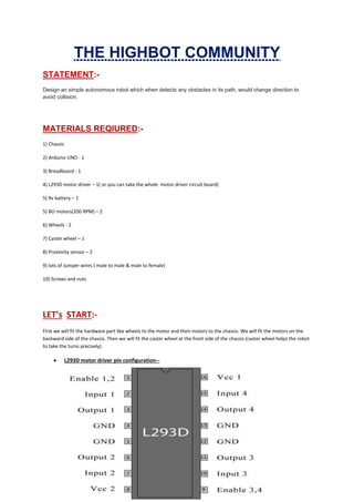
- 1. THE HIGHBOT COMMUNITY STATEMENT:- Design an simple autonomous robot which when detects any obstacles in its path, would change direction to avoid collision. MATERIALS REQIURED:- 1) Chassis 2) Arduino UNO - 1 3) Breadboard - 1 4) L293D motor driver – 1( or you can take the whole motor driver circuit board) 5) 9v battery – 1 5) BO motors(200 RPM) – 2 6) Wheels - 2 7) Caster wheel – 1 8) Proximity sensor – 2 9) lots of Jumper wires ( male to male & male to female) 10) Screws and nuts LET’s START:- First we will fit the hardware part like wheels to the motor and then motors to the chassis. We will fit the motors on the backward side of the chassis. Then we will fit the caster wheel at the front side of the chassis (caster wheel helps the robot to take the turns precisely). L293D motor driver pin configuration--
- 2. CONNECTIONS:- motor driver to arduino— 1) Short the 1, 9, 16 pin and connect it to the 5v power pin of arduino. 2) Short the 4, 5, 12, 13 pin and connect it to the ground pin of arduino. 3) Connect pin 2 to the digital pin 8 of arduino. 4) Connect pin 7 to the digital pin 9 of arduino. 5) Connect pin 10 to the digital pin 10 of arduino. 6) Connect pin 15 to the digital pin 11 of arduino. 7) Connect pin 8 to the Vin power pin of arduino.
- 3. BO motors to motor driver— As we know one motor has 2 wires ie; positive and negative. We are using two motors so total 4 wires we have. Motor 1 : Connect wire 1 to pin 3 and wire 2 to pin 6 of motor driver. Motor 2 : Connect wire 1 to pin 11 and wire 2 to pin 14 of motor driver. proximity sensor to arduino— Proximity sensor has total no. of 3 pins in it. First one is Vout second is GND(ground) and the third is Vcc. As we have two proximity sensor so, 1) Short two GND pins of the two sensors and connect it to the GND pin of arduino. 2) Short two Vcc pins of the two sensors and connect it to the 5v power pin of arduino. 3) Connect Vout pin of first sensor to A0 pin of arduino. 4) Connect Vout pin of second sensor to A1 pin of arduino. 9V battery to arduino— Connect red (positive) wire to Vin power pin and black (negative) wire to GND pin of arduino.