2878-CC-002 COORDINATED SERVICES LAYOUT
•
0 gostou•264 visualizações

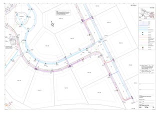
This document appears to be a map or layout plan showing the proposed electrical infrastructure for a development project. It includes labels for existing pipes, catch pits, telecom networks, underground and overhead electrical networks, as well as proposed electrical components like distribution pillars, street lighting poles, and electrical connections to individual plots of land. The layout also shows coordinates and labeling for road crossings, drainage structures, and references other drawings for additional details.

Recomendados
Mais conteúdo relacionado
Mais procurados
Mais procurados (20)
Semelhante a 2878-CC-002 COORDINATED SERVICES LAYOUT
Semelhante a 2878-CC-002 COORDINATED SERVICES LAYOUT (20)
Mais de Reza Bassawon
Mais de Reza Bassawon (11)
2878-CC-002 COORDINATED SERVICES LAYOUT
- 1. LEGEND Existing Pipe Dish Drain Catch Pit (Type 1) Catch Pit (Type 2) Telecom Network Plot Connection Underground realignment of existing overhead 22 kV CEB Network. 22 kV Cable. LV DP4 LV Feeder Cable from CEB Plantroom Sleeves Service Cable to each Plot Distribution Pillar Street Lighting Pole Refer to Road crossing schedule for Electrical Infrastructure LV DP3.1 LVDP2 LVDP3 LVDP3 LV DP3 LV DP3 LV DP3 LV DP3 LV DP3 LV DP3 LV DP3 LV DP3 LVDP4 LVDP4 LVDP4 LV DP4 LV DP4 LV DP4 LV DP4 LV DP4 LV DP4 LV DP4 LV DP4 LV DP4 LVDP4 LVDP4 LVDP4.1 LVDP4.1 LVDP4.1 LVDP4.1 LVDP3.1 LVDP3.1 LVDP3.1 LVDP3.1 LVDP3.1 Road 1 CP3-2 CP1-8a CP1-6 CP1-7 CP1-8 CP1-9 CP1-10 CP1-11 CP1-12 CP1-13 CP1-14 CP1-15 Outlet Structure 1 PLOT 36 PLOT 24 PLOT 26 PLOT 30 PLOT 32 PLOT 38 PLOT 29 PLOT 37 PLOT 31 PLOT 27 PLOT 25 PLOT 23 PLOT 33 PLOT 28 Air Valve in chamber Drain Valve in chamber Drain Valve in chamber Fire Hydrant 0.00 80.00 100.00 120.00 140.00 160.00 170.00 140.00 160.00 180.00 200.00 220.00 240.00 260.00 262.050 L3T No.2 L3T No.3 Telecom Distribution Cubicle L3T No.3 Road 3 N CEB Plantroom (PLR2) 1 x 500 kVA Transformer (Exact Position By Architect) Existing RMU 1.4 EXIST22kV MVCableFrom PLR2toPLR1 MVCableFrom PLR2toPLR1 ADP MV4 SDP MV16 DP 4 DP 3.1 DP 3 Draw Pit SC 8 (LV) E=996641.533 N=997434.294 E=996634.761 N=997428.485 E=996625.037 N=997433.339 E=996626.519 N=997422.011 E=996630.952 N=997413.340 E=996624.795 N=997405.161 E=996624.144 N=997394.752 E=996604.595 N=997390.529 E=996683.427 N=997376.431 E=996700.709 N=997381.043 E=996628.830 N=997383.036 Draw Pit SC 9 (LV) Draw Pit SC 10 (LV) Draw Pit SC 11 (LV) ADP LV TDP MV/LV (4.0 X 1.5m) TDP LV1To Supply Appartments SDP LV11 SDP LV10 SDP LV9 SDP LV8 SDP LV7 ADP MV7 ADP MV6 SDP MV17a Draw Pit SC 5 (LV) X X X X X X X X X X X X X X X X X X X X X X X X X X X X X X X X X X X X X X X X X X X X X X X X X X X X X X X X X X X X X X X X X X X X X X X X X X X X X X X X X X X X E=996648.497 N=997372.159E=996637.440 N=997375.386 Round About 1 RC 26 RC 27 RC 28 RC 29 RC 30 Air Valve in chamber SDP LV SDP LV Note : Refer to drawing 2878-CU-301 for position of sleeves entering draw pit in order to have a proper bending radius Road crossing Tee 110x110x110 2 x 5 Nos. 2 x 2 Nos. 177.484 Job No Drawing Status Discipline Scale at A1 Drawing No Rev Drawing Title Job Title Client Date By Chkd Appd A1 1 2 3 4 5 6 7 8 9 10 11 A B C D E F G H I J K L M N Do not scale Rev CC-002 C22878 1:750 FOR CONSTRUCTION Civil COORDINATED SERVICES LAYOUT Sheet 2 of 8 / /C1 15 03 13 Reza B. P.G P.G ISSUED FOR CONSTRUCTION N KEY PLAN KP 2 KEY PLAN 2 / /C2 22 04 13 Reza B. P.G P.G UPLIGHTER AT PLOT SERVICE HUB , PLOT 27 & 28 ENTRANCE MODIFIED , SERVICE HUB ADDED AND ROAD LENGTH EXTENDED