
Recomendados
Mais conteúdo relacionado
Mais procurados
Mais procurados (20)
Semelhante a CLIMO heat loss.pptx
Semelhante a CLIMO heat loss.pptx (20)
Último
Último (20)
CLIMO heat loss.pptx
- 1. THERMAL HEAT GAIN OR LOSS Presented by Ar.Chetan Tippa – Asst Prof - BGSSAP Source : https://learn.openenergymonitor.org/sustainable-energy/building-energy-model/readme
- 2. THERMAL HEAT GAIN OR LOSS Presented by Ar.Chetan Tippa – Asst Prof - BGSSAP Source : https://www.slideshare.net/RohitKumar79/3-principles-of-thermal-design
- 3. Presented by Ar.Chetan Tippa – Asst Prof - BGSSAP HEAT FLOW CONCEPT Heat flow is the flow of thermal energy from a body, at a high temperature, to another at a lower temperature. This transfer of thermal energy may occur under steady or unsteady state conditions. It happens by any of the flowing ways : • Conduction • Convection • Radiation Thermal Conductivity ( K value ) : It is a measure of heat flow ( flow of energy per unit time) through unit area of unit thickness of the material, when there is a unit temperature difference between the two sides. The lower the conductivity, the better insulator a material is. S.I unit – W/m deg C Resistivity : It is the reciprocal of Thermal conductivity . Unit m deg C / W. Conductance : Conductance is the heat flow through a unit area of the body ( ie the density of flow rate ) when the temperature difference between the two surfaces is 1 deg c. Unit of measurement is W/m2 deg c . Conductance = 1/R where R is resistance. Resistance of a body is the product of its thickness and resistivity of its material. R = b X 1/k = b/k where b is the thickness in meters. Cavities : Cavity Resistance ( Rc) for an empty cavity is the sum of an internal & external surface resistance ( 0.176 m2 deg C / W ).
- 4. Presented by Ar.Chetan Tippa – Asst Prof - BGSSAP Thermal Conductivity ( K value ) : It is a measure of heat flow ( flow of energy per unit time) through unit area of unit thickness of the material, when there is a unit temperature difference between the two sides. The lower the conductivity, the better insulator a material is. S.I unit – W/m deg C Resistivity : It is the reciprocal of Thermal conductivity . Unit m deg C / W. Conductance : Conductance is the heat flow through a unit area of the body ( ie the density of flow rate ) when the temperature difference between the two surfaces is 1 deg c. Unit of measurement is W/m2 deg c . Conductance = 1/R where R is resistance. Resistance of a body is the product of its thickness and resistivity of its material. R = b X 1/k = b/k where b is the thickness in meters. Cavities : Cavity Resistance ( Rc) for an empty cavity is the sum of an internal & external surface resistance ( 0.176 m2 deg C / W ). Specific heat : Specific heat of a substance is the amount of heat energy necessary to cause unit temperature increase of a unit mass of the substance. It is measured in J/kg degC. Thermal Capacity : Thermal capacity of a body is the product of its mass and specific heat of its material. It is measured as the amount of heat required to cause unit temperature increase of the body in units of J/degC
- 5. Presented by Ar.Chetan Tippa – Asst Prof - BGSSAP Multi layer body: The resistance of a multi layer body of different materials will be the sum of resistances of individual layers. • The conductance (C) can be found by finding its total resistance (R) and taking its reciprocal: • C=1/R • NOTE : Conductance are not additive but only the resistances. MULTI LAYER BODY Source : Manual of Tropical Housing and Building climatic design page no 72
- 6. Presented by Ar.Chetan Tippa – Asst Prof - BGSSAP The overall air-to-air resistance (Ra ) is the sum of the body's resistance and the surface resistances: Ra = 1/fi + Rb + 1/fo Where, 1/fi = internal surface resistance, Rb = resistance of the body, 1/fo = external surface resistance, all resistance values in m² degC/W OVERALL AIR TO AIR RESISTANCE
- 7. Presented by Ar.Chetan Tippa – Asst Prof - BGSSAP Surface Conductance : The resistance along with the body, the surface of a material offers a resistance as well, where a thin film of air separates the body from the surrounding air: Surface or thin film resistance. • Surface conductance is taken to be ‘f’, so surface resistance will be taken as 1/f. • It includes convective and radiant components of the heat exchange at surfaces. SURFACE CONDUCTANCE
- 8. Presented by Ar.Chetan Tippa – Asst Prof - BGSSAP Convection : In convection, heat is transferred by the bodily movement of a carrying medium, usually a gas or a liquid. The rate of heat transfer in convection depends on three factors: 1. Temperature difference (difference in temperature of the medium at the warmer and cooler points) . 2. The rate of movement of the carrying medium in terms of kg/s or m 3/s . 3. The specific heat of the carrying medium in J/kg degC or J/m 3 degC These quantities will be used in ventilation heat loss or cooling calculations.. CONVECTION
- 9. Presented by Ar.Chetan Tippa – Asst Prof - BGSSAP Radiation : In radiation heat transfer, the rate of heat flow depends on the temperatures of the emitting and receiving surfaces and on certain qualities of these surfaces: the emittance and absorbance. • Radiation received by a surface can be partly absorbed and partly reflected: the proportion of these two components is expressed by the coefficients absorbance (a) and reflectance (r). • The sum of these two coefficients is always one: a+r=1 Light coloured, smooth and shiny surfaces tend to have a higher reflectance. • For the perfect reflective theoretical white surface: r = 1, a = O. The perfect absorber, the theoretical 'black body', would have the coefficients: r = 0, a = 1. • It is measured in W/m2 RADIATION
- 10. Presented by Ar.Chetan Tippa – Asst Prof - BGSSAP U – Value : A measure of the heat transmission through a building part (such as a wall or window) or a given thickness of a material (such as insulation) with lower numbers indicating better insulating properties. • That is, how effective they are at preventing heat from transmitting between the inside and the outside of a building. • Reciprocal values of thermal resistance is the U-value . U=1/R .S.I unit – W/m2 deg C • This is the quantity most often used in building heat loss and heat gain problems , as its use greatly signifies the calculations. • The reciprocal of air ‐to ‐air resistance is the air to air transmittance or U ‐value. • A U value is a measure of heat loss in a building element such as a wall, floor or roof U - VALUE
- 11. Presented by Ar.Chetan Tippa – Asst Prof - BGSSAP EXERCISE U - VALUE
- 12. Presented by Ar.Chetan Tippa – Asst Prof - BGSSAP In this type of heat flow, the rate of heat flow remains constant with time considering both indoor & outdoor temperatures are constant. • The results can be taken as reliable if the fluctuations of temperature do bot exceed +- 3 deg C. Such situations may prevail in the winter of moderate climates when the temperature is heated and kept at a given temperature or in a warm-humid climate where the indoor temperature is kept constant by air conditioning. • Calculations based on steady state assumptions are useful to determine the maximum rate of heat loss or heat gain, also for the purpose of establishing the size & capacity of heating and cooling installations. • Prediction of thermal behaviour of the building is not the aim of this exercise – the mechanical controls will provide the necessary adjustments. • The designer only has to make sure that enough capacity is provided in heating or cooling to cope with the reasonably likely worst conditions. • Steady state calculation methods can usually be considered for preliminary studies. STEADY STATE HEAT FLOW CONCEPT
- 13. Presented by Ar.Chetan Tippa – Asst Prof - BGSSAP • In nature the variation of climatic conditions produces a non-steady state. Diurnal variations produce an approximately repetitive 24-hour cycle of increasing and decreasing temperatures. • The effect of this on a building is that in the hot period heat flows from the environment into the building, where some of it is stored, and at night during the cool period, the heat flow is reversed: from the building to the environment. • As the cycle is repetitive, it can be described as periodic heat flow PERIODIC HEAT FLOW CONCEPT Time lag & decrement factor Source : Manual of Tropical Housing and Building climatic design page no 84
- 14. Presented by Ar.Chetan Tippa – Asst Prof - BGSSAP • The diagram below shows the diurnal variations of external & internal temperatures in a periodically changing thermal regime. • In the morning, as the outdoor temperature increases, heat starts entering the outer surface of the wall. Each particle will absorb a certain amount of heat for every degree of rise in temperature depending on the specific heat of the wall material. • Heat to the next particle will only be transmitted after the temperature of the first particle has increased. Thus , the corresponding increase of the internal surface temperature will be delayed as shown by the broken line. • The outdoor temperature would have reached its peak and started decreasing before the inner surface temperature would have reached the same level. From this moment, the heat stored in the wall will be dissipated partly to the outside and only partly to the inside. • As the outdoor air cools, an increasing proportion of this stored heat flows outwards, and when the wall temperature falls below the indoor temperature the direction of heat flow is completely reversed. • The two quantities characterising this periodic change are the time-lag or phase shift (∮)and the decrement factor denoted by 𝜇. • The decrement factor is the ratio of the maximum outer and inner surface temperature amplitudes taken from the daily mean. TIME LAG & DECREMENT FACTOR
- 15. Presented by Ar.Chetan Tippa – Asst Prof - BGSSAP TIME LAG & DECREMENT FACTOR Time lag & decrement factor Source : Manual of Tropical Housing and Building climatic design page no 84
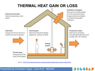
- 16. Presented by Ar.Chetan Tippa – Asst Prof - BGSSAP HEAT EXCHANGE OF BUILDINGS Heat Exchange of buildings Source : Manual of Tropical Housing and Building climatic design page no 75 • The Qi -Heat output from human bodies, lamps motors and appliances. • Qs -The effects of solar radiations on opaque surfaces(but through transparent surfaces window can be considered separately) can be included. • Qc -Conduction of wall may occur through the walls either inwards or outwards and is denoted by Qc • Qv - Heat exchange in either direction may take place with the movement of air i.e ventilation. • Qm - There may be introduction or removal of heat (heating or cooling) using some form of outside energy supply. The heat flow of such mechanical controls may be denoted as Qm • Qe - If evaporation takes place on the surface of the building (eg roof pool) or within the building (human sweat or water in fountain) and vapours are removed, it produces a cooling effect. The thermal balance, i.e. the existing thermal condition is maintained if: Qi + Qs ± Qc ± Qv ± Qm - Qe = 0 • The existing thermal condition maintained is cool if: Qi + Qs ± Qc ± Qv ± Qm - Qe = Negative • The existing thermal condition maintained is hot if: Qi + Qs ± Qc ± Qv ± Qm - Qe = Positive
- 17. Presented by Ar.Chetan Tippa – Asst Prof - BGSSAP CONDUCTION, CONVECTION Conduction heat flow rate through a wall of a given area can be described by the equation: • Qc = A x U x ∆T Where, Qc = conduction heat flow rate, in W, • A = surface area, in m², U = transmittance value in W/m² degC, • ∆T = temperature difference in degC Convection heat flow rate between the interior of a building and the open air depends on the rate of ventilation, i.e. air exchange. The rate of ventilation can be given in m³/s. The rate of ventilation heat flow is described by the equation: Qv = 1300 x V x ∆T Where, Qv = ventilation heat flow rate, in W, 1300 = volumetric specific heat of air, in J/m³ degC, V = ventilation rate in m³/s, ∆T = temperature difference in degC If the number of air changes per hour (N) is given the ventilation rate can be found as: V = (N x room volume) / 3600 where 3600 is the number of seconds in an hour.
- 18. Presented by Ar.Chetan Tippa – Asst Prof - BGSSAP RADIATION THROUGH WINDOWS The solar heat flow through windows is given by the equation: Qs = A x l x θ, Where, A= area of the window in m², l = radiation heat flow density in W/m², θ = solar gain factor of window glass
- 19. Presented by Ar.Chetan Tippa – Asst Prof - BGSSAP SOL –AIR TEMPERATURE • For building design purposes, it is useful to combine the heating effect of radiation incident on a building with the effect of warm air: sol‐air temperature concept. (Effect of Convection +radiation on building) • A temperature value is found which would create the same thermal effect as the incident radiation in question and this value is added to air temperature. • In cold climate (heat loss situation), a lesser surface conductance would help reducing heat loss. In warm climate (heat gain situation), a greater surface conductance would help in reducing solar over‐heating. • The reason being the incident radiation increases surface temperature far above the air temp. and some heat is dissipated to out door air immediately. Greater the surface conductance, more heat will be dissipated before it can be conducted away by wall. Sol – air temperature Source : Manual of Tropical Housing and Building climatic design page no 74
- 20. Presented by Ar.Chetan Tippa – Asst Prof - BGSSAP SOLAR GAIN FACTOR • To consider the combined effects of reflective surfaces and thermal insulation. • To reduce solar heat gain, a dark, highly absorptive surface with good insulation may be just as effective as a more reflective but less well‐insulated element. • Solar gain factor can be defined as the heat flow rate through the construction due to solar radiation expressed as a fraction of the incident solar radiation. • As this value can be related to the increase in the inner surface temperature, a performance requirement can be established on the basis of experience, in terms of this solar gain factor. • Value should not exceed 0.04 in warm humid climate and 0.03 in hot dry part of composite climate when ventilation is reduced. Solar gain factor Source : Manual of Tropical Housing and Building climatic design page no 74