
Recomendados
Recomendados
Mais conteúdo relacionado
Mais procurados
Mais procurados (20)
Semelhante a Coates Hire - Trench Shoring Solutions
Semelhante a Coates Hire - Trench Shoring Solutions (20)
Mais de Rafi Tchopourian
Mais de Rafi Tchopourian (19)
Último
Último (20)
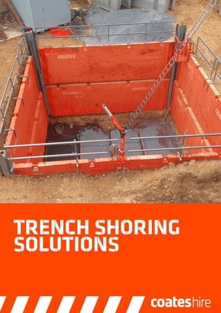
Coates Hire - Trench Shoring Solutions
- 2. 2 // TRENCH SHORING SOLUTIONS Contact us: 13 15 52 | TechnicalDesigns@coateshire.com.au At Coates Hire, we offer the highest quality equipment and we equip our customers with the best expertise in the industry. Our experts provide advice on evaluating the risks associated with equipment supply, performance and operation. Our Engineering Services Team offers comprehensive technical support and we can assist in the concept and design of all engineering solutions. All of which ensures that your site is always performing to its full potential. Our unique ability to provide total equipment solutions helps you drive both time and cost efficiencies. We have the expertise to ensure you have everything you need, anytime you need it. So no matter how big or small your project is, you can count on Coates Hire to help make it happen. • Commitment to Safety: We are passionately commited to safety, helping deliver your project on time whilst ensuring you’re meeting duty of care obligations. • 130 Years’ Experience: We have a track record that spans every market sector, helping to deliver successful projects across a wide range of industries • Project Support: Over 600 branch managers, field sales and product specialists are committed to providing complete solutions to your specific project needs. • Industry Leading Customer Service: At Coates Hire we take customer service seriously and ensure we are continually improving your experience. • Engineering and Technical: Our dedicated team of experts can provide technical solution, design, certification and installation services for temporary works requirements. • R&D Capabilities: Our research, development & innovation arm constantly strives to find new and better solutions, systems and equipment for our customers. OUR EXPERTISE:
- 3. // 3 TRENCH SHORING SOLUTIONS Aluminium Vertishore Ideal for trench excavations in cohesive soils (clay), Vertishores are a rapidly deployed solution used to stabilise the walls of an excavated trench to allow safe access. Vertishores are light enough to be installed by manual handling and can be used for a range of different trench depths & widths. Perfect for confined sites with limited access to heavy plant and machinery. ALUMINIUM VERTISHORE SPECIFICATIONS V450- 900 V450- 1400 V1050- 900 V1050- 1400 V1500- 900 V1500- 1400 V2100- 900 V2100- 1400 V2400- 900 V2400- 1400 Length of rail (mm) 450 450 1070 1070 1500 1500 2130 2130 2440 2440 Width of rail (mm) 209 204 204 204 204 204 204 204 204 204 No. cylinders - 1 1 2 2 2 2 2 2 2 2 Min. trench width (mm) 560 865 560 865 560 865 560 865 560 865 Max. trench width (mm) 1740 2300 1740 2300 1740 2300 1740 2300 1740 2300 Stroke (mm) 340 535 340 535 340 535 340 535 340 535 Max. trench depth (mm) - - 2435 2435 2460 2460 3015 3015 3015 3015 Weight per unit (kg) 11 13 23 28 28 32 32 37 43 53
- 4. 4 // TRENCH SHORING SOLUTIONS Contact us: 13 15 52 | TechnicalDesigns@coateshire.com.au Aluminium Shoring Shields provide an extremely light-weight solution for shielding a work zone inside an excavated trench. Lowered into position after excavation has been performed, our range of Aluminium Shoring Shields can be easily lifted and moved using small excavators. This makes them rapid and easy to install, extract, or to move along a trench excavation as construction progresses. A range of panel & strut sizes are available to suit almost any small to medium size trench excavation. STANDARD ALUMINIUM SHORING SHIELDS SPECIFICATIONS Model (L x H) Length Height Pipe Clearance Length Clear Working Width Under Strut Clearance Capacity Box Weight (min internal) L H Lc Bp / Bc hc Stat. Strut Hyd. Strut (kg) Min Max Es Eh (m) (m) (m) (m) (m) (m) (kPa) (kPa) 1.8m x 1.8m 1.83 1.83 1.45 0.40/0.63 2.08/2.31 0.56 53 110 378 2.4m x 1.8m 2.44 1.83 1.90 0.40/0.63 2.08/2.31 0.56 53 67 446 1.8m x 2.4m 1.83 2.44 1.45 0.40/0.63 2.08/2.31 0.56 53 81 426 2.4m x 2.4m 2.44 2.44 1.90 0.40/0.63 2.08/2.31 0.56 53 67 505 L B bp hc Lc H tpl bc Aluminium Shield Dimension Diagram Aluminium Shoring Shield Aluminium Shoring Shields Dimension Diagram
- 5. // 5 TRENCH SHORING SOLUTIONS Aluminium Shoring Shield SMOOTH WALL ALUMINIUM SHORING SHIELD SPECIFICATIONS Model (L x H) Length Height Pipe Clearance Length Clear Working Width Under Strut Clearance Capacity Box Weight (min internal) L H Lc Bp / Bc hc E (kg)Min Max (m) (m) (m) (m) (m) (m) (kPa) 1.8m x 1.8m 1.83 1.83 1.30 0.40/0.63 2.08/2.31 0.81 105 430 2.4m x 1.8m 2.44 1.83 1.90 0.40/0.63 2.08/2.31 0.81 79 543 1.5m x 2.4m 1.52 2.44 0.99 0.40/0.63 2.08/2.31 1.19 90 454 1.8m x 2.4m 1.83 2.44 1.30 0.40/0.63 2.08/2.31 1.19 80 512 2.4m x 2.4m 2.44 2.44 1.90 0.40/0.63 2.08/2.31 1.19 60 629 3.6m x 2.4m 3.66 2.44 3.12 0.35/0.63 2.03/2.31 1.19 29 859 L B bp hc Lc H tpl bc Aluminium Shield Dimension DiagramAluminium Shoring Shield Dimension Diagram
- 6. 6 // TRENCH SHORING SOLUTIONS Contact us: 13 15 52 | TechnicalDesigns@coateshire.com.au SUPER ALUMINIUM SHIELD – HIGH CLEARANCE CONFIGURATION Model Length Total Pipe Clearence Length Height Clear Working Width Understrut Clearance Capacity Panel Thickness Box Weight (min internal) L Lc H bc hc E tpl Min Max (m) (m) (m) (m) (m) (m) (kPa) (mm) (kg) 4.5m Lower Only 4.5 4.0 2.3 1.48 4.48 2.2 42 150 3292 4.5m Lower + Upper 4.5 4.0 4.0 1.48 4.48 2.2 42 150 4736 7.3m Lower Only 7.3 6.8 2.3 1.48 4.48 2.2 36 180 4268 7.3m Lower + Upper 7.3 6.8 4.0 1.48 4.48 2.2 36 180 6612 Shield Dimension Diagram (High Clearance configration) L B bc tpl H hc Lc Super Aluminium Shoring Shield The ultimate aluminium shoring shield. The Super Aluminium Shoring Shield combines the light-weight advantages of aluminium construction, with a design engineered for strength and size. This produces a shoring shield that allows you to take your excavation longer, wider & deeper, while still using standard size plant and machinery typically available on a construction site. The Super Aluminium Shoring Shield is ideal for large trenching and pit applications where productivity is critical. SUPER ALUMINIUM SHIELD – STANDARD CONFIGURATION (REFER OVER LEAF FOR IMAGE) Model Length Total Pipe Clearance Length Height Clear Working Width Understrut Clearance Capacity Panel Thickness Box Weight (min internal) L Lc H bc hc E tpl Min Max (m) (m) (m) (m) (m) (m) (kPa) (mm) (kg) 4.5m Lower 4.5 4.0 2.3 1.0 4.0 1.4 42 150 2352 4.5m Upper 4.5 4.0 1.7 1.0 4.0 - 42 150 2064 7.3m Lower 7.3 6.8 2.3 1.0 4.0 1.4 36 180 3400 7.3m Upper 7.3 6.8 1.7 1.0 4.0 - 36 180 2892 Shield Dimension Diagram (Standard Configuration) HH L B hc bc tpl Lc Shield Dimension Diagram (Standard Configuration) Shield Dimension Diagram (High Clearance Configuration)
- 7. // 7 TRENCH SHORING SOLUTIONS Series 100 Light Shield SERIES 100 LIGHT SHIELD Model Length Total Pipe Clearence Length Height Clear Working Width Understrut Clearance Capacity Panel Thickness Box Weight (min internal) L Lc H bc hc E tpl Min Max (m) (m) (m) (m) (m) (m) (kPa) (mm) (kg) LOWER SHIELD 2.0m x 1.6m 2.0 1.63 1.6 0.6 4.0 1.0 48 60 670 2.0m x 2.0m 2.0 1.63 2.0 0.6 4.0 1.2 48 60 790 2.0m x 2.4m 2.0 1.63 2.4 0.6 4.0 1.2 48 60 900 2.5m x1.6m 2.5 2.13 1.6 0.6 4.0 1.0 38 60 760 2.5m x 2.0m 2.5 2.13 2.0 0.6 4.0 1.2 38 60 890 2.5m x 2.4m 2.5 2.13 2.4 0.6 4.0 1.2 38 60 1020 3.0m x 1.6m 3.0 2.63 1.6 0.6 4.0 1.0 32 60 850 3.0m x 2.0m 3.0 2.63 2.0 0.6 4.0 1.2 32 60 990 3.0m x 2.4m 3.0 2.63 2.4 0.6 4.0 1.2 32 60 1140 UPPER SHIELD 2.0m x 1.0m 2.0 1.63 1.0 0.6 4.0 - 48 60 500 2.5m x 1.0m 2.5 2.13 1.0 0.6 4.0 - 38 60 560 3.0m x 1.0m 3.0 2.63 1.0 0.6 4.0 - 32 60 620 Series 100 Shield Dimension Diagram L H bc H H hc tpl Lc The Series 100 Light Shield is ideal for small to medium pit & trenching excavations where there is limited access to heavy plant & machinery on site. This efficiently designed shield achieves an excellent pressure capacity rating, while still keeping the assembled shield weight to a minimum. In addition to this, its steel construction and simple design produces an extremely robust and versatile shoring solution. Series 100 Shield Dimension Diagram
- 8. 8 // TRENCH SHORING SOLUTIONS Contact us: 13 15 52 | TechnicalDesigns@coateshire.com.au Manhole Shoring Box SERIES 600 MANHOLE SHORING BOX Model Length Total Pipe Clearence Length Height Clear Working Width Understrut Clearance Capacity Panel Thickness Box Weight (min internal) L Lc H bc hc E tpl Min Max (m) (m) (m) (m) (m) (m) (kPa) (mm) (kg) 2.5m Lower 2.5 2.1 2.5 1.5 6.8 1.53 50.1 107.0 2356 2.5m Upper 2.5 2.1 1.5 1.5 6.8 - 50.1 107.0 1623 3.0m Lower 3.0 2.6 2.5 1.5 6.8 1.53 41.8 107.0 2737 3.0m Upper 3.0 2.6 1.5 1.5 6.8 - 41.8 107.0 1987 M41 MANHOLE SHORING BOX (WA & NT ONLY) Model Length Total Pipe Clearence Length Height Clear Working Width Understrut Clearance Capacity Panel Thickness Box Weight (min internal) L Lc H bc hc E tpl Min Max (m) (m) (m) (m) (m) (m) (kPa) (mm) (kg) 2.6m Lower 2.6 2.2 2.5 1.6 5.0 1.50 41.0 108.0 3140 2.6m Upper 2.6 2.2 1.5 1.6 5.0 - 41.0 108.0 1970 3.0m Lower 3.0 2.6 2.5 1.6 5.0 1.50 41.0 108.0 3530 3.0m Upper 3.0 2.6 1.5 1.6 5.0 - 41.0 108.0 2170 Manhole boxes are ideal for construction of manholes and chambers along a linear excavation such as a pipe installation. Our range of manhole boxes are designed to be flexible, robust, and suit most typical manhole construction sizes. Manhole Box Dimension Diagram LB bc tpl Lc HH hc Manhole Box Dimension Diagram
- 9. // 9 TRENCH SHORING SOLUTIONS Series 600 Standard Box SERIES 600 STANDARD SHORING BOX– STANDARD CONFIGURATION Model Length Total Pipe Clearence Length Height Clear Working Width Understrut Clearance Capacity Panel Thickness Box Weight (min internal) L Lc H bc hc E tpl Min Max (m) (m) (m) (m) (m) (m) (kPa) (mm) (kg) 3.0m Lower 3.0 2.6 2.4 0.7 6.0 1.53 53.5 107.0 2022 3.0m Upper 3.0 2.6 1.4 0.7 6.0 - 53.5 107.0 1236 3.5m Lower 3.5 3.1 2.4 0.7 6.0 1.53 48.9 107.0 2150 3.5m Upper 3.5 3.1 1.4 0.7 6.0 - 48.9 107.0 1350 4.0m Lower 4.0 3.6 2.4 0.7 6.0 1.53 40.1 107.0 2572 4.0m Upper 4.0 3.6 1.4 0.7 6.0 - 40.1 107.0 1586 4.0m HD Lower 4.0 3.6 2.5 0.7 6.0 1.53 70.0 127.0 3012 4.0m HD Upper 4.0 3.6 1.4 0.7 6.0 - 70.0 127.0 1806 5.0m Lower 5.0 4.6 2.4 0.7 6.0 1.53 38.0 127.0 3290 5.0m Upper 5.0 4.6 1.4 0.7 6.0 - 38.0 127.0 2136 6.0m Lower 6.0 5.6 2.4 0.7 6.0 1.53 27.6 127.0 4172 6.0m Upper 6.0 5.6 1.4 0.7 6.0 - 27.6 127.0 3086 6.0m HD Lower 6.0 5.6 2.4 0.7 6.0 1.53 40.0 130.0 4432 6.0m HD Upper 6.0 5.6 1.4 0.7 6.0 - 40.0 130.0 2786 The Series 600 Shoring Box range provides a shoring solution for almost any medium to large sized pit or trench excavation. With an extensive range of high capacity panels and struts, the Series 600 Box can be assembled to a vast array of different sizes to suit your needs. This system is designed to be high capacity and extremely robust enabling it to stand up to the most challenging of site conditions. It can be installed as a traditional shoring shield, or using the “dig & push” method which is ideal for installation in weak or unstable ground. Series 600 Standard Box Dimention Diagram-Standard Configration bc HH Lc tpl L B hc Series 600 Standard Box Dimension Diagram (Standard Configuration)
- 10. 10 //TRENCH SHORING SOLUTIONS Contact us: 13 15 52 | TechnicalDesigns@coateshire.com.au Series 600 Standard Box SERIES 600 STANDARD SHORING BOX – HIGH CLEARANCE CONFIGURATION (LOWER + UPPER) Model Length Total Pipe Clearence Length Height Clear Working Width Understrut Clearance Capacity Panel Thickness Box Weight (min internal) L Lc H bc hc E tpl Min Max (m) (m) (m) (m) (m) (m) (kPa) (mm) (kg) 3.0m 3.0 2.6 3.7 1.03 6.33 2.3 49.9 107.0 4944 3.5m 3.5 3.1 3.7 1.03 6.33 2.3 42.8 107.0 5396 4.0m 4.0 3.6 3.7 1.03 6.33 2.3 37.4 107.0 5844 5.0m 5.0 4.6 3.7 1.03 6.33 2.3 29.9 127.0 7112 6.0m 6.0 5.6 3.7 1.03 6.33 2.3 24.9 127.0 8944 To further increase the versatility of the Series 600 Box, a High Clearance option is available. This provides all of the features & benefits of the Standard Configuration, with a significantly increased clearance under the lowest strut. Ideal for installation of large pipes & culverts. Series 600 Standard Box Dimension Diagram-High Clearance Configration L B bc tpl hc H Lc Series 600 Standard Box Dimension Diagram (High Clearance Configuration)
- 11. // 11 TRENCH SHORING SOLUTIONS M41 Standard Box (WA & NT Only) M41 STANDARD SHORING BOX – STANDARD CONFIGURATION Model Length Total Pipe Clearence Length Height Clear Working Width Understrut Clearance Capacity Panel Thickness Box Weight (min internal) L Lc H bc hc E tpl Min Max (m) (m) (m) (m) (m) (m) (kPa) (mm) (kg) 3.6m Lower 3.6 3.34 2.5 0.6 4.0 1.50 41.0 108.0 2792 3.6m Upper 3.6 3.34 1.5 0.6 4.0 - 41.0 108.0 1796 4.0m Lower 4.0 3.74 2.5 0.6 4.0 1.50 41.0 108.0 3142 4.0m Upper 4.0 3.74 1.5 0.6 4.0 - 41.0 108.0 2046 M41 STANDARD SHORING BOX – HIGH CLEARANCE CONFIGURATION (LOWER + UPPER) Model Length Total Pipe Clearence Length Height Clear Working Width Understrut Clearance Capacity Panel Thickness Box Weight (min internal) L Lc H bc hc E tpl Min Max (m) (m) (m) (m) (m) (m) (kPa) (mm) (kg) 3.6m 3.6 3.34 4.0 1.10 4.75 2.6 41.0 108.0 6060 4.0m 4.0 3.74 4.0 1.10 4.75 2.6 41.0 108.0 6660 The M41 Standard Box range is designed to be high capacity and extremely robust, enabling it to stand up to the most challenging of site conditions. It can be installed as a traditional shoring shield, or using the “dig & push” method which is ideal for installation in weak or unstable ground. To further increase the versatility of the M41 Standard Box , a High Clearance option is available. This provides all of the features & benefits of the Standard Configuration, with a significantly increased clearance under the lowest strut. Ideal for installation of large pipes & culverts. M41 Standard Box Dimension Diagram-Standard Configuration H H L B bc tpl hc Lc M41 Standard Box Dimension Diagram-High Clearance Configuration LB bc H hc Lc tpl M41 Standard Box Dimension Diagram (Standard Configuration) M41 Standard Box Dimension Diagram (High Clearance Configuration)
- 12. 12 //TRENCH SHORING SOLUTIONS Contact us: 13 15 52 | TechnicalDesigns@coateshire.com.au Rolling Strut Box SERIES 600 ROLLING STRUT BOX Model Length Total Pipe Clearence Length Height Clear Working Width Understrut Clearance Panel Capacity* Panel Thickness Box Weight (min internal) L Lc H bc hc E tpl Min Max (m) (m) (m) (m) (m) (m) (kPa) (mm) (kg) 3.0m (SSR Strut) 3.0 2.3 3.7 2.69 > 6.0 1.2 - 2.5 53.5 107.0 5760 3.0m (DSR Strut) 1.9 - 1.5 6480 3.5m (SSR Strut) 3.5 2.8 1.2 - 2.5 48.9 107.0 6212 3.5m (DSR Strut) 1.9 - 1.5 6932 4.0m (SSR Strut) 4.0 3.3 1.2 - 2.5 40.1 107.0 6660 4.0m (DSR Strut) 1.9 - 1.5 7380 4.0m HD (SSR Strut) 4.0 3.3 1.2 - 2.5 70.0 127.0 7320 4.0m HD (DSR Strut) 1.9 - 1.5 8040 5.0m (SSR Strut) 5.0 4.3 1.2 - 2.5 38.0 127.0 7928 5.0m (DSR Strut) 1.9 - 1.5 8648 6.0m (SSR Strut) 6.0 5.3 1.2 - 2.5 27.6 127.0 9760 6.0m (DSR Strut) 1.9 - 1.5 10480 6.0m HD (SSR Strut) 6.0 5.3 1.2 - 2.5 40.0 130.0 9720 6.0m HD (DSR Strut) 1.9 - 1.5 10440 Rolling Strut Boxes are ideal for applications where extremely wide excavation dimensions are required. The bolt-together strut assembly means that there is no fixed limit to strut length, subject to a free-of-charge design review by Coates Hire’s team of in-house engineers. Added to this the flexibility of the rolling strut allows variable strut positioning to enable the user to avoid obstructions within the excava-tion zone during excavation & construction. *Capacity subject to confirmation by a suitably qualified engineer. “SSR” = Single Slide Rail (ref. following section) “DSR” = Double Slide Rail (ref. following section) Series 600 Rolling Strut Box-Std. Configuration L B bc tpl hc H Lc Series 600 Rolling Strut Box (Standard Configuration)
- 13. // 13 TRENCH SHORING SOLUTIONS Rolling Strut Box 7.4M LARGE ROLLING STRUT BOX Model Length Total Pipe Clearence Length Height Clear Working Width Understrut Clearance Panel Capacity Panel Thickness Box Weight (min internal) L Lc H bc hc E tpl Min Max (m) (m) (m) (m) (m) (m) (kPa) (mm) (kg) Lower 7.4 6.4 2.4 1.35 > 6.0 1.56 57.0 170.0 8840 Upper 1.6 1.35 - 57.0 170.0 6940 High Clear 4.0 1.85 2.50 53.0 170.0 17220 7.4 Large Rolling Strut Box-High Clearance Configuration L B bc tpl H hc Lc 7.4 Large Rolling Strut Box (High Clearence Configuration)
- 14. 14 //TRENCH SHORING SOLUTIONS Contact us: 13 15 52 | TechnicalDesigns@coateshire.com.au Slide Rail Shoring—Trench Configuration SINGLE SLIDE RAIL* Panel Type (Length) Module Length Pipe Clearence Length Height Clear Working Width Understrut Clearance Panel Capacity Panel Thickness Ls Lc H bc hc E tpl Min Max (m) (m) (m) (m) (m) (m) (kPa) (mm) 2.0m 2.27 1.84 2.4 - 3.8 1.25 >6.0^ 0.99 - 2.31 158.0 107.0 3.0m 3.27 2.84 148.0 130.0 4.0m 4.27 3.84 66.0 107.0 4.0m HD 4.27 3.84 82.0 130.0 6.0m 6.27 5.84 60.0 150.0 7.4m 7.67 7.20 57.0 180.0 DOUBLE SLIDE RAIL* Panel Type (Length) Module Length Pipe Clearence Length Height Clear Working Width Understrut Clearance Panel Capacity Panel Thickness Ls Lc H bc hc E tpl Min Max (m) (m) (m) (m) (m) (m) (kPa) (mm) 2.0m 2.27 1.84 2.4 - 9.0 1.25 >6.0^ 1.42—3.42 158.0 107.0 3.0m 3.27 2.84 148.0 130.0 4.0m 4.27 3.84 66.0 107.0 4.0m HD 4.27 3.84 82.0 130.0 6.0m 6.27 5.84 60.0 150.0 7.4m 7.67 7.20 57.0 180.0 Slide Rail is the ultimate in steel shoring solutions. It is the most robust & flexible shoring method for large excavations on the market, and allows you to take your excavations longer, wider & deeper than with any other product. It offers unrivalled pressure rating, allowing excavation depths of up to 9.0m in most conditions, and offers the largest under-strut clearance of any product on the market. *All applications of Slide Rail should be assessed by a suitably qualified engineer. ^Additional strut lengths are achievable depending on the application. Slide Rail Dimension Diagram-Trench Configuration L B tpl bc H Lc hc Slide Rail Dimension Diagram-Trench Configuration
- 15. // 15 TRENCH SHORING SOLUTIONS Slide Rail Shoring—Pit Shoring Configuration* SLIDE RAIL SHORING—PIT SHORING CONFIGURATION* Pit Size (Panel Length x Panel Length) Module Length Internal Clearance Length Module Width Internal Clearance Width Height (Single Slide Rail Configuration) Height (Single Slide Rail Configuration) Minimum Panel Capacity Ls Lc B bc H H E (m) (m) (m) (m) Min Max Min Max (kPa) (m) (m) (m) (m) 2.0m x 2.0m 2.5 2.2 2.5 2.2 2.4 3.8 2.4 9.0 REFER SLIDE RAIL SHORING TRENCH CONFIG. SECTION 2.0m x 3.0m 2.5 2.2 3.5 3.2 2.0m x 4.0m 2.5 2.2 4.5 4.2 2.0m x 6.0m 2.5 2.2 6.5 6.2 2.0m x 7.4m 2.5 2.2 8.3 7.3 3.0m x 3.0m 3.5 3.2 3.5 3.2 3.0m x 4.0m 3.5 3.2 4.5 4.2 3.0m x 6.0m 3.5 3.2 6.5 6.2 3.0m x 7.4m 3.5 3.2 8.3 7.3 4.0m x 4.0m 4.5 4.2 4.5 4.2 4.0m x 6.0m 4.5 4.2 6.5 6.2 4.0m x 7.4m 4.5 4.2 8.3 7.3 6.0m x 6.0m 6.5 6.2 6.5 6.2 6.0m x 7.4m 6.5 6.2 8.3 7.3 7.4m x 7.4m 8.3 7.3 8.3 7.3 To add to Slide Rail’s extensive range of capabilities, the addition of 90 degree corner posts allows for fully enclosed pit excavations to be achieved. Using the corner posts with the extensive range of panels, and their extremely high pressure rating, almost any size pit excava-tion can be shored. Slide Rail Diamension Diagram-Pit Shoring Configration L B H bc Lc *All applications of Slide Rail should be assessed by a suitably qualified engineer. Slide Rail Dimension Diagram-Pit Shoring Configuration
- 16. 16 //TRENCH SHORING SOLUTIONS Contact us: 13 15 52 | TechnicalDesigns@coateshire.com.au Safety • Safety is embodied in everything we do and we work closely with our customers to create the safest working environment possible • Our complete range of excavation safety products are NATA tested & accredited and compliant to Australian Standards EDGE PROTECTION Coates Hire edge protection hand rails are compatible with our entire fleet of aluminium and steel shoring panels. The adjustable hand rail unit provides a flexible and rapid solution for edge protection around excavations of any size. The hand rail units are light- weight and in full compliance with AS1657. RESCUE SYSTEMS The Coates Hire davit rescue system provides a fast and easy solution to meeting safety requirements associated with working in deep excavations. The simple design clamps onto the side of any Coates Hire shoring panel, making installation fast & user friendly. All davit systems are supplied as a comprehensive kit in a secure, lockable storage case. EDGE PROTECTION Model Length Height Weight (m) (m) (kg) 3m 3.0 1.0 19.8 4m 4.0 1.0 21.6
- 17. // 17 TRENCH SHORING SOLUTIONS Safety LADDER ACCESS SYSTEMS & PLATFORMS Means of access and egress into deep excavations can often pose an issue on sites where space is at a premium. To provide a simple and cost effective solution to this challenge, Coates Hire carries a range of temporary access systems which are fast and easy to install, and do not require a specialist contractor.
- 18. 18 //TRENCH SHORING SOLUTIONS Contact us: 13 15 52 | TechnicalDesigns@coateshire.com.au Engineering & Technical Support EMS 648129FS 648130 OHS 648128 OHS 648127 *Environmental certification (ISO4001) achieved at Head Office and an expanding number of branches. At Coates Hire, we have been providing a wide range of specialist equipment and services for over 130 years. We pride ourselves in providing much more than just our product range. Our aim is to meet our customers’ safety, compliance, productivity, environmental and cost management expectations. Our equipment offering is supported by an in-house Temporary Works Department of highly trained and fully qualified Certifying Engineers, Design Engineers & Drafters, Regional Sales Engineers and Product Specialists. This allows us to provide a level of Engineering & Technical support for your project like no other supplier in the market. KEY CAPABILITIES • Fully qualified National Engineering department with extensive experience in temporary works design & installation • Professionally presented design solutions & drawings using the latest CAD software • Tender support packages for estimators and planning functions including budget costing • Support for site teams to develop best solutions and cost effective design options to keep within timescales and budget expectations • Engineering design sign off and installation sign off provided with equipment hire (CPEng, NER, RPEQ) • Risk Assessments both generic and project-specific • Safety in design • Develop safe and sustainable solutions • Training and coaching of site staff in all products via a range of tool box talks and ongoing support to help keep projects on track and provide safest possible working environment • ISO Accredited for Quality, Environmental, & OHS Management
- 19. Access Air & Air Accessories Compaction Concrete & Masonry Earthmoving Floor and Cleaning Equipment Generators & Power Distribution Industrial tools & Equipment Ladders & Scaffold Landscaping Lift & Shift Lighting Materials Handling Portable Buildings & Toilets Propping Pumps & Fluid Management Shoring Tools & Equipment Traffic Management Training (RTO) Trucks, Vehicles & Trailers Welding COATES HIRE’S AVAILABLE PRODUCT RANGE: At Coates Hire, you’ll find an unmatched range of equipment, available and ready to hire. We stock Australia’s largest fleet from general hire gear and specialist products, to total site solutions. With the largest branch network in Australia, you are backed by one of the country’s largest delivery networks.
- 20. WhileCoatesHiremakeseveryefforttosupplytheequipment described and pictured in this brochure, all equipment offered is subject to availability. Should Coates Hire through whatever circumstances need to offer an alternative make or model, customers can be assured that this will be of the same quality as the item shown or displayed in this brochure. All information about equipment in this brochure is to the best of our knowledge correct, but we would urge customers to check all details at the time of hire or enquiry. Coates Hire reserves the right to change information without prior notice. ISSUE1.0